Disclosure to Promote the Right To Information
Whereas the Parliament of India has set out to provide a practical regime of right to
information for citizens to secure access to information under the control of public authorities,
in order to promote transparency and accountability in the working of every public authority,
and whereas the attached publication of the Bureau of Indian Standards is of particular interest
to the public, particularly disadvantaged communities and those engaged in the pursuit of
education and knowledge, the attached public safety standard is made available to promote the
timely dissemination of this information in an accurate manner to the public.
इंटरनेट
मानक
“!ान $ एक न' भारत का +नम-ण”
Satyanarayan Gangaram Pitroda
“Invent a New India Using Knowledge”
“प0रा1 को छोड न' 5 तरफ”
Jawaharlal Nehru
“Step Out From the Old to the New”
“जान1
का
अ+धकार
,
जी1
का
अ+धकार”
Mazdoor Kisan Shakti Sangathan
“The Right to Information, The Right to Live”
“!ान एक ऐसा खजाना > जो कभी च0राया नहB जा सकता ह
ै
”
Bhartṛhari—Nītiśatakam
“Knowledge is such a treasure which cannot be stolen”
“Invent a New India Using Knowledge”
ह
ै
”
ह
”
ह
IS 7401 (1987): Paraffin wax for explosive and pyrotechnic
industry [CHD 26: Explosives and Pyrotechnics]
IS : 7401 - 1987
Indian Standard
SPECIFICATION FOR
PARAFFIN WAX FOR EXPLOSIVE AND
PYROTECHNIC INDUSTRY
( First Revision )
UDC 665.637.7 : 662.l/.4© Copyright 1988
B U R E A U O F I N D I A N S T A N D A R D S
MANAK BHAVAN, 9 BAHADUR SHAH ZAFAR MARG NEW DELHI 110002
AMENDMENT NO. 1 FEBRUARY 2001 TO
IS 7401 : 1987 SPECIFICATION FOR PARAFFIN WAX FOR EXPLOSIVES AND PYROTECHNIC INDUSTRY
(First Revision)
( Page 1, clause 3.2 ) — Substitute the following for the existing clause:
'3.2 The material shall also comply with the requirements laid down in Table 1 when tested according to the methods prescribed in P series of IS 1448*, IS 5741† and Appendix A to this standard. Reference to the relevant clauses of Appendix A, relevant P series of IS 1448* and IS 5741 : 1970† is given in columns 5, 6 and 7 of the table.'
( Page 1, footnote ) — Insert the following footnote at the end: '†Methods for determination of pH.'
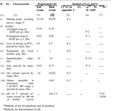
( Page 1, Table 1 ) — Substitute table given on page 2 for the existing table:
Amend No. 1 to IS 7401 : 1987
Table 1 Requirements for Paraffin Wax for Explosive and Pyrotechnic Industry
Sl No. Characteristic
(1) (2) i) Melting point (cooling
curve), range,°C ii) Acidity:
a) Organic (mg of KOH per g), Max b) Inorganic (mg of
KOH per g ), Max iii) Loss on drying at 90°C,
percent by mass, Max iv) Penetration (by Vicat
needle), mm, Max v) Saponification value,
Max
vi) Ask, percent by mass, Max
vii) Oil content, percent by maaa, Max
viii) Matter insoluble in petroleum ether ( 60-90°C BP range ), percent by mass, Max ix) pH of 5 percent of water extract in 100 ml of boiled antral Requirement for Soft Hard Grade Grade (3) 52-56 0.10 0.02 0.5 3 1.0 0.03 1.0
–
(4)
60-64 0.10 0.02 0.5 1 1.0 0.33 0.025 0.05 6.0-7.5Method of Test, Ref to Cl NO In (P) of IS No. Appendix A IS 1448* (5) A-2 –
—
A-3 A-4—
—
A-5 A-7—
(6) – P:2 P : 2—
—
P:55 P : 4–
–
–
(7)–
–
—
—
—
—
—
—
–
5741: 1970† *Methods of test for petroleum and its products.†Methods for determination of pH.
Amend No. 1 to IS 7401 : 1987
( Page 9, clause A-6.6.1 ) — Insert the following new clause A-7 at the end:
'A-7 DETERMINATION OF MATTER INSOLUBLE IN PETROLEUM ETHER
A-7.1 Outline of the Method — The sample is dissolved in petroleum ether (60-90°C BP range). The solution is then filtered and the residue is dried and weighed to constant mass.
A-7.2 Procedure — Weigh accurately about 5 g of the sample and digest with 100 ml of petroleum ether (60-90°C BP range) in a covered vessel on a steam bath until all the wax is dissolved. Filter through a tared, dried gooch crucible and wash it several times with warm petroleum ether to remove all the ether solubles. Dry the gooch crucible with residue and weigh to constant mass.
A-7.3 Calculation
Matter insoluble in petroleum ether, percent by mass = where
m = mass, in g, of matter insoluble in petroleum ether, and
M = mass, in g, of the material taken for the test.
( CHD 26 )
Reprography Unit, BIS, New Delhi, India
IS : 7401 - 1987
Indian Standard
SPECIFICATION FOR
PARAFFIN WAX FOR EXPLOSIVE AND
PYROTECHNIC INDUSTRY
( First Revision )
0. F O R E W O R D
0.1 This Indian Standard (First Revision) was adopted by the Bureau of Indian Standards on 30 October 1987, after the draft finalized by the Explosives and Pyrotechnics Sectional Committee had been approved by the Chemical Division Council.
0.2 This standard was first published in 1974. In this revision, the requirement for oil content has been modified and a new requirement for inor-ganic acidity has been incorporated.
0.3 Paraffin wax is an important petroleum pro-duct widely used in explosive formulation and also as a waterproofing agent for paper shells used for packing explosive and pyrotechnic compo-sitions. IS: 4654-1974* covers the requirements
for paraffin wax for application in different indus-tries like food, cosmetics, candles, paper, rubber and match industry.
0.4 The present standard has been drawn up with a view to facilitate procurement of suitable quality of paraffin wax for explosive and pyrotechnic industry.
0.5 For the purpose of deciding whether a parti-cular requirement of this standard is complied with, the final value, observed or calculated, expressing the result of a test or analysis, shall be rounded off in accordance with IS: 2-1960*. The number of significant places retained in the rounded off value should be the same as that of the specified value in this standard.
*Specification for paraffin wax (first revision). *Rules for rounding off numerical values ( revised).
1. SCOPE
1.1 This standard prescribes requirements and methods of sampling and test for paraffin wax used in explosive compositions and as a waterproofing agent for paper shells used for packing in explosive and pyrotechnic compositions.
1.1.1 It does not cover paraffin wax for match industry.
2. GRADES
2.1 The material shall be of the following grades: a) Grade I — Soft grade, and
b) Grade II — Hard grade.
3. REQUIREMENTS
3.1 Description — The material shall consist essen-tially of solid hydrocarbons obtained from petro-leum. It shall contain minimum amount of liquid hydrocarbons, be homogeneous in appearance and shall be white to off-white in colour. The material shall be free from any foreign matter and objec-tionable odour. It shall give on melting a clear liquid, free from water, dirt and other visible impurities.
3.2 The material shall also comply with the require-ments laid down in Table 1 when tested according to the methods prescribed in P series of IS : 1448* and Appendix A to this standard. Reference to
the relevant clauses of Appendix A and relevant P series of IS: 1448* is given in col 5 and 6 of the table.
TABLE 1 REQUIREMENTS FOR PARAFFIN WAX FOR EXPLOSIVE AND PYROTECHNIC INDUSTRY
SL CHARACTERISTIC
No.
(1) (2) i) Melting point
(cool-ing curve), range, °C ii) Acidity
a) Organic (mg of K O H per g), Max b) Inorganic (mg of
K O H per g), Max iii) Loss on drying (at
90°C), percent by mass, Max iv) Penetration (by Vicat
needle), mm, Max v) Saponification value,
Max
vi) Ash, percent by mass, Max vii) Oil content, percent
by mass, Max REQUIREMENT FOR Soft Hard Grade Grade (3) 52.56 0.10 0.02 0.5 3 1.0 0.03 1.0 (4) 60-64 0.10 0.02 0.5
1
1.0 0.03 0.025 METHOD OF TEST, REF To Cl No. (P) of in App- IS: endix A 1448* (5) A-2—
—
A-3 A-4—
—
A-5 *Methods of test for petroleum and its products.(6) – P : 2 P : 2
—
—
P : 5 5 P : 4—
*Methods of test for petroleum and its products. *Methods of test for petroleum and its products. 1
IS : 7401 - 1987
4. PACKING AND MARKING
4.1 Packing — The material shall be packed in suitable containers as agreed to between the pur-chaser and the supplier.
4.2 Marking — Each container shall be marked with the following information:
a) Name, grade and mass of the material; b) Manufacturer's name and/or his recognized
trade-mark, if any; and
c) Lot number in code or otherwise to enable the batch of manufacture to be traced back from records.
4.2.1 The containers may also be marked with the Standard Mark.
NOTE — The use of the Standard Mark is governed by the provisions of the Bureau of Indian Standards Act 1986 and the Rules and Regulations made thereunder. The Standard Mark on products covered by an Indian Standard conveys the assurance that they have been produced to comply with the requirements of that stan-dard under a well defined system of inspection, testing and quality control which is devised and supervised by BIS and operated by the producer. Standard marked products are also continuously checked by BIS for con-formity to that standard as a further safeguard. Details of conditions under which a licence for the use of the Standard Mark may be granted to manufacturers or pro-ducers may be obtained from the Bureau of Indian Standards.
*Specification for water for general laboratory use ( second revision ).
5. SAMPLING
5.1 Representative samples of the material shall be drawn as prescribed in IS : 1447-1966*.
5.2 Tests on melting point ( cooling curve ) and aci-dity shall be conducted on individual samples and the rest of the tests shall be conducted on compo-site samples.
5.3 Criteria for Conformity
5.3.1 For Individual Samples — For declaring the conformity of the lot.
a) + 0.6 R shall be less than or equal to the maximum specified requirement, and b) — 0.6 R shall be greater than or equal to
the minimum specified requirements, where
= mean value of test results, and R = range of results.
5.3.2 For Composite Sample — For declaring the conformity of the lot to the requirements of all the characteristics tested on the composite sample, the test results shall satisfy the corresponding specified requirements.
*Methods of sampling of petroleum and its products.
A-2.4.2 Air-Bath — 50 mm in inside diameter and 115 mm in depth having a cork with a hole for
A P P E N D I X A
( Clause 3.2 )
METHODS OF TEST FOR PARAFFIN WAX FOR EXPLOSIVE AND PYROTECHNIC INDUSTRY
A-1. QUALITY OF REAGENTS
A-1.1 Unless specified otherwise, pure chemicals and distilled water ( see IS : 1070 - 1977* ) shall be employed in tests.
NOTE — 'Pure chemicals' shall mean chemicals that do not contain impurities which affect the results of analysis.
A-2. DETERMINATION OF MELTING POINT ( COOLING CURVE )
A-2.1 General — Melting point (cooling curve ) is a test, that is, widely used by wax suppliers and consumers. It is particularly applied to petroleum waxes that are rather highly paraffinic or crystal-line in nature. A plateau occurs with specimens containing appreciable amounts of hydrocarbons that crystallize at the same temperature, giving up heat of fusion, thus temporarily retarding the cooling rate. In general, petroleum waxes with large amounts of non-normal hydrocarbons or with amorphous solid forms do not show the plateau.
A-2.2 Terminology — For the purpose of this test, the following definition shall apply.
A-2.2.1 Melting Point ( Cooling Curve ) of Paraffin Wax — The temperature at which paraffin wax first shows a minimum rate of temperature change when allowed to cool under prescribed conditions.
A-2.3 Outline of the Method — A specimen of molten wax in a test tube fitted with a thermometer is placed in an air-bath, which in turn is surroun-ded by a water-bath held at 16 to 28°C. As the molten wax cools, periodic readings of its tempera-ture arc taken. When solidification of the wax occurs and a minimum rate of temperature change (cooling curve) is observed, the temperature at that point is recorded as the melting point (cooling curve) of the sample.
A-2.4 Apparatus
A-2.4.1 Test Tube — 25 mm in outside diameter and 100 mm in length. It may be marked with a filling line 50 mm from the bottom.
IS : 7401 - 1987
holding the test tube firmly in a vertical position in its centre.
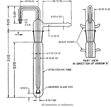
A-2.4.3 Water-Bath — A suitable cylindrical vessel 130 mm in inside diameter and 150 mm in depth. A cover to support the air-bath vertically shall be provided so that the sides and bottom of the air-bath are surrounded by a layer of water not less than 35 mm thick. The cover shall have an opening at a distance of 20 mm from the outer wall of the water-bath for suspending the bath thermo-meter. The air-bath, water-bath and water-bath cover may be made in one assembly as shown in Fig. 1.
A-2.5.2 Heat the wax sample to at least 10°C above its melting point by taking it in a test tube, kept in a water-bath, maintained at a temperature of not more than 20°C above the expected melting point of the wax.
A-2.5.3 Fill the test tube to a height of 50 mm with the molten sample. Insert the melting point thermometer through the centre of the cork in such a manner that the distance between the bulb of the thermometer and the bottom of the test tube is 10 mm. Keep the test-tube assembly in the air-bath while the temperature of molten wax in the test tube is still at least 10°C above its melting point.
A-2.4.4 Thermometer — range 50 to 100°C, least count 0.1°C conforming to Schedule Mark 22 of IS: 4825-1982*.
A-2.5 Procedure
A-2.5.1 Assemble the apparatus as shown in Fig. 1. Fill the water-bath to within 13 mm of the top with water at a temperature of 15 to 30°C. The bath temperature shall be maintained within these limits throughout the test.
*Specification for liquid-in-glass solid-stem reference thermometers (first revision).
A-2.5.4 Read the melting thermometer reading after every 15 seconds. Discontinue the test when five consecutive readings which agree within 0.1°C have been obtained or at least 3 min after the tem-perature begins to fall following a series of readings agreeing within 0.1 °C.
A-2.6 Calculations and Reporting
A-2.6.1 Average the five consecutive thermo-meter readings which include the least temperature change. Correct this average for error in thermo-meter scale, if necessary.
A-2.6.2 Report the result to the nearest 0.1°C as the paraffin wax melting point ( cooling curve ).
All dimensions in millimetres.
F I G . 1 ASSEMBLY OF APPARATUS FOR DETERMINING M F L T I N G P O I N T ( COOLING C U R V E ) OF PETROLEUM W A X
IS : 7401 - 1987
A-2.7 Precision — Results of duplicate tests shall not differ by more than the following amounts:
Repeatability Reproducibility
0.2°C 0.6°C
A-3. DETERMINATION OF LOSS ON DRYING A-3.1 Procedure — Weigh accurately about 10 g of the material and heat in a squat weighing bottle at 105 to 110°C. Cool and weigh till constant mass is obtained.
A-3.2 Calculation
Loss on drying, percent by mass = where
M = loss in mass in g, and
M1 = mass in g of the material taken for the test.
A-4. MEASUREMENT OF PENETRATION A-4.0 Outline of the Method — Penetration gives a measure of consistency of wax and is expressed in terms of the distance that a standard needle penetrates a sample of the material under standard conditions of loading, time and temperature. Penetration of wax is measured in mm by a stan-dard penetrometer needle after applying 200 g load for 4 min at 15 to 20°C.
A-4.1 Apparatus
A-4.1.1 Standard Penetrometer Needle — It is a Vicat needle of 1 mm2 cross section made from a
cylindrical steel rod 1.00 to 1.02 mm in diameter. The finished needle is hardened and highly poli-shed, and is mounted coaxially and centrally in a brass shank 3.2 mm in diameter, 20-25 mm long and finished as indicated in Fig. 2. The total length of needle protruding from the shank is approximately 32 mm.
All dimensions in millimetres.
F I G . 2 PENETROMETER NEEDLE
A-4.1.2 Penetrometer — As shown in Fig. 3, it has a rack and pinion operated dial, a stop and reset clock reading in half seconds, and an adjust-able mirror to facilitate setting the needle to 'touch point'. The depth of penetration is measured on a 360° dial in standard units of 1/10 mm.
NOTE — Alternatively, any similar apparatus which allows the needle to penetrate without appreciable friction, and which is accurately calibrated to yield results in accordance with the definition of penetration, may be used.
F I G . 3 PENETROMETER
A-4.2 Reagent
A-4.2.1 Rectified Spirit
A-4.3 Procedure
A-4.3.1 Preparation of the Sample — Allow the sample of paraffin wax to melt by putting it in water-oven (maintained at 90°C). Place the molten wax in a small chipboard box (4 cm3 size)
and cool it in a desiccator. The solid wax (4 cm3
size) is then taken out from the box, kept at 15 to 20°C for 24 hours and then subjected to the test.
A-4.3.2 Place the prepared sample on the stand of the penetrometer. Adjust the needle to make contact with the surface of the sample after ensuring that the needle has been washed with rectified spirit, dried and loaded with the specified mass. The total load exerted on the sample con-sists of the sum of the mass of the needle, the carrier, and the super-imposed mass and is 200 ± 0.25 g (accurate positioning of the needle is accomplished by placing the needle point in contact with its image reflected by the surface of the sample from a suitably placed source of light). Record and report the result in mm (taking the mean value).
NOTE 1 — For taking the reading of the dial, release the needle for 4 min, adjust the penetrometer and measure the distance to which the needle has penetrat-ed. Make at least three tests at points not less than 1 cm apart on the surface of the sample.
IS : 7401 - 1987
NOTE 2 — At the conclusion of the tests, clean the needle with rectified spirit and cotton wool and store in petroleum jelly.
A-5. DETERMINATION OF OIL CONTENT A-5.1 Scope — This method describes a test pro cedure for determination of oil in petroleum waxes having a congealing point of 30°C or higher and containing not more than 15 percent of oil.
A-5.2 Outline of the Method — The sample is dissolved in methyl ethyl ketone, the solution cooled to — 32°C to precipitate the wax, and filtered. The oil content of the filtrate is determined by evaporating the methyl ethyl ketone and weighing the residue.
A-5.3 Apparatus
A-5.3.1 Filter Stick and Assembly — It consists of a 10-mm diameter sintered glass filter stick* of
10 to 15 μ maximum pore diameter as determined by the method given in A-6 provided with an air pressure inlet tube and delivery nozzle. It is provided with a ground-glass joint to fit a 25 × 170 mm test-tube. The dimensions for a suitable filt-ration assembly are shown in Fig. 4.
NOTE - A metallic filter stick may be employed if desired. A filter stick made of stainless steel and having a 12.5 mm disc of 10 to 15μ maximum pore diameter has been found to be satisfactory. The metallic apparatus is inserted into a 25 × 150 mm test-tube and held in place by means of a cork.
A-5.3.2 Cooling Bath — It consists of an insu-lated box with 25 mm holes in the centre to accommodate any desired number of test-tubes. The bath may be tilled with a suitable medium, such as kerosene, and may be cooled by circula-ting a refrigerant through coils, or by using solid carbon dioxide. A suitable cooling bath to accom-modate three test-tubes is shown in Fig. 5.
All dimensions in millimetres. FIG. 4 FILTER STICK
*Suitable metal filter stick of desired porosity may be obtained from the Micro, Metallic Corporation, 30 Sea Cliff Avenue, Glen Cove, N.Y.A. A list of U.K. suppliers may be obtained from the Institute of Petroleum, 61 New Cavendish Street, London, England.
IS : 7401 - 1987
All dimensions in millimetres.
F I G . 5 COOLING BATH A-5.3.3 Dropper Pipette — provided with a
rubber bulb and calibrated to deliver 1.00 ± 0.05 g of molten wax.
A-5.3.4 Transfer Pipette — calibrated to deliver 15.00 ± 0.06 ml.
A-5.3.5 Air Pressure Regulator — designed to supply air to the filtration assembly ( see A-5.6.5 ) at the volume and pressure required to give an even flow of filtrate. Either the conventional pressure-reducing valve or a mercury-bubbler-type regulator has been found satisfactory. The latter type, illustrated in Fig. 6, consists of a 250-ml glass cvlinder and a T-tube held in the cylinder by means of a rubber stopper grooved at the sides to permit the escape of excess air. The volume and pressure of the air supplied to the filtration
assembly is regulated to a depth to which the T-tube is immersed in mercury at the bottom of the cylinder. Absorbent cotton placed in the space above the mercury prevents the loss of mercury by spattering. The air pressure regulator is connected to the filter stick and assembly by means of rubber tubing.
A-5.3.6 Thermometer — conforming to Schedule Mark 4 of IS : 2480 ( Part 1 ) 1983* or IS : 2480 ( Part 2 )-1982†.
*Specification for general purpose glass thermometers : Part 1 Solid stem thermometers (second revision).
†Specification for general purpose glass thermometers : Part 2 Enclosed-scale thermometers (second revision).
IS : 7401 - 1987
FIG. 6 AIR PRESSURE REGULATOR
A-5.3.7 Weighing Bottles — conical in shape and glass-stoppered, having a capacity of 15 ml.
A-5.3.8 Evaporation Assembly — consisting of an evaporating cabinet and connections, essentially as illustrated in Fig 7, and capable of maintaining a temperature of 35 ± 1°C around the evaporation flasks. Construct the jets with an inside diameter of 4.0 ± 0.2 mm for delivering a stream of clean, dry air vertically downward into the weighing bottle. Support each jet so that the tip is 15 ± 5 mm above the surface of the liquid at the start of the evaporation. Supply air at the rate of 2 to 3 litres per minute per jet, purified by passage through a tube of 1 cm bore packed loosely to a height of 20 cm with absorbent cotton. Periodically check the cleanliness of the air by evaporating 4 ml of methyl ethyl ketone by the procedure specified in A-5.6.6. When the residue does not exceed 0.1 mg, the evaporation equipment is operating satisfactorily.
A-5.3.9 Analytical Balance — capable of repro-ducing weights to 0.1 mg. The sensitivity should be adjusted so that 0.1 mg will deflect the pointer by half a division on the pointer scale.
A-5.3.10 Wire Stirrer— A piece of stiff iron or nichrome wire of about 1 mm diameter and 250 mm long. A 10-mm diameter loop is formed at each end, and the loop at the bottom end is bent so that the plane of the loop is perpendicular to the wire.
7
A-5.4 Solvent
A-5.4.1 Methyl Ethyl Ketone — Distilling be-tween 78 to 81°C and conforming to the following requirements. The material shall be stored over anhydrous calcium sulphate (5 percent by mass of the solvent) and shall be filtered before use.
Characteristic Requirement Colour Water white
Relative density, 20/20°C 0 805-0.807 Acidity, as acetic acid, percent by 0.003
mass, Max
Water content, percent by mass, 0.3 Max
Refractive index at 20°C 1.378 ± 0.002 Residue on evaporation of 4 ml 0.1(see Note)
of sample, mg, Max
NOTE — Residue on evaporation may be found out by the procedure described in A-5.6.6.
A-5.5 Sample — If the sample of wax is 1 kg or less, obtain a representative portion by melting the entire sample and stirring thoroughly. For samples over 1 kg, exercise special care to ensure obtaining a truly representative portion, bearing in mind that the oil may not be distributed uniformly throughout the sample, and that the mechanical operations may express some of the oil.
A-5.6 Procedure
A-5.6.1 Melt a representative portion of the sample in a beaker, using a water-bath or oven maintained at 70 to 100°C. As soon as the wax is completely melted, thoroughly mix by stirring. Preheat the dropper pipette in order to prevent solidification of wax in the tip, and withdraw a 1 g portion of the sample as soon as possible after the wax has melted. Hold the pipette in a vertical position, and carefully transfer its contents into a clean, dry test-tube, previously weighed to the nearest 1 mg (see Note). Swirl the test-tube so as to coat the bottom evenly with wax. This permits more rapid solution later. Allow the test-tube to cool, and weigh to the nearest 1 mg.
NOTE — The mass of a test-tube which is cleaned by means of solvents does not vary to a significant extent. Therefore, a tare mass may be obtained and used repeatedly.
A-5.6.2 Pipette 15 ml of methyl ethyl ketone into the test-tube and place the latter just up to the level of its contents in a hot water or steam-bath. Heat the solvent-wax mixture, stirring up and down with the wire stirrer, until a homoge-neous solution is obtained. Exercise care to avoid loss of solvent by prolonged boiling.
NOTE - Very high-melting wax samples may not form clear solution. Stir until the undissolved material is well dispersed as a fine cloud.
A-5.6.3 Plunge the test-tube into a 800-ml beaker of ice water and continue to stir until the con-tents are cold. Remove the stirrer. Remove the test tube from the ice bath, wipe dry on the out-side with a cloth and weigh to the nearest 0.1 g.
IS : 7401 - 1987
During this operation, solvent shall not be allowed to vaporize by more than 1 percent. The mass of the solv ent is, therefore, kept practically constant and after a few samples are weighed, this mass approximately 11.9 g, may be used as a constant factor.
A-5.6.4 Place the test-tube containing the wax-solvent slurry in the cooling bath which is main-tained at –34.5 ± 1°C During this chilling opera-tion, it is important that stirring by means of the thermometer be almost continuous, in order to maintain a slurry of uniform consistency as the wax precipitates. Do not allow the wax to set up on the walls of the cooling vessel nor permit any lumps of wax crystals to form. Continue stirring until the temperature reaches — 31.5±0.5°C.
A-5.6.5 Immerse in the mixture, the clean dry filter stick which has previously been cooled
by placing it in a test-tube and holding at — 34.5± 1°C in the cooling bath for a minimum of 10 minutcs. Seal the ground-glass joint of the filter so as to make an air-tight seal. Place an unstoppered weighing bottle, previously weighed, together with glass stopper to the nearest 0.1 mg, under the delivery nozzle of the filtration assembly.
NOTE — Take every precaution to ensure the accuracy of the mass of the stoppered weighing bottle. Prior to determining this mass, rinse the clean, dry, weighing bottle and stopper, with methyl ethyl ketone, wipe dry on the outside with a cloth, and place in the evapora-tion assembly to dry for about 5 minutes. Then remove the weighing bottle and stopper, place near the balance, and allow to stand for 10 minutes prior to weighing. Stopper the bottle during this cooling period. Once the weighing bottle and stopper have been dried in the evaporation assembly, lift only with forceps. Take care to remove and replace the glass stopper with alight touch.
8
All dimensions in millimetres.
IS : 7401 - 1987 A-5.6.6 Apply air pressure to the filtration
assembly, and immediately collect about 4 ml of filtrate in the weighing bottle. Release the air pressure to permit the liquid to drain back slowly from the delivery nozzle. Remove the weighing bottle immediately, and stopper and weigh to the nearest 10 mg without waiting for it to come to room temperature. Unstopper the weighing bottle and place it under one of the jets in the evapora-tion assembly maintained at 35 ± 1°C, with the air jet centered inside the neck, and the tip 15 ± 5 mm above the surface of the liquid. After the solvent has evaporated, which usually takes less than 30 minutes, remove the bottle, stopper, and place near the balance. Allow to stand for 10 minutes and weigh to the nearest 0.1 mg.
A-5.6.6.1 Repeat the evaporation procedure using a 5 minutes evaporation period instead of 30 minutes until the loss between successive weighings is not over 0.2 mg.
A-5.7 Calculation
A-5.7.1 Calculate the amount of oil in the wax as follows:
Oil content, percent by mass = — 0.15 where
A = mass in g of oil residue;
C = mass in g of solvent, obtained by subtract-ing mass of test-tube plus wax sample-(A-5.6.1) from the mass of the test-tube and contents (A-5.6.2);
B = mass in g of wax sample;
D = mass in g of solvent evaporated, obtained by subtracting mass of weighing bottle plus oil residue from the mass of weighing bottle plus the filtrate (A-5.6.5); and
0.15 = average correction factor for the solubility of wax in the solvent at — 31.7°C.
A-5.8 Reporting — Report the result as oil content, percent by mass; if the result is negative, report as zero.
A-5.9 Precision - Results of duplicate tests shall not differ by more than the following amounts:
Repeatability Reproducibility 0.06+8 percent of mean 0.2 + 11 percent of mean
A-6 METHOD OF TEST FOR MEASUREMENT OF MAXIMUM PORE DIAMETER OF RIGID POROUS FILTERS (See A-5.3.1) A-6.1 Scope — This method describes a test pro-cedure for determination of acceptability of porous filter sticks. This method establishes the maxi-mum pore diameter and also provides a means of detecting and measuring changes which occur from continued use.
A-6.2 Definition
A-6.2.1 Maximum Pore Diameter — Diameter in microns of the largest opening in filter.
NOTE — It is recognized that the maximum pore dia-meter as defined above does not necessarily indicate the physical dimensions of the largest pore in the filter. It is further recognized that the pores are highly irregular in shape. Because of the irregularity in shape and other phenomena characteristic of filtration, a filter may be expected to retain all particles larger than the maximum pore diameter as defined and determined herein, and will generally retain particles which are much smaller than the determined diameter.
A-6.3 Outline of Method
A-6.3.1 The filter is cleaned and wetted with water. It is then immersed in water and air pressure is applied against its upper surface until the first bubble of air passes through the filter. The maximum pore diameter is calculated from the surface tension of water and the applied pressure.
A-6.4 Apparatus
A-6.4.1 Manometer — mercury filled and reada-ble to 0.5 mm.
A-6.4.2 Air Supply — clean and filtered.
A-6.4.3 Air Pressure Regulator — needle-valve type.
A-6.4.4 Drying Oven
A-6.5 Procedure
A-6.5.1 Clean the filter sticks by soaking in con-centrated hydrochloric acid, and then wash them with distilled water. Rinse with acetone, air dry and place in drying oven at 105°C for 30 min.
A-6.5.2 Thoroughly wet the clean filter to be tested by soaking it in distilled water.
A-6.5.3 Assemble the apparatus as shown in Fig. 8. Apply pressure slowly from a source of clean air.
A-6.5.4 Immerse the filter just below the surface of the water.
NOTE — If a head of liquid exists above the surface of the filter, the back pressure produced shall be deducted from the observed pressure.
A-6.5.5 Increase the air pressure to 10 mm below the acceptable pressure limit and then at a slow uniform rate of about 3 mm of mercury per minute until the first bubble passes through the filter. This can be conveniently observed by placing the beaker or test tube over a mirror. Read the manometer when the first bubble passes off the underside of the filter.
A-6.6 Calculation
A-6.6.1 The pore diameter is calculated as follows :
where
D = pore diameter, in microns; and P = manometer reading, in millimetres of
mercury.
NOTE — From this equation, pressures corresponding to upper and lower limits of the specified pore diameters can be calculated. These pressures may be used for acceptance testing.
IS : 7401 - 1987
FIG. 8 ASSEMBLY OF APPARATUS FOR CHECKING PORE DIAMETER OF FILTER STICKS
BUREAU OF INDIAN STANDARDS
Headquarters:
Manak Bhavan, 9 Bahadur Shah Zafar Marg, NEW DELHI 110002 Telephones: 3 3 1 0 1 3 1 , 3311375
Telegrams: Manaksanstha (Common to all Offices)
Regional Offices: Telephone
Central : Manak Bhavan, 9 Bahadur Shah Zafar Marg, NEW DELHI 110002 3 3 1 0 1 3 1 , 3311375
*Eastern: 1/14 C.I.T. Scheme VII M, V.I.P. Road, Maniktola, CALCUTTA 700054 362499 Northern : SCO 445-446, Sector 35-C, CHANDIGARH 160036 21843, 31641
Southern : C.I.T. Campus, MADRAS 600113 412442, 412519, 412916 †Western: Manakalaya, E9 MIDC, Marol, Andheri ( East ), BOMBAY 400093 6329295
Branch Offices:
'Pushpak' Nurmohamed Shaikh Marg, Khanpur, AHMADABAD 380001 26348, 26349 Peenya Industrial Area, 1st Stage, Bangalore-Tumkur Road, BANGALORE 560053 384955, 384956
Gangotri Complex, 5th Floor, Bhadbhada Road, T.T. Nagar, BHOPAL 462003 66716
Plot No. 8 2 / 8 3 , Lewis Road, BHUBANESHWAR 751002 53627 5 3 / 5 Ward No. 29, R.G. Barua Road, 5th By-Lane, GUWAHATI 7 8 1 0 0 3 —
5-8-56C L.N. Gupta Marg ( Nampally Station Road ), HYDERABAD 500001 231083 R14 Yudhister Marg, C Scheme, JAIPUR 302005 63471, 69832
117/418 B Sarvodaya Nagar, KANPUR 208005 216876, 218292
Patliputra Industrial Estate, PATNA 800013 62305 T.C. No. 1 4 / 1 4 2 1 , University P.O., Palyam, TRIVANDRUM 695035 62104, 62117
Inspection Offices ( With Sale P o i n t) :
Pushpanjali, 1st Floor, 205A West High Court Road, Shankar Nagar Square, NAGPUR 440010
Institution of Engineers (India) Building, 1332 Shivaji Nagar, PUNE 4 1 1 0 0 5
25171 52435
*Sales Office in Calcutta is at 5 Chowringhee Approach, P.O. Princep Street, Calcutta 700072 †Sales Office in Bombay is at Novelty Chambers, Grant Road, Bombay 400007
276800 898528 Printed at Swatantra Bharat Press, Delhi (India)