UNF Digital Commons
UNF Graduate Theses and Dissertations Student Scholarship
2017
Extracting a Relational Database Schema from a
Document Database
Jared Thomas Wheeler
University of North Florida
This Master's Thesis is brought to you for free and open access by the Student Scholarship at UNF Digital Commons. It has been accepted for inclusion in UNF Graduate Theses and Dissertations by an authorized Suggested Citation
Wheeler, Jared Thomas, "Extracting a Relational Database Schema from a Document Database" (2017).UNF Graduate Theses and Dissertations. 730.
EXTRACTING A RELATIONAL DATABASE SCHEMA FROM A DOCUMENT DATABASE
by
Jared Wheeler
A thesis submitted to the School of Computing
in partial fulfillment of the requirements for the degree of
Master of Science in Computer and Information Sciences
UNIVERSITY OF NORTH FLORIDA SCHOOL OF COMPUTING
Copyright (©) 2017 by Jared Wheeler
All rights reserved. Reproduction in whole or in part in any form requires the prior written permission of Jared Wheeler or designated representative.
The thesis "Extracting a Relational Database Schema from a Document Database" submitted by Jared Wheeler in partial fulfillment of the requirements for the degree of Master of Science in Computer and Information Sciences has been
Approved by the thesis committee: Date
_________________________________________ Dr. Behrooz Seyed-Abbassi
Thesis Advisor and Committee Chairperson
______________________
________________________________________
Dr. Ken Martin ______________________
________________________________________
Dr. Roger Eggen ______________________
Accepted for the School of Computing:
________________________________________ Dr. Sherif Elfayoumy
Director of the School
______________________
Accepted for the College of Computing, Engineering, and Construction:
________________________________________ Dr. Mark Tumeo
Dean of the College
______________________
Accepted for the University:
_________________________________________ Dr. John Kantner
Dean of the Graduate School
ACKNOWLEDGEMENT
I took a long time to reach this point, to complete my thesis. I would like to thank my thesis advisor, Dr. Abassi, for his patience and assistance through all of my problems, as well as his experience and guidance for writing this document. Thanks to my thesis committee, Dr. Eggen and Dr. Martin, for their support and help to drive this to
completion. My thanks to Professor Schuller for giving me encouragement when I was at my wit’s end. And finally, to my friends, managers, coworkers, and family for their understanding and unending support.
CONTENTS
List of Figures ... viii
List of Tables ... xi
Abstract ... xii
Chapter 1 Background ... 1
Chapter 2 Core Concepts ... 11
2.1 Relationships ... 12 2.1.1 One-to-One Relationship ... 12 2.1.2 One-to-Many Relationship... 14 2.1.3 Many-to-Many Relationship ... 15 2.1.4 N-ary Relationships ... 17 2.2 Normalization ... 19
2.3 Structured Query Language ... 21
2.4 Document Databases ... 21
2.5 Variety ... 23
2.6 MongoDB ... 24
2.7 Node ... 24
Chapter 3 Methodology ... 27
3.1 One-to-One Relationship Transformation ... 29
3.2 One-to-Many and Many-to-One Transformations ... 31
3.2.1 One-to-Many Relationship Transformation ... 32
3.2.2 Many-to-One Relationship Transformation ... 34
3.2.3 One-to-Many Identifying Relationships ... 36
3.3 Many-to-Many Relationship Transformation ... 37
3.4 Data Types... 41 3.5 Output ... 42 Chapter 4 Implementation... 44 4.1 Variety ... 45 4.2 Duplication Detection ... 48 4.3 New Development ... 50
4.4 Relationship Structure Generation ... 51
4.5 Refine Relationships ... 55
4.6 Table Script Generation ... 57
4.7 Relationship Script Generation ... 58
4.8 Output ... 61
Chapter 5 Transformation Comparisons ... 63
5.2 One-to-Many Relationships ... 69
5.3 Many-to-One Relationships ... 73
5.4 Many-to-Many Relationships ... 76
5.5 Duplication in Depth ... 81
Chapter 6 Conclusions ... 88
6.1 Future Work for the Methodology ... 89
6.2 Future Work for the Implementation ... 90
6.3 Conclusions ... 93
List of References ... 96
Appendix A: Complete Source Code ... 100
Appendix B: Modified Variety Source Code ... 116
FIGURES
Figure 1 Sample Data in JSON ... 3
Figure 2 One-to-One Relationships ... 13
Figure 3 One-to-Many Non-Identifying Relationship ... 14
Figure 4 One-to-Many Identifying Relationship ... 15
Figure 5 Logical Many-to-Many Relationship ... 16
Figure 6 Many-to-Many Relationship ... 16
Figure 7 Unary Relationship ... 17
Figure 8 Ternary Relationship ... 18
Figure 9 Denormalized Client Schema ... 20
Figure 10 Normalized Client Schema ... 20
Figure 11 One-to-One Relationship Transformation ... 30
Figure 12 One-to-Many Non-Identifying Relationship Transformation ... 33
Figure 13 Many-to-One Non-Identifying Relationship Transformation ... 35
Figure 14 One-to-Many Identifying Relationship ... 36
Figure 15 Many-to-Many Document ... 39
Figure 16 Many-to-Many Relationship Transformation... 40
Figure 17 Variety Output Sample ... 46
Figure 18 Tracking of Duplicates ... 49
Figure 19 Variety Output with Duplication Detection ... 50
Figure 21 processField Function Overview ... 52
Figure 22 Relationship Object ... 53
Figure 23 Relationship Types ... 54
Figure 24 fieldInformation Object ... 55
Figure 25 propagateDuplication Function ... 56
Figure 26 Table Script Generation Overview ... 58
Figure 27 generateRelationshipScript Function... 59
Figure 28 generateManyToManyConstraint Function... 60
Figure 29 Sample Script Output ... 61
Figure 30 One-to-One Sample Document ... 65
Figure 31 One-to-One Generated Script ... 66
Figure 32 One-to-One DTOs ... 67
Figure 33 One-to-Many Sample Document ... 69
Figure 34 One-to-Many Generated Script ... 70
Figure 35 One-to-Many DTOs ... 71
Figure 36 Many-to-One Sample Document ... 73
Figure 37 Many-to-One Script ... 74
Figure 38 Many-to-One DTOs ... 75
Figure 39 Many-to-Many Sample Document ... 77
Figure 40 Many-to-Many Generated Script ... 78
Figure 41 Many-to-Many DTOs ... 79
Figure 42 Embedded Duplication Sample ... 82
Figure 44 Multilayer Sample Document... 85 Figure 45 Multilayer Generation Script ... 86 Figure 46 Duplicated Subdocument Chain ... 91
TABLES
Table 1 JSON vs XML ... 23
Table 2 Data Type Conversion ... 42
Table 3 JavaScript Data Types ... 47
Table 4 Relationship Type Derivation ... 57
Table 5 Serialized One-to-One DTO Comparison ... 68
Table 6 Serialized One-to-Many DTO Comparison ... 72
Table 7 Serialized Many-to-One DTO Comparison ... 76
Table 8 Serialized Many-to-Many DTO Comparison ... 80
Table 9 Embedded Duplication DTO Comparison ... 84
ABSTRACT
As NoSQL databases become increasingly used, more methodologies emerge for migrating from relational databases to NoSQL databases. Meanwhile, there is a lack of methodologies that assist in migration in the opposite direction, from NoSQL to relational. As software is being iterated upon, use cases may change. A system which was originally developed with a NoSQL database may accrue needs which require Atomic, Consistency, Isolation, and Durability (ACID) features that NoSQL systems lack, such as consistency across nodes or consistency across re-used domain objects. Shifting requirements could result in the system being changed to utilize a relational database. While there are some tools available to transfer data between an existing document database and existing relational database, there has been no work for automatically generating the relational database based upon the data already in the NoSQL system. Not taking the existing data into account can lead to inconsistencies during data migration. This thesis describes a methodology to automatically generate a relational database schema from the implicit schema of a document database. This thesis also includes details of how the methodology is implemented, and what could be
Chapter 1 BACKGROUND
Relational databases were first introduced in 1970 by E.F. Codd [Codd70]. Relational databases are based on set theory and relational algebra to store related data in a
structured manner. These databases consist of tables that are made of columns. Columns specify a data type which can be stored.
In database tables, columns can also have constraints. Constraints are criteria that must be fulfilled for a relational database to accept the data being inserted. Constraints can be that every record has a unique value, or if empty a default value is utilized. A
relationship is created through a foreign key constraint, which requires a record with the same value of that column to exist in another table. Information is retrieved from a relational database by querying a table, and performing joins on these relationships to correlate data between the tables.
Relational databases have been built upon as major products for technology giants, such as Oracle, Microsoft, and IBM. New feature sets and improvements are still being made to them as these technology giants push to service more needs. Relational databases are still the most widely used database today due to the reliability that relational database systems are known for.
Relational database systems are Atomic, Consistent, Isolated, and Durable, referred to as “ACID”. When a data source is ACID, it means that the transactions possess a specific set of properties [Date04]. The “A” stands for atomicity, which means that any changes to the data can be transactional, and therefore if any part of the transaction fails, the change does not take place.
The “C” is consistency, meaning the data will be valid according to rules in the system. These rules are primarily based on constraints, such as unique constraints and foreign key constraints, among others. Foreign key constraints are particularly important as they define the relationships between tables in a relational database. Without consistency, records could be dependent upon other records which no longer exist.
The “I” stands for isolation. Isolation is the property that transactions executing at the same time have no impact until they complete and commit. The “D” stands for
durability. Even if the system suffers a failure, such as crash or power outage, all completed transactions are preserved.
Since the turn of the century, with the rise of the Web 2.0 and Internet of Things, a movement away from relational databases has been emerging [Couchbase16]. The NoSQL Movement encourages the use of data structures other than relational database to store data. NoSQL stands for “Not only SQL” [Parker13], and has led to an environment of Polyglot Data, where multiple data storage technologies are utilized for a company’s needs [Young2013].
NoSQL represents a change in priorities for databases. The NoSQL databases no longer support all of ACID, but instead prefer responsiveness and flexibility. There are many varieties of NoSQL databases; however, this thesis will focus on the document database.
Document databases store unstructured data in a structure similar to JavaScript Object Notation (JSON), providing flexibility of schema [Couchbase16]. JSON consists of a series of key-value pairs. The values can be strings, numbers, arrays, or further JSON. In Figure 1, the Address field contains a sub-object in JSON. The sample JSON also has the field PhoneNumbers which holds an array of strings.
{
Name: 'John Doe', ContactInformation: {
PhoneNumber: '904-555-8648', Address: {
StreetNumber: '153', StreetName: 'Pine Lane' },
} }
Figure 1 Sample Data in JSON
Different document databases have minor variations upon the foundation of the JavaScript Object Notation (JSON) structure. For instance, MongoDB makes use of a format called Binary JSON (BSON), a compressed version of JSON for more efficient storage [MongoDB16B].
Document databases abandoned ACID in favor of BASE. BASE stands for Basic
Availability, Soft-state, and Eventual consistency [Sasaki15]. Basic availability indicates that the system will appear to be online most of the time. Soft-state has less constraining rules around consistency. Soft-state will allow data types of fields to change over time. Also, soft-state means that replicated objects can be temporarily inconsistent. Eventual consistency means that these inconsistencies will gradually be corrected in the long term. Therefore, the system still requires a way to make data synchronize over time, but it has a more flexible time period to do so than an ACID system would.
Following the BASE principals leads to a system with faster reads and writes under large loads because it has fewer constraints trying to protect the data. The BASE principles do, however, result in the loss of isolation, atomic transactions, and referential integrity [Boicea12].
Many document databases target heterogeneous distributed systems [Mohan13]. BASE makes distributed systems easier to utilize due to the eventual consistency, which indicates that all data across the cluster will eventually agree, although there might be some inconsistencies at specific points in time. These systems place a higher importance upon being relatively correct, but accessible, data as opposed to causing slow-downs in reads to ensure complete correctness.
The idea of the document databases embraces this change in philosophy, especially when it comes to utilizing the flexibility of JSON. Soft-state from BASE means that the system
will not constrain the data of the system. Instead, any structure can be saved in a document, as long as it does not violate any of the few requirements the system does have, such as maximum document size. Therefore, documents within a collection could potentially have a wide variety of field compositions. It is left to the application to handle the structure, null values, and potential differences in data type.
Document databases store JSON-like structures. JSON is quite literally a serialization format of objects. Document databases are storing serialized versions of objects as they could appear in the code of an application. This storage is similar to what Object
Relational Mappers (ORMs) do for applications on relational databases. Popular ORMs include Microsoft’s Entity Framework [Microsoft16] and Hibernate [RedHat16] for Java.
Object relational mappers take an input of a database schema and generate code that facilitates storing the data in that format. The classes generated by the ORMs are usually referred to as Data Transfer Objects (DTOs). The relational database forces the code to adapt to the database, and store in a format that the database will accept.
Document databases can be viewed as the opposite of a relational database when it comes to storing from code. The actual schema within a document database is not enforced by the system, but rather is adaptable to the data stored within it. Therefore, the schema is actually determined by the application that is utilizing it. More accurately, by the DTOs that the application uses to save to and extract data from the storage system. When a
schema is driven by the application, rather than the database, it is called an “implicit schema” [Gomez16].
The main difference between DTOs in an ORM and in a document database is how the storage handles the links between the objects. ORMs typically generate their classes as a class per table, then the classes hold references that account for the relationships within the database. Document databases, on the other hand, will store the related object(s) directly in the document being saved. These structures are referred to as embedded documents or a subdocument.
The actual structure of a document database is a group of collections. These collections store the previously referred to documents, similar to how tables store records
[MongoDB16D]. Documents can have subdocuments, which can have further subdocuments, nesting onward as many levels deep as the application requires. MongoDB supports up to 100 levels [MongoDB16C]. In addition to subdocuments, documents can store fields of a variety of data types, and arrays of fields or
subdocuments.
Document databases do not support references between documents, and has no concept of relational operations, such as joins. Instead, all data related to a document should be nested within the structure of that document. Therefore, it can become necessary for the same data to be inserted in multiple documents when it is shared. There are scenarios where if the data is updated in one document, it would need to be updated in all
documents that store the same information. Repetitively storing the same data through a database leads to inefficiencies in storage and potential update anomalies, which may result in denormalized data.
This was the scenario that a social media application called Diaspora encountered [Mei13B]. Diaspora was built on MongoDB, a popular document database. After reaching production, the creators encountered problems with subdocuments becoming inconsistent, when consistency was required. After several attempted solutions failed and new features required better consistency, the app was converted from utilizing MongoDB to use a MySQL relational database. The project manager noted the process by which their data was converted to be highly manual and problematic, especially in scenarios with a more denormalized structure [Mei13A].
There is no formalized method for transforming data from a document database into a relational schema [Goyal16]. Data migration from a document database into a relational database is currently handled by one of two methodologies, as described below.
The first method is to flatten the data and import it directly into the relational database. There are existing tools for document databases to export the contained data in a Comma Separated Value (CSV) file, which can then be imported into many modern relational database systems. Method one is a direct import from the CSV format into a single table.
Once the data is imported into the relational system, it can become difficult for the user to transform into the final data structure. The intermediary data structure may be sparse, in other words, full of empty columns. The sparsity of data is due to the ability of the document database to change its structure, leaving fields empty.
Also, it is likely for data to be duplicated across records. Because document databases cannot refer to data between documents, the data is copied or inserted new. These problems lead to difficulties querying data due to potentially large numbers of equivalent columns which must be included in filters or projections separately.
The second method is to create an intermediary format which the data from the NoSQL source could reside in as it is transformed from the original format into that of the final database. The moving of data can be done through custom tools built to transform the data for a specific pair of databases. However, the development process such a custom tool can be costly for the organization funding the work.
Alternatively, more general solutions can be found, such as Microsoft’s SQL Server Integration Services (SSIS). Despite using the general tool, the user must still have some technical knowledge to be able to architect the tables in the relational database. If the migration process is done incorrectly, data could be improperly associated or the relational system could suffer sparse and duplicate data, like in method one.
The difficulty of migrating the schema of the data from the document database source to a relational database target reveals that an expert in the data is required to determine an appropriate schema to be able to accurately migrate from a document database to a relational system. That expert must be proficient in database design to avoid the dangers of duplicate or sparse data, as neither methodology accounts for the design and creation of the destination database. The expert must also have strong knowledge of the domain that the system operates in, to be able to create the appropriate relationships of the target database.
A better methodology is needed that would automatically derive schema from the data of a document database to eliminate much of the need for an expert to create the database schema. Once the new schema is created, existing tools with friendlier interfaces could be used to migrate the data from the document database to the relational system. No tools or proposals exist today that perform automatic schema generation based on a document database.
A better methodology is needed that would automatically generate a relational database structure from a document database to ease the transition from document database to relational database. Document databases are popular, and some may argue overused [Dziruko15]. Relational database systems still have advantages when data is highly related or cases when ACID transactions are required. Relational databases are also more developed and integrated with common business software for reporting and analysis. If a
project wrongly chose to utilize a document database, the path back to other data models can be a painful one, as seen in the previously referred to Diaspora scenario [Mei13A].
In chapter two, more core ideas will be explained. Chapter three will feature an
explanation of the new methodology by which a relational schema can be automatically extracted from a document database. Chapter four contains details about the
implementation of such a system. Chapter five will offer an analysis of the results from running the system on a set of sample databases, and chapter six will offer conclusions and directions for future works.
Chapter 2 CORE CONCEPTS
The foundation of a relational database is the table. A table is made of a collection of columns and rows. Each column stores data in a predefined format. Each row, also referred to as record or tuple, in the table represents a set of data in the format defined by the columns. A primary key constraint can be defined on a column, or group of columns, to uniquely identify each row. A primary key is a column, or collection of columns, that is guaranteed to be unique and not null across all rows [W3Schools17]. A table can only have one primary key.
While rows within a single table are independent of one another, rows can be associated across different tables. The association of rows across multiple tables is referred to as a relationship. Tables can be related to one another through foreign key constraints. A foreign key consists of two columns, in separate tables, which are associated by the constraint. The constraint is associated directly to one of the tables. For the specified column in that table, referred to as the foreign key, to contain a value, that value must first exist in the specified column of the referenced table. This forces consistency between the tables related in the foreign key relationship. A table can have multiple foreign key constraints.
2.1 Relationships
The ability to relate data through foreign keys allows the database design to distribute data across multiple tables. The term “schema” is usually used to refer to the overall structure of the columns, tables, and relationships.
Cardinality of the relationship identifies how information within each table relates to information of other tables. Relationships can be described as one-to-one, one-to-many, or many-to-many, referring to how the data between tables can be related. The
definitions in sections 2.1.1 through 2.1.3 describe binary relationships, those consisting of two tables. Definition 2.1.4 will address relationships consisting of a size other than two tables.
2.1.1 One-to-One Relationship
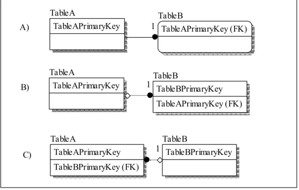
A one-to-one relationship specifies that for the relationship between two tables, there will only exist one row in each that will be related to one another. There are multiple ways to facilitate the to-one relationship in a database schema. Figure 2 features three one-to-one relationships, referred to as A, B, and C. A true one-one-to-one relationship is
demonstrated in A. The two tables share a primary key, therefore guaranteeing that only one record on each table will be related. The one-to-one guarantee is due to the unique requirement of primary keys, therefore the key can never be repeated in either table. The relationship between TableA and TableB is known as an identifying relationship, because
the primary key in TableA is also part of the primary key in TableB. The identifying relationship indicates that a record in TableB will never exist without a corresponding record in TableA.
Figure 2 One-to-One Relationships
The relationships in B and C are logically equivalent to relationship A, though less restrictive. The TableB in example B has the foreign key to TableA in a normal foreign key field, with no unique constraint. Therefore, it is physically possible for multiple records in TableB to relate to TableA; however logically it can be utilized as a one-to-one relationship. Example C is the same as relationship B, only the keys have been reversed. The key for Table. Relationships B and C physically facilitate a one-to-many
relationship. C) B) A) TableB TableBPrimaryKey TableA TableAPrimaryKey TableBPrimaryKey (FK) TableB TableBPrimaryKey TableAPrimaryKey (FK) TableA TableAPrimaryKey TableB TableAPrimaryKey (FK) TableA TableAPrimaryKey 1 1 1
2.1.2 One-to-Many Relationship
A one-to-many relationship allows for many rows in one table to be related to a single row in another table. In Figure 3, TableA and TableB have a one-to-many relationship. If TableB is filtered by the TableAPrimaryKey, then multiple records could be returned. Alternatively, if the same filter was applied to TableA, then only one record would be returned. Because TableB is associated to one record of TableA, but that same record in TableA is associated to multiple records of TableB, this is a one-to-many relationship.
Figure 3 One-to-Many Non-Identifying Relationship
Another variation of the one-to-many relationship is the identifying one-to-many relationship, shown in Figure 4. The difference between an identifying and a non-identifying relationship is the primary key of TableB, in the example. In the non-identifying relationship, the TableAPrimaryKey foreign key is above the solid line, indicating that it is part of the composite primary key. TableBPrimaryKey and TableAPrimaryKey are combined to serve as the primary key. TableAPrimaryKey still acts as a foreign key referring to TableA from TableB, but it also means that the data in TableB will not exist without the related data in TableA.
C) B) A) TableB TableBPrimaryKey TableA TableAPrimaryKey TableBPrimaryKey (FK) TableB TableBPrimaryKey TableAPrimaryKey (FK) TableA TableAPrimaryKey TableB TableAPrimaryKey (FK) TableA TableAPrimaryKey
Figure 4 One-to-Many Identifying Relationship
Unlike the one-to-one identifying relationship in Figure 2 A, the one-to-many identifying relationship requires TableB to have a composite key. Primary keys must uniquely identify a row. With only the TableAPrimaryKey as a primary key of TableB, there could only be one record in TableB with that value, which is the one-to-one relationship. The composite key allows multiple rows to exist for each value of the
TableAPrimaryKey value, therefore creating the one-to-many relationship.
2.1.3 Many-to-Many Relationship
A many-to-many relationship allows many rows from each table to be related to one another. Figure 5 shows the logical diagram of a many-to-many relationship. When the data of the two tables, TableA and TableB, are joined together, a user would be able to find multiple records of data in TableB using the TableAPrimaryKey as a filter. The user would also be able to find multiple records of data in TableA using the
TableBPrimaryKey. In the one-to-one and one-to-many relationships, the filtering of data was possible by one table holding the primary key of the other table in a foreign key; however a many-to-many relationship is handled differently.
TableB TableBPrimaryKey TableAPrimaryKey (FK) TableA TableAPrimaryKey C) B) A) TableB TableBPrimaryKey TableA TableAPrimaryKey TableBPrimaryKey (FK) TableB TableBPrimaryKey TableAPrimaryKey (FK) TableA TableAPrimaryKey TableB TableAPrimaryKey (FK) TableA TableAPrimaryKey
Figure 5 Logical Many-to-Many Relationship
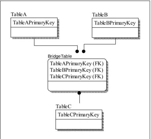
In standard relational databases, many-to-many relationships are not directly supported. Instead, a bridge table is created, which consists of two one-to-many relationships. The BridgeTable stores the primary keys from each of the tables in the many-to-many relationship. When the three tables are joined together, it gives the appearance of the many-to-many relationship. In Figure 6, if TableA or TableB were filtered based on the combinations within the BridgeTable, many records could be returned from each table. The possibility of many being returned from each makes it a many-to-many relationship.
2.1.4 N-ary Relationships
As the many-to-many relationship alludes to, while relational databases only support key constraints between two tables, there can be more complicated logical relationships. Logical relationships can be referred to as unary, binary, ternary, and up, or summed up as n-ary.
A unary relationship is when only one table is involved. The table has a foreign key which refers to is own primary key. Figure 7 shows how this relationship is built. TableA has the TableAForeignKey which refers back to the TableAPrimaryKey. Unary relationships are often used for hierarchical structures stored within a single table, such as employees with a relationship to their manager.
Figure 7 Unary Relationship
N-ary relationships start at the ternary relationship, which relates three tables. The relationship size then scales upward. The n-ary relationships are handled in the same way as a many-to-many relationship, with a bridge table. Figure 8 displays a ternary
TableA TableAPrimaryKey TableAForeignKey TableC TableCPrimaryKey BridgeTable TableAPrimaryKey (FK) TableBPrimaryKey (FK) TableCPrimaryKey (FK) TableA TableAPrimaryKey TableB TableBPrimaryKey C) B) A) TableB TableAPrimaryKey (FK) TableA TableAPrimaryKey TableA TableAPrimaryKey TableB TableBPrimaryKey TableAPrimaryKey (FK) TableB TableBPrimaryKey TableAPrimaryKey (FK) TableA TableAPrimaryKey
relationship. Like the many-to-many, the bridge table holds a key relating to each of the other tables.
N-ary relationships are the foundation for the star and snowflake schema patterns used in data warehousing. These schema feature a central bridge table, referred to as a fact table, which links many other tables with details [Date04].
Figure 8 Ternary Relationship TableA TableAPrimaryKey TableAForeignKey TableC TableCPrimaryKey BridgeTable TableAPrimaryKey (FK) TableBPrimaryKey (FK) TableCPrimaryKey (FK) TableA TableAPrimaryKey TableB TableBPrimaryKey C) B) A) TableB TableAPrimaryKey (FK) TableA TableAPrimaryKey TableA TableAPrimaryKey TableB TableBPrimaryKey TableAPrimaryKey (FK) TableB TableBPrimaryKey TableAPrimaryKey (FK) TableA TableAPrimaryKey
2.2 Normalization
With the ability to separate data across multiple tables, there comes a question of how to design the structure of the data. Normalization is the act of decomposing the data into tables that results in a more desirable structure with less duplication. Normalization is usually described by various normal forms. When the structure of a database satisfies certain sets of conditions, then it can be defined as belonging to a particular normal form. Common normal forms include first normal form, second normal form, third normal form, and Boyce/Codd normal form (BCNF) [Date04].
As a database schema becomes more normalized, the redundancies in data are
decomposed into other related tables. Normalization is typically used to spread data out for smaller writes to the database and reduce reading overhead when only a portion of data is necessary to be returned. When the tables are normalized, they could be denormalized again by joining the decomposed tables back together. Denormalized schema is faster to retrieve large sets of data, although can take up more storage space due to redundancies in data.
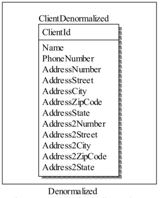
A sample of a denormalized schema in Figure 9, and a more normalized version of the same schema is in Figure 10. The fields in the denormalized schema beginning with “Address” were extracted into a one-to-many related table, reducing the complexity of the schema and increasing its flexibility. The denormalized schema would encounter
empty fields when a client only had one address. The normalized schema can have one or more addresses without any unintentional empty fields.
Figure 9 Denormalized Client Schema
Figure 10 Normalized Client Schema
Normalized Denormalized Address AddressId ClientId (FK) Number Street City ZipCode State ClientNormalized ClientId Name PhoneNumber ClientDenormalized ClientId Name PhoneNumber AddressNumber AddressStreet AddressCity AddressZipCode AddressState Address2Number Address2Street Address2City Address2ZipCode Address2State Normalized Denormalized Address AddressId ClientId (FK) Number Street City ZipCode State ClientNormalized ClientId Name PhoneNumber ClientDenormalized ClientId Name PhoneNumber AddressNumber AddressStreet AddressCity AddressZipCode AddressState Address2Number Address2Street Address2City Address2ZipCode Address2State
2.3 Structured Query Language
The Structured Querying Language (SQL) is the standard querying language for relational databases as defined by the International Organization for Standardization (ISO) and American National Standards Institute (ANSI) [Quality Nonsense17]. SQL consists of Data Definition Language (DDL) and Data Manipulation Language (DML).
DDL contains operations such as create and alter table, which specify the structure of the data in the database. DML contains operations such as insert, update, delete, and select, which manipulate the data within the structure of the database. With the select statement, users are able to retrieve data. An important option within the select statement is the join operation, which allows the query to gather data from multiple tables.
2.4 Document Databases
The document database is a NoSQL alternative to the traditional relational database. For the reasons covered in chapter one, document databases are designed to be highly
available caches of data. Document databases do not consist of tables, but rather collections.
Document databases are built of collections which hold root-level documents. These documents can hold fields, lists, and subdocuments. Subdocuments are additional
documents embedded within another document. Lists can consist of simple values or subdocuments [Gyorodi15].
The storage medium of choice for document databases is JSON, or JSON-like structures. JSON is a popular data-interchange format based on a subset of JavaScript [JSON16]. JSON is composed of key-value pairs which can store simple values, arrays, or further JSON objects.
JSON boasts a simplicity that other options, such as eXtensible Markup Language (XML), lack. While XML requires opening and closing tags for every element, JSON focuses on key-value pairs within curly braces. The lack of closing tags cuts back on the amount of data required to define values, especially of multi-layer structures.
Table 1 demonstrates the difference in length for the serialization of a small object which is composed of two properties, the second of which has multiple layers to it. In the example, the object serialized in XML is 148 characters, while the same object serialized in JSON is 83 characters. For these small sizes, the difference is minor, however, the scenario amounts to a 44% length reduction. If scaled to a larger object, the size difference would be similar.
JSON XML {object:{firstProperty:'value',seco ndProperty:{subProperty:{deepProper ty:'value'}}} <object><firstProperty>value</fir stProperty><secondProperty><subPr operty><deepProperty>value</deepP roperty></subProperty></secondPro perty> </object> Table 1 JSON vs XML 2.5 Variety
Chapter one referred to the implicit schema within a document database, created not by the database, but rather by the application that uses the database [Gomez16]. There have been previous attempts to explore the implicit schema. Most notable is an open source tool called Variety that was published to GitHub in 2012 [Dvorak16].
Variety is designed to examine a MongoDB data source and output metadata about the targeted collection. More specifically, Variety outputs information about the structure of the documents, the data types of the fields, and how frequently each field is present. How Variety determines the schema of the MongoDB will be expanded upon in chapter four. Variety is implemented in a JavaScript framework called Node, which will be covered in section 2.7.
2.6 MongoDB
MongoDB is one of the most popular document databases available to users. Rather than relying on JSON for storage, MongoDB utilizes Binary JSON (BSON), which is an extension of JSON [MongoDB16B]. BSON provides a more efficient storage mechanism, as well as expands on the data types that can be supported.
While document databases have abandoned ACID in favor of BASE, as discussed in chapter one, MongoDB has not left it entirely behind. MongoDB does support a limited form of transactions, where changes to a single document can be transactional when using a keyword [MongoDB16A]. MongoDB recommends a two-phase commit pattern be implemented within the application performing the actions if transactions are needed for anything beyond a single document.
2.7 Node
Node is a server-side JavaScript framework [Node16]. Node boasts a highly concurrent language through lack of locking. Node works because it runs on Google’s V8
JavaScript engine in a server-side environment, allowing Node programs to be run without a browser. This has made Node popular for small server-side tools.
Node is frequently used in conjunction with Express web server, AngularJS client-side, and MongoDB database. The combination of MongoDB, Express, AngularJS, and Node
is referred to as a “MEAN stack” [Leanos16]. Due to the common JavaScript functionalities of these technologies, the MEAN stack makes it simple to pass JSON objects between the layers. The MEAN stack is therefore favored by developers who are comfortable with JavaScript and wish to simplify the transferring of data between layers.
2.8 Entity Framework
Entity Framework, as previously mentioned, is an ORM for .NET. Entity Framework has three different modes: code-first, model-first, and database-first. Depending on the mode, Entity Framework will take a different set of inputs. By the end of the process, there will be a database set up with DTOs ready for the application to use.
For code-first, Entity Framework takes a series of DTOs as input. Therefore, the DTOs are created by the developer. Entity Framework will analyze the DTOs and determine an appropriate database schema. The database schema is then inserted into a specified database to prepare it for use with the application.
Entity Framework’s model-first database generation allows the user to use a database designer to visually create a database schema. Entity Framework will then generate both the database and DTOs for the application to use.
This thesis will utilize database-first Entity Framework during the methodology evaluation. In database-first, the user provides Entity Framework with a pre-existing
database. The developer must then specify what tables in the database require DTOs. Entity Framework then generates the necessary DTOs to represent those tables and their relationships.
Chapter 3 METHODOLOGY
What makes the described methodology unique is the automatic schema generation. Tools exist which can move the data into a work table or pre-existing schema for Extraction, Transformation, and Loading (ETL) activities, but none of these tools
automatically determine an appropriate schema to generate. The methodology described in this chapter derives a relational schema from the structure of a document database. The methodology assumes that the user is already able to extract or determine the implicit schema of the document. Determining the implicit schema may be done by using a tool such as Variety [Dvorak16], which will be described in section 4.1.
The problem that the methodology must overcome is determining the items that document databases do not explicitly track, namely relationships and data types. Determining the relationships between a document and its subdocuments, especially normalizing these relationships, is the more pressing problem. Without normalization, the final schema will facilitate duplicate data and unnecessary null fields, leading to wasted space in the database. Relationships between documents and subdocuments must be discovered and extracted into a relational table structure. Document databases do not have specified data types, therefore a strategy for associating a data type for each column must be created.
The methodology follows the idea that each document can be extracted into a relational table. Tables are generated from each field that contains a subdocument, therefore the name of that table will be the same as the field which stored the subdocument. This is the same for arrays of subdocuments. The name of the root table should be derived from the name of the collection in the document database. Therefore, when a document has a subdocument, the document and the subdocument become two tables with a relationship between them. The extraction of this relationship will lessen the sparsity of columns and decrease the amount of duplicate data.
To properly normalize the relationship between a document and its subdocument, the cardinality of the relationship must be determined. Once that has been determined, an appropriate relationship can be created within the database. The following defines how the methodology determines what kind of cardinality exists, and therefore what kind of schema should be generated.
In general, the relationship chosen depends on two factors: arrays and duplication. Document databases support documents having an array of subdocument. When an array exists, it indicates that multiple of the subdocument can be associated to a single of the parent document. Also, duplication of the subdocument will impact the relationship chosen. If an identical subdocument is present for multiple parent documents, then many parent documents are associated with that single subdocument. From these two pieces of knowledge, the cardinality of the relationship can be determined. From the cardinality, the appropriate schema relationship will be generated.
A series of steps will be repeated for all generated tables. When the schema for a new table is created, a primary key will also be generated. This will be an auto-incrementing integer for simplicity. All fields that are not subdocuments will be directly converted to columns on the table that represents that document.
3.1 One-to-One Relationship Transformation
A one-to-one relationship is found in a document database when a document contains a field which is a single subdocument, and that field is not duplicated in any other
documents. When the subdocument matches these criterion, it can be extracted into a one-to-one relationship for the generated schema.
The table derived from the document will have the primary key of the table derived from the subdocument added to it. The key originating from the subdocument will have a foreign key constraint referring to the table derived from the subdocument. This relationship constraint allows for the One-to-One relationship within the relational database.
This methodology for facilitating the one-to-one relationship is less constrained than if the two tables share a primary key, such as example A in Figure 2. However, a shared primary key implies a strong semantic relationship between the tables. Due to the generality of the methodology to be applied in many circumstances, it would be unwise to assume that this strong semantic relationship will always exist in one-to-one
relationships. Therefore, the author chose to err on the side of caution to avoid any such implications in the generated schema.
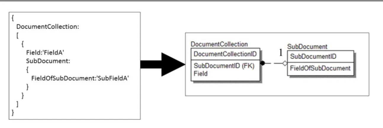
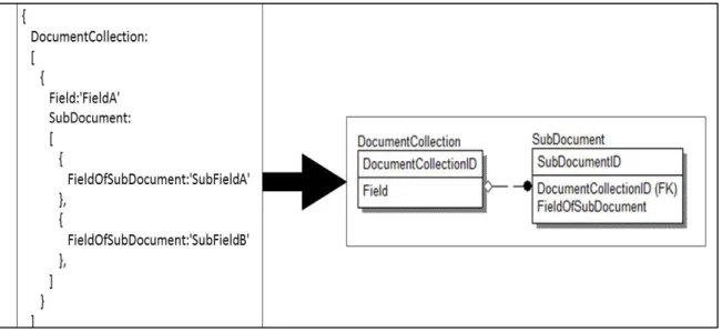
The transformation is demonstrated in Figure 11. Note that the field SubDocument is a single subdocument. Also, within the entire collection, it is not duplicated. These characteristics indicate the presence of a one-to-one relationship. The schema on the right links the documents such that each DocumentCollection will have a single
SubDocument. The columns are made from the other fields on its respective document.
Figure 11 One-to-One Relationship Transformation
Reviewing the sample in Figure 11, the source document contains a field called Field; this became the column Field on the DocumentCollection table. The source document also contains a subdocument in the field called SubDocument. The second table in the generated schema is named SubDocument, for the field that the subdocument was found in. The key that was generated for this relationship between the document and
subdocument is called SubDocumentID, also named after the field which held the subdocument. The key is also found on the DocumentCollection table to facilitate the
relationship between the tables. In the source document, the SubDocument field contains a field called FieldOfSubDocument; the field was transferred onto the SubDocument table in the generated schema. By joining these two tables, DocumentCollection and Subdocument, all of the data held in the original document would be retrieved.
3.2 One-to-Many and Many-to-One Transformations
In section 2.1.2, the one-to-many relationship was discussed as a relationship of one row in TableA correlating to multiple rows in TableB. When applying this idea to a
document database, it becomes clear that this description of a one-to-many relationship is incomplete.
In a relational database, there can exist a one-to-many relation from TableA to TableB, there can, alternatively, be a one-to-many relationship from TableB to TableA. In a relational database, both of these can be referred to as a one-to-many relationship, because direction is arbitrary.
A document, meanwhile, always starts at the top and moves into deeply nested layers. Therefore, order of the tables cannot be arbitrarily changed. A one-to-many relationship of TableA to TableB would be different from a one-to-many relationship of TableB to TableA. The second relationship can be described as a many-to-one relationship, which becomes necessary when describing the transformation of a document into a relational schema. Section 3.2.1 will discuss detection and handling of a one-to-many relationship.
Section 3.2.2 will expand on the many-to-one relationship, and how it differs from a one-to-many in detection and handling. Section 3.2.3 dives into the difficulties surrounding identifying relationships within one-to-many and many-to-one relationships.
3.2.1 One-to-Many Relationship Transformation
A one-to-many relationship is similar to the one-to-one relationship previously discussed. The difference is that the field within the document is actually an array of multiple
subdocuments. However, once more, all objects within the array must be unique to the document.
The table derived from the field will receive the primary key of the document table as an additional column. A foreign key constraint will be placed on the field table to refer to the document table. Figure 12 demonstrates a one-to-many relationship. Note that the SubDocument field is actually an array of subdocuments. The array indicates that there are multiple SubDocuments that will be related to a single parent document. However, there are no duplicates of the subdocument across the collection. Therefore, this example is a one-to-many relationship. With the generated schema, multiple SubDocument records can be associate to a single DocumentCollection record.
Figure 12 One-to-Many Non-Identifying Relationship Transformation
Reviewing the sample in Figure 12, the source document contains a field called Field; this became on the column Field on the DocumentCollection table. The source document also contains a subdocument in the field called SubDocument. The second table in the generated schema is named SubDocument, for the field that the subdocument was found in. The key that was generated for this relationship between the document and
subdocument is called SubDocumentID, also named after the field which held the subdocument. The key is also found on the SubDocument table to facilitate the
relationship between the tables. In the source document, the SubDocument field contains a field called FieldOfSubDocument; the field was transferred onto the SubDocument table in the generated schema. By joining these two tables, DocumentCollection and Subdocument, all of the data held in the original document would be retrieved.
3.2.2 Many-to-One Relationship Transformation
A many-to-one relationship exists when an identical subdocument is contained in the same field across multiple documents. Unlike the one-to-many relationship, no arrays are involved. In the many-to-one relationship, one subdocument is related to many instances of the parent document. To generate the appropriate schema, the primary key of the table derived from the subdocument will be added to the table derived from the document. The key that is present in both tables can then be related with a foreign key constraint.
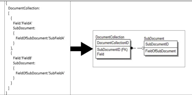
In Figure 13, both sample documents contain an identical subdocument, which is not part of an array. For the purpose of simplicity, the methodology searches for exact matches, so all present fields must have the exact same value. The sameness applies to all
subdocuments as well. So, the subdocument must be completely identical through all layers of subdocuments. If there exists a subdocument that is completely identical across multiple documents, then it is considered to be a duplicate.
Figure 13 Many-to-One Non-Identifying Relationship Transformation
Reviewing the sample in Figure 13, the source document contains a field called Field; this became on the column Field on the DocumentCollection table. The source document also contains a subdocument in the field called SubDocument. The second table in the generated schema is named SubDocument, for the field that the subdocument was found in. The key that was generated for this relationship between the document and
subdocument is called SubDocumentID, also named after the field which held the subdocument. The key is also found on the DocumentCollection table to facilitate the relationship between the tables. In the source document, the SubDocument field contains a field called FieldOfSubDocument; the field was transferred onto the SubDocument table in the generated schema. By joining these two tables, DocumentCollection and Subdocument, all of the data held in the original document would be retrieved.
3.2.3 One-to-Many Identifying Relationships
As with the one-to-one relationship, the one-to-many and many-to-one relationships can also be identifying in a relational database. A relationship is identifying when one table’s primary key contains the primary key of the other table in a relationship. Figure 14 shows an example of an identifying one-to-many relationship. TableB has a composite primary key of TableAPrimaryKey and TableBPrimaryKey. TableAPrimaryKey is also used in a foreign key relationship to TableA.
Figure 14 One-to-Many Identifying Relationship
Detecting the special scenario of an identifying relationship within a document database is a difficult scenario. An identifying relationship can be identified in a database by the composite key. Documents may or may not have identifiers in the subdocuments acting as links to the parent document. Dynamically determining that a field is both an
identifier and referring to the parent document becomes difficult, as naming could vary vastly. An additional requirement of an identifying relationship is that a record in the child table, TableB in the example, cannot exist without the parent.
TableB
TableAPrimaryKey (FK) TableBPrimaryKey TableA
Describing a data point as not being capable of existing without another is a powerful semantic statement. Even if it could be determined that a subdocument contains a reference to its parent document, there are still explanations other than an identifying relationship. For instance, the identifier could have existed on the objects to retrieve each other from a different data source, given that either object could be used as an input. It may be possible that a different document collection features the same document as a parent. There are many scenarios which would cause the identifier to be present on the child document without it being an identifying relationship.
To determine the existence of an identifying relationship requires at least two steps. First, there must be a reliable way to determine a field to be referring to the parent document. Second, it must be proven that the object that the subdocument represents cannot exist without the parent document. The second of these steps requires greater knowledge than what can be stored in a document database. Therefore, the methodology treats all relationships as non-identifying relationships.
3.3 Many-to-Many Relationship Transformation
The final relationship that must be transformed from document database to the relational database is the many-to-many relationship. The many-to-many relationship requires the use of a bridge table to accurately represent the logical relationship. The bridge table exists to represent the relationships possible between the two tables that have the
many-to-many relationship. The bridge table may have further information that is unique to each relationship; the methodology will not be taking advantage of that possibility.
A many-to-many relationship occurs in a document database when the field of a document holds an array of a subdocuments, and at least one of those subdocuments is duplicated across multiple documents. Similar to the many-to-one relationship,
duplication is judged by a subdocument having identical fields to another subdocument. The difference in a many-to-many relationship is that this duplicated subdocument exists within an array of subdocuments.
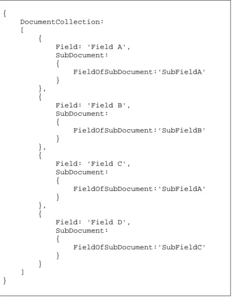
The collection of documents in Figure 15 depicts a subdocument that is duplicated across multiple documents. The field SubDocument holds an array of subdocuments. Both documents depicted in the example have a subdocument with the field
FieldOfSubdocument that has the value of ‘SubFieldA’. This common subdocument indicates the duplication.
{
DocumentCollection: [
{
Field: 'Field A', SubDocument: { FieldOfSubDocument:'SubFieldA' } }, { Field: 'Field B', SubDocument: { FieldOfSubDocument:'SubFieldB' } }, { Field: 'Field C', SubDocument: { FieldOfSubDocument:'SubFieldA' } }, { Field: 'Field D', SubDocument: { FieldOfSubDocument:'SubFieldC' } } ] }
Figure 15 Many-to-Many Document
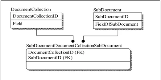
The tables in Figure 16 are derived from the document collection of Figure 15. The table generated for the parent document is called DocumentCollection, named for the name of the document collection, and a separate table for the subdocument, named for the field that contained it, SubDocument. Once more, a new ID will be automatically generated for each table to serve as the primary key. The field Field was generated on the
DocumentCollection table to mirror the parent document. FieldOfSubDocument was a field on the subdocument, and is therefore generated on the SubDocument table.
Figure 16 Many-to-Many Relationship Transformation
The primary keys of each table are copied to a new table, which will be the bridge table. The keys will provide a foreign key constraint to each of the tables, DocumentCollection and SubDocument, to form the many-to-many relationship. The two keys on the bridge table will become a composite primary key for the newly derived bridge table, meaning that the combination of the two must be unique.
In practice, bridge tables are usually named as a concatenation of the two tables it is bridging; the methodology follows that convention. The bridge table is named for the first table, followed by the second table. In Figure 16, the tables DocumentCollection and SubDocument are related through a bridge table, which is named
DocumentCollectionSubDocument using this convention.
SubDocumentDocumentCollectionSubDocument DocumentCollectionID (FK) SubDocumentID (FK) SubDocument SubDocumentID FieldOfSubDocument DocumentCollection DocumentCollectionID Field
DocumentCollectionSubDocument contains a composite primary key made of the DocumentCollectionID and SubDocumentID foreign keys. When all three tables are joined together, the data of the document collection can be recreated.
3.4 Data Types
For anything within the document database to be transformed at the physical level, it must first be determined what exists within the collections of the document database. Through analysis of the data, it can be determined what data types exist in each field and if that field should be nullable within the derived relational physical schema.
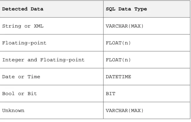
With the discovered data types, if they are consistent, then an equivalent data type should be used within the generated schema. For instance, integer fields stored in a BIGINT column or a float field stored in a FLOAT column. An unknown data type is stored in a VARCHAR(MAX). Further details are found in Table 2.
Detected Data SQL Data Type
String or XML VARCHAR(MAX)
Floating-point FLOAT(n)
Integer and Floating-point FLOAT(n)
Date or Time DATETIME
Bool or Bit BIT
Unknown VARCHAR(MAX)
Table 2 Data Type Conversion
3.5 Output
The output of the methodology will be the scripts for the creation of a database which would be able to receive the data from the document database. This database will have the subdocuments of the collection extracted out into additional tables to lessen the amount of null or duplicated data. With the use of normalization, the schema will provide a more efficient storage structure.
Chapter four describes how Variety, a schema analyzer for MongoDB, was utilized to determine the implicit schema of the document database, and the necessary modifications that were made to detect duplicate data. Chapter four will also describe how the
methodology was used for the transformation of a document database to a relational database. Chapter five presents the results of several tests for the conversion software. Chapter six provides conclusions and further ideas for future work.
Chapter 4 IMPLEMENTATION
The methodology described in chapter 3 generates a relational database schema from a document database. The schema generation is based upon the implicit schema of the document collection; however the methodology does not give a specific way by which the implicit schema should be derived. The information in the implicit schema consists of the arrangement of the fields and subdocuments, data types, and what fields contain duplicated values.
The implementation in this chapter offers a tool to solve the problem of retrieving the implicit schema. Variety is a schema generator for MongoDB written in Node
[Dvorak16]. Variety takes in the name of the collection to be mapped, and then outputs a JSON object that describes the schema of the documents in that collection. Once the implicit schema is defined, the methodology described in chapter 3 generates a relational schema from a source document database.
Section 4.1 will cover how Variety works, and the structure that it creates. Section 4.2 introduces a solution to the one gap that Variety leaves in the metadata about the
document database. Within section 4.3, the output of Variety is consumed by the system to generate the metadata to be used in table generation. Section 4.4 shows the final tweaks that need to be made before the system is ready to generate the schema. Sections
4.5 and 4.6 cover how the system generates scripts for table creation and foreign key relationships, respectively.
4.1 Variety
Variety is an open source software designed to determine the implicit schema of a document collection. Variety takes an input of a MongoDB connection, as well as some settings. Variety outputs a JSON object that describes the structure of the document collection.
Figure 17 contains a sample of the metadata that Variety outputs. The _id nested object provides a key which contains the object path of the field that it is describing in this object. The example features address.building and address.street. These examples indicate that from the root document, there is a subdocument called address. On that subdocument, address, are the fields: building and street.
The key is used as the identifier for the field being described by Variety. If Variety encounters an array datatype, it uses a placeholder string for the key of that field. The placeholder string acts as an anonymous object to differentiate between the field which contains an array and the unnamed document which exists within the array.
{ "_id" : { "key" : "address.building" }, "value" : { "types" : { "String" : 25360 } }, "totalOccurrences" : 25360, "percentContaining" : 100 }, { "_id" : { "key" : "address.street" }, "value" : { "types" : { "String" : 25360 } }, "totalOccurrences" : 25360, "percentContaining" : 100 },
Figure 17 Variety Output Sample
Next, the value property of the output sample describes the data types that exist in the field being described. In the sample, both address.building and address.street contain 25360 instances of data of the type String. The properties in the types object describe the data types. Variety relies on the JavaScript language function typeof to determine the data type. Table 3 lists the data types in JavaScript and the return value from typeof function [Mozilla17B]. Therefore, anything in the result column is a valid property name on the types object.
Type Result Undefined "undefined" Null "object" Boolean "boolean" Number "number" String "string"
Symbol (new in ECMAScript 2015) "symbol"
Function object (implements [[Call]] in ECMA-262 terms)
"function"
Table 3 JavaScript Data Types
Variety derives this information by extracting all of the data out of the targeted
MongoDB collection, and then running a reduce on it. Reduce is a method in JavaScript that will take a collection of data and perform an action on every item to generate one single return object that in some way represents the entire collection [Mozilla17A].
The reduce iterates over each document in the collection, processing it and updating the metadata that will become the output information. During each iteration, Variety determines the data type of the field in the particular document and either adds it to the metadata or increments the counter. When the reduce completes, the output is a
fully-formed set of metadata. The metadata describes the structure of the document collection. The metadata includes object graphs, nullability, and datatypes.
The methodology requires an input with data about the document structure, data types, nullability, and where duplication exists. The output from Variety can be interpreted to obtain all of these required inputs, except for if duplication exists. Metadata about where duplication exists is important because it will be used by the methodology to determine if a many-to-one or many-to-many relationship exists.
Variety is an open source software under an MIT license, which allows for distribution and modification of the source code [OpenSource.org17]. With some minor
modifications to Variety, the required information about duplicated subdocuments can be combined with Variety’s already useful output.
4.2 Duplication Detection
During the reduction of the collection, the system tracks all previous values for each field. Upon the first duplicate being encountered, the field is flagged as having duplicates and the cache of previous values is dumped. The dump is to attempt to preserve memory as it is possible for the data being processed to be large.
Once the field is flagged as having duplicates, it is no longer checked. The code for tracking duplicate values is depicted in Figure 18. If no previous duplication has been
found, the current value being processed is checked against the array of previous values. If the value is a duplicate, then the field is marked as having duplicates in the
duplicationTracking array. If the value is not a duplicate, the value for the field is inserted into the values array.
if(duplicationTracking[key] === false){ if(values[key].values.indexOf(value.toString()) >= 0){ duplicationTracking[key] = true; values[key].values = []; }else{ values[key].values.push(value.toString()) } }
Figure 18 Tracking of Duplicates
Later, when the metadata is being used to generate Variety’s output, the duplicationExists property is added to the output. The duplicationExists property exists for each field in the Variety metadata, allowing the system to determine if the document as a whole is
duplicated in the collection. If all fields on a document has the duplicationExists property set to true, then the system will treat that document as being able to have duplicates. The duplication represented impacts the kind of relationship chosen by the methodology. The addition of the duplicationExists property will alter the output of Variety from the structure in Figure 17 to that of Figure 19. Every field object has the duplicationExists property after the modifications.
{ "_id" : { "key" : "address.building" }, "value" : { "types" : { "String" : 25360 } }, "totalOccurrences" : 25360, "percentContaining" : 100, "duplicationExists" : true }, { "_id" : { "key" : "address.street" }, "value" : { "types" : { "String" : 25360 } }, "totalOccurrences" : 25360, "percentContaining" : 100, "duplicationExists" : true },
Figure 19 Variety Output with Duplication Detection
In cases where a document is in a many-to-one or many-to-many relationship,
duplicationExists will be true on all fields. When the document is in a to-one or one-to-many relationship, all fields will have duplicationExists set to false.
4.3 New Development
The system begins by executing the modified version of Variety and receiving the JSON structure in Figure 19. Upon return of the completion of Variety’s run, Figure 20 depicts the code that is executed. This consists of four methods which are executed in sequence
to generate the schema: processField, refineRelationships, generateTableCreationSql, and generateRelationshipSql. At the end of processing, the createScript and alterScript are concatenated, and sent to the connected database.
function postPromise(){
var schemaAnalysis = JSON.parse(global.varietyResult); schemaAnalysis.forEach(processField);
refineRelationships();
var createScript = generateTableCreationSql(); var alterScript = generateRelationshipSql(); }
Figure 20 Implemented Methodology
Section 4.4 will cover what happens during the processField method. The
refineRelationships method which determines the cardinality of the relationships will be covered in section 4.5. Section 4.6 will cover the generateTableCreationSql method. Section 4.7 will explain the generateRelationshipSql method.
4.4 Relationship Structure Generation
The processField method is responsible for most of the heavy lifting of the system. The method will execute on each field that Variety provides metadata for, and generate new metadata that describes the tables and relationships.
The core of the method processField is embodied by the pseudocode in Figure 21. Due to the flat structure that Variety outputs, the system relies upon the _id.key of each field.