Hardware Security of the Controller Area Network (CAN Bus)
David Satagaj
A Senior Thesis submitted in partial fulfillment of the requirements for graduation
in the Honors Program Liberty University
Acceptance of Senior Honors Thesis This Senior Honors Thesis is accepted in partial fulfillment of the requirements for graduation from the
Honors Program of Liberty University.
______________________________
Feng Wang, Ph.D. Thesis Chair
______________________________
Kyung Kyoon Bae, Ph.D. Committee Member
______________________________
David Schweitzer, Ph.D. Assistant Honors Director
______________________________
Abstract
The CAN bus is a multi-master network messaging protocol that is a standard across the
vehicular industry to provide intra-vehicular communications. Electronics Control Units within vehicles use this network to exchange critical information to operate the car. With the advent of the internet nearly three decades ago, and an increasingly inter-connected world, it is vital that the security of the CAN bus be addressed and built up to withstand physical and non-physical intrusions with malicious intent. Specifically, this paper looks at the concept of node identifiers and how they allow the strengths of the CAN bus to shine while also increasing the level of security provided at the data-link level.
Hardware Security of the CAN Bus Introduction
The Controller Area Network is a network messaging protocol that allows a variety of devices such as microcontrollers or other small computers to communicate without the help of a master or host computer. First developed in the 1980s for interconnecting electronic components in automobiles, this communications protocol reduced previously hardwired connections to a simple two wire system (Farsi, Ratcliff, & Barbosa, 1999). Because of its minimal wiring, the CAN bus has spread to industrial equipment, small electric bikes, and many other uses. This communications protocol is commonly referred to as the CAN bus and will be referred to as such henceforth in this paper. The CAN bus is considered a half-duplex system, meaning that devices can communicate with one another, but not simultaneously. Due to hardware limitations, 110 nodes can be linked together using this protocol, however there is a higher theoretical limit.
Background of CAN
The CAN bus is an excellent solution for many industries due to its two-wire physical implementation. This puts much greater impetus on the software, where greater complexity can be achieved in the same physical space. While there is still a limit to the achievable software, the world has seen great technological advancement in the past few decades and it will continue to see technology advance and memory sizes and data transfer speeds improve. In order to gain a full appreciation of the uses and intricacies of the CAN bus, a full overview shall be given on both the physical and software levels. This overview is given due to the advancement of current technology and the threat that it poses to general network security it automotive vehicles. As vehicles that use the CAN bus continue to become connected with the Internet, the potential for
maligning the purpose of the CAN bus to the detriment of the occupants of the vehicle becomes exceedingly real. After the overview of the CAN bus, an overview of past, current, and future threats will be given to demonstrate what the automotive industry must face in the coming years. After that, one specific issue will be focused on and a potential solution will be proposed that will help address some of the security concerns expressed earlier in the paper.
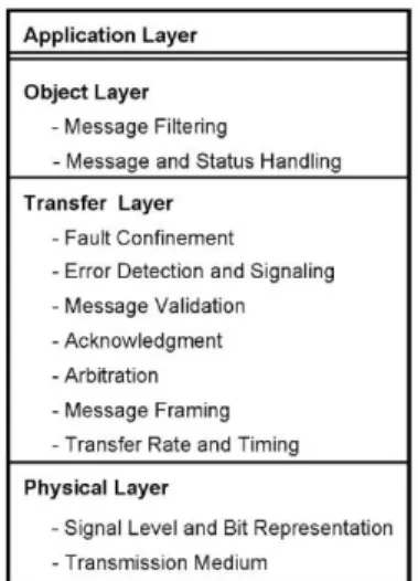
The protocol has a four-layer protocol similar to the OSI model. It makes use of the physical, transfer, object, and applications layers as shown in Figure 1 (Othman, Aji, Fakhreddin, & Al-Ali, 2006).
Figure 1. Explanation of the CAN bus layer scheme. Reprinted from "Controller area networks: Evolution and
applications" by H.F. Othman, Y.R. Aji, F.T. Fakhreddin, and A.R. Al-Ali, 2006, 2nd International Conference on
Information & Communication Technologies, p. 3088-3093. Copyright 2006 by IEEE. Used by permission.
Using the standard OSI model, this is known as the physical, data link (which
encompasses the object and transfer layers), and application layers. As shown in Figure 1, the application layer is where the user manipulates and utilizes the CAN bus. The object and transfer layers combine to form the data link layer from the traditional OSI model. The object layer is used for the distinction of messages: both filtering handling. The transfer layer has the widest
breadth of responsibilities, with error detection, fault confinement, validation, acknowledgment, and other essential syntax and validation duties being performed on this level. The physical layer is responsible for the actual bit level transportation. The CAN specification in its original form written by Robert Bosch (2011) details only the Data link and Physical layers of the OSI (Open Systems Interconnection) model. The OSI model involves seven distinct layers that define the implementation of communications while primarily ignoring the actual technology underlying the protocol. The primary purpose of the physical layer is to, “define the encoding of bits into (electrical or electromagnetic) signals with defined physical characteristics” (Di Natale, 2012, p. 1). Because of the nature of the CAN protocol, the bits can be encoded on either wireless or wired links from one node to another. However, the original Bosch standard only defined the bit timing, encoding, and synchronization. This leaves the required current and voltage levels, the connectors, and other characteristics that are necessary for the definition of the driver, receiver and physical wiring undefined. Later, the International Organization for Standardization (ISO) extended the original specification to include implementation of the physical layer as well as a discussion of the transfer and application layers, thus allowing for a fully implementable CAN bus protocol. The Data link layer is made up of the Logical Link Control (LLC) and Medium Access Control (MAC) layers. Primarily, the LLC provides services for transmission including remote data request, conditions for accepting messages (message filtering), and ways to
implement recovery and flow management, which is called overload notification (Di Natale, 2012). The MAC layer is essentially the kernel of the CAN bus, responsible for message framing, arbitration of the medium, acknowledgment, and error detection signaling. Physical Layer
To gain a better appreciation for the usage and purpose of the physical layer, it is important to turn to the original Robert Bosch (2011) specification. This specification was rewritten to include a flexible data rate, allowing for data speeds greater than one megabit per second and messages longer than eight bytes per frame. The changes do not affect the physical layer, so the same specifications are used. Primarily, “the Physical Layer handles bits and defines how signals are actually transmitted” (Bosch, 2011, p. 4). To delve further into this, the physical layer handles synchronization, bit timing, and bit encoding. As this is a communications
protocol, the underlying electronics of the mode of transmission and the nodes is left undefined in order to allow for specialization for each application. Therefore, while a certain network must have uniformity across all nodes in the implementation of the physical layer, different networks might have different implementations that share only the concepts outlined (Bosch, 2011).
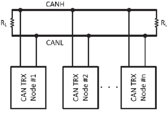
One implementation, which can be seen in Figure 2, demonstrates how the CAN bus is a multi-master system, with multiple nodes being both TX (talking) and RX (sharing) nodes. The CANH is the high signal and the CANL is the low signal. The resistors on each end of the CAN bus are normally a standardized 120 Ω, which allows the nodes to differentiate between a high and a low, or a binary zero and one with the zero being high and the one being low (Kang, Seong, & Lee, 2018). As the CAN bus is a multi-master system, it is vital that a priority-based system be implemented. The protocol uses a priority addressing which shall be discussed in greater detail later. Because of the addressing and two wire system, each node must be able to listen for the bit pushed by other nodes. This means that each node must transmit their bit for a long enough period of time such that the electrical signal can propagate down the entire network. This is a limitation imposed on the CAN bus which must be followed, or the user could suffer
from faulty or overwritten data. As a general rule, the maximum data rate is 1 megabit per second for a network 40 meters or less in length and 125 kilobits per second for a network 500 meters or less (Burns & Davis, 2013).
Figure 2. Diagram of Physical CAN bus implementation. Reprinted from "Controller area network with flexible
data rate transmitter design with low electromagnetic emission" by S. Kang, J. Seong, & M. Lee, 2018, IEEE
Transactions on Vehicular Technology, p. 7290-7298. Copyright 2018 by IEEE. Used by permission.
Another feature of the physical layer is synchronization. The CAN bus implements this in a fairly simple way. Nodes are not allowed to begin a transmission while another node is
transmitting. This means that when a node starts to transmit the beginning of their inter-frame space and their priority, all other nodes (even those about to or beginning to transmit)
synchronize with the leading edge of the dominant start of frame bit (which is a zero) (Burns & Davis, 2013). The overall signal type is of the Non-Return to Zero (NRZ) encoding. This signal type ensures that there is a high resilience to external disturbance through the use of a recessive and dominant state (with a logical zero being dominant). Another benefit to this bit encoding is that there are a minimum number of transitions: times when the bus state changes from dominant to recessive or vice versa. This is necessary for synchronization and timing. Another way the
CAN bus protocol accomplishes this is through the use of bit stuffing, which is implemented in the data link layer and will be discussed further in that section (Di Natale, 2012).
Data Link Layer
The data link layer is the second main layer from the OSI protocol that is defined in the original and revised CAN bus and CAN FD bus specifications. This layer can be alternatively referred to as the transfer layer, and is comprised of two sublayers, the Logical Link Control and the Medium Access Control. The overall purpose of the data link layer is to build off the physical layer by implementing procedures and protocols for data delivery. In essence, this means that a data link layer is created to handle collisions, correct possible errors from the physical layer, and general data delivery. This is true of most data link layers across other technology and is not extremely different within the CAN bus specifications. Some of the differences include frame bit stuffing and destuffing, serialization, and acceptance filtering (Bosch, 2011). This next section looks at a more in depth look of the two distinct sections of this data link layer.
Logical Link Control. The Logical Link Control sublayer of the CAN bus is responsible for message filtering, overload notification and recovery management. In essence, this means that it provides the logic sifting through received messages for ones that should be accepted, to implement remote data requests, to provide messages to the MAC sublayer to be transmitted, and to send overload notifications. This layer is essentially the gatekeeper for the Data Link Layer. Each CAN bus frame has an identifier included in the header portion of the message. This identifier, which will be covered more in the CAN Message Frames section, does not indicate a specific destination for a message, but instead provides information about the contents such that other nodes can determine whether or not they should accept and act on the data. This decision to
accept or ignore the message is implemented in the Logical Link Control and called Message Filtering (Bosch, 2011).
In some cases, a node will request a message of a certain type from the CAN bus. The Logical Link Control sublayer sends a message frame to the MAC sublayer. The identifier of the message frame indicates the identifier of the requested message, the data field is completely empty, the Data Length Code (DLC) field indicates the length of the data of the requested message, and the Remote Transmission Request (RTR) bit of the arbitration field must be set to recessive (a logical one) (Di Natale, 2012). Similar to Remote Data Requests, the Logical Link Control Layer implements overload messages based on three different conditions: internal conditions, the detection of a dominant bit as the first or second bit of the bus intermission (the space on the bus in between transmissions), or a given node receiving a dominant bit as the last bit of an error delimiter or overload delimiter.
Medium Access Control (MAC). The MAC sublayer of the Data Link Layer can be summarized as the kernel of the CAN bus. As previously mentioned, it is responsible for some of the core responsibilities of the CAN bus, including, “message framing, arbitration,
acknowledgment, error detection, and signaling” (Bosch, 2011, p. 4). Arguably, a defined
message format is the most important aspect of the CAN bus, and there are four possible formats under the current CAN specification. These can be found in Figure 3. A unique frame identifier is given to each command possible on the CAN bus from all nodes. Messages with a lower number have a higher precedence due to a logical zero being the dominant signal.
Figure 3. CAN Format Types. Reprinted from "CAN FD specification" by R. Bosch, 2011, Robert Bosch GmbH.
Copyright 2011 by Robert Bosch GmbH. Used by permission.
The arbitration of the messages sent on the CAN bus is achieved through simple protocol definition. When the bus goes through an idle period, any unit is allowed to start a transmission. If multiple nodes begin transmitting at the same time, then the identifier is used to determine who has priority. Because zero is the dominant value, when each bit of the identifier is
transmitted, the bus is pulled to the dominant value. Each transmitting node checks the current value of the overall bus against the specific bit of the identifier, and if they do not have priority, then their transmission ceases and they begin listening to the message of the dominant node. This creates a global priority-based queue that forces messages to be sent according to a fixed priority, non-pre-emptive schedule.
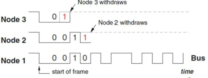
In Figure 4, a bit-by-bit view of the arbitration process can be seen. Nodes 1, 2, and 3 have differing priorities, and at the start of the frame, they each begin transmitting their message (beginning with the identifier). As all three messages begin with a dominant bit (logical zero) for their priority, no node is eliminated, but during the second bit transmission, node 3 withdraws and becomes a receiver because it transmits the recessive bit (logical one). This occurs again because each node might have its own clock that is synchronized with the master, the arbitration process also begins with a re-synchronization to the leading edge of the start-of-frame bit of the first transmitting node (Davis, Burns, & Bril, 2007). The acknowledgment, error detection, and
signaling portion are implemented instrumentally in the MAC layer, as all receivers are coded to check consistency and respond with either an error or an acknowledgment. Error detection has been implemented through cyclic redundancy checks (CRC), bit stuffing, and message frame checks. Cyclic redundancy checks are a sequence of bits that help determine whether there are errors in the message frame. Bit stuffing is introduced to ensure the CAN high and low signals maintain an average that can differentiate new signals without error. These methods allow minimal errors and encourage high reliability in the CAN bus.
Figure 4. Demonstration of CAN priority messaging in action. Reprinted from "Understanding and using the
controller area network communication protocol theory and practice" by M. Di Natale, 2012Springer. Copyright
2012 by Springer Science+Business Media. Used by permission.
Application Layer
The Application Layer is not defined in the Bosch specification document (Bosch, 2011), however it is commonly included in papers and discussion related to the CAN Bus because it is the layer in which the user can access and make use of the CAN bus (Othman et al., 2006). To give some idea of the differing applications, it is possible for a gateway to be implemented that connects the CAN bus with higher layer protocols in order to provide a measure of interaction
with the user. This translation of data from CAN bus to a different protocol happens on the application layer (Di Natale, 2012).
CAN Message Frames
The message frame definition of the CAN bus is necessary to ensure that all nodes operating on the network can understand each other and defer when they are supposed to. There are four distinct types of messages that can be sent over the tradition CAN bus definition. These are the Data Frame, the Remote Request Frame, the Error Frame, and the Overload Frame. All frames share the same general format, with slight variations. The data frame contains
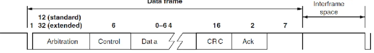
information (data) from a source to one or more receivers. One data frame has seven distinct fields that are ordered to allow for efficient communications. The fields are Start of Frame, Arbitration, Control, Data, CRC, Ack, and End of Frame and a physical representation of it can be seen in Figure 5. The data field contained within the message can be anywhere from one to eight bytes long, though some implementations pad messages that are less than eight bytes in order to achieve consistency.
Figure 5. Current CAN bus data frame. Reprinted from "Understanding and using the controller area network
communication protocol theory and practice" by M. Di Natale, 2012 Springer. Copyright 2012 by Springer
Any node can begin to transmit a new frame at the end of any interframe space. When the bus is experiencing interframe space, seven recessive bits (logical one) are read. The first node to transmit begins sending a data frame, which begins with a start of frame bit delivered in the form of a dominant bit (a logical zero). This dominant bit interrupts the recessive state of the bus. Then, the arbitration field begins transmission. This field is intended to convey the priority and data content of the message. First, the 11-bit identifier is transmitted, then one bit is transmitted that determines whether the frame is a data frame or a remote request frame. When this bit is dominant (logical zero), it is a data frame. In the extended CAN message format, the 29-bit identifier is transmitted by transmitting the first 11 bits, then a recessive bit to delineate between a normal and extended message. After this, the remaining 18 bits are transmitted, followed by the bit to determine whether it is a data frame or remote request frame.
The control field begins being transmitted after the arbitration field finishes. The purpose of the control field is to transmit six bits of information about the content of the message. The first two bits are predefined in terms of their content. The other four bits are called the Data Length Content bits which represent how long the data portion of the message is in bytes. After these bits, the data frame is transmitted. As previously mentioned, this frame can be anywhere between zero and eight bytes.
The next two fields to be transmitted are the CRC and ACK fields. The CRC (Cyclic Redundancy Check) is set by determining the coefficients of an input function by the stream of bytes from the start of frame to the data field followed by 15 zeros (Di Natale, 2012). After calculating this polynomial, it is divided by the generator found in Figure 6.
Figure 6. CRC Generator Polynomial. Reprinted from "Understanding and using the controller area network
communication protocol theory and practice" by M. Di Natale, 2012Springer. Copyright 2012 by Springer
Science+Business Media. Used by permission.
The remainder from this division is the 16-bit CRC field. This choice of polynomial and CRC specification can be found in the original Bosch specification (2011). The ACK field is a two-bit field with one bit that records acknowledgments from other receivers and delimits the message. At the end of all these fields, the end of frame field is transmitted, which is comprised of a series of seven recessive (logical one) bits. This is also the beginning of interframe space.
The Remote Request Frame is intended to be used by a receiver node to request data from some other node on the CAN bus. From a formatting standpoint, a remote request frame is extremely similar to a data frame. One example of the differences is in the Remote Frame bit in the arbitration field. One bit at the end of the arbitration field is used to determine whether the message is a Remote Frame Request. If it is a normal data frame, this bit is dominant (logical zero). In the case of a Remote Request, it is a recessive bit. Also, the data field is omitted, or can be zero bytes long. The data length code, which is contained within the control field, has a value between zero and fifteen, which is the length of the message requested.
The Error Frame is much shorter than a data or remote frame, consisting of just two fields. The first field is the superposition of Error Flags from different stations. The second field is the error delimiter, which consists of eight error bits. There are two types of error flags: an active flag and a passive flag. The active error flag is six consecutive dominant bits, and the
passive error flag is six recessive bits. This is set up such that if a node begins transmitting an active error flag while some other node is transmitting a passive error flag, the active flag will overwrite the passive flag. In order to clear the error flag, an error passive node may need the bus to be idle for at least three bit times.
An overload frame is similar in size to the error frame. Three conditions lead to the transmission of an overload frame. These include a receiver node has internal conditions such that the node requires a delay of the next data or remote frame, detection of a dominant bit at the first or second bit of bus interframe space, or a node sampling a dominant bit of error or overload frames. Per the Bosch specification, at most two overload frames may be generated to delay new frames (Bosch, 2011). The overall form of the flags is similar in style and in formatting to the active and passive error flags.
Current CAN Bus Security
Automobiles and other products that make use of the Controller Area Network must think about the security of the network they are using. Since its inception, security has primarily been related to those with physical access. While this is still a valid concern, the possibility of non-physical attacks (or non-physical attacks with new malevolent purposes) is growing with the advent of autonomous vehicles and greater electronic usage within vehicles.
General Security Threats
There are many ways in which individuals may wish to subvert the original intention of the electronics of the car for their own gain. One example of this is someone attempting to modify the location data being sent by an internal GPS to confuse or subvert the original purpose. Other concerns could be attacks on passenger privacy, or even passenger safety in the
event of an attack directed at a specific component (Wolf, Weimerskirch, & Paar, 2004). These methods of attack are feasible now more than ever due to the quickly increasing interconnectivity of an internet-connected world (Groza & Murvay, 2013).
These threats are amplified due to the heavy focus on safety and the low focus on security from the manufacturers. The low focus on security has a few driving factors, such as the
additional hardware and infrastructures that need to be implemented. Other factors include increased security causing processing delays as more data must be processed, and a significantly increased cost. The cost aspect also comes into play as vehicle manufacturers would need to hire engineers and computer scientists as security specialists and spend the money to implement the previously mentioned infrastructure.
Attacks towards a network such as an in-vehicle CAN bus are generally thought of as vulnerabilities primarily physical in nature. This is due to the traditional need for physical access from a mechanical viewpoint. The OBD2 port in vehicles is the primary nature by which
mechanics can read and interact with the internal diagnostics of the vehicle. A malicious attacker could theoretically insert a node onto the CAN bus that subverts the true intentions, however this also requires material presence by some entity to install the required hardware. This
presupposition generally leads to a reduced focus on security by vehicle manufacturers and other CAN network users, however this presupposition becomes increasingly flawed with the advent and the growth of an internet-connected world. Even some mobile phone application stores have self-diagnostic applications that allow a driver (or other user) to view and interface with the internal state of the CAN bus. If a malicious application writer manages to infect a smart device with an application that has the propensity to connect to the CAN bus, it is feasible that the
attacker can be anywhere in the world and affect the internal state of the vehicle (Woo, Jo, & Lee, 2015). A potential visualization of this is demonstrated in Figure 7.
Figure 7. Over the Air Attack on CAN bus. Reprinted from "Security in automotive telematics: A survey of threats
and risk mitigation strategies to counter the existing and emerging attack vectors" by A. Oyler & H. Saiedian, 2016
Security & Communication Networks, p. 4330-4340. Copyright 2016 by Wiley Online Library.Used by permission.
Still other attacks can combine the remote access technique with compromising a physical component of the vehicle. In one example, this could involve the tire pressure sensors that send data over radio waves to a transponder that relays the information over the CAN bus. By intercepting and replacing radio waves, the transponder is compromised and can be forced to send unauthorized data (Studnia et al., 2013). The individual components of the car can be compromised, and the malicious data can be delivered in a few ways. A node may send messages related to a different ECU, however because the CAN bus is a multicast system, it is impossible to tell the origin. This can be replicated across other systems, even as simple as causing a
window that the driver is not attempting to open to be opened through a subverted node (Hoppe, Kiltz, & Dittmann, 2008).
CAN Bus Security Techniques
The CAN bus defined in the Bosch specification (2011) is primarily secured through physical separation between it and any would-be attackers. This is changing in part due to internet-connected components and the ability for people to influence the lower level
communications of vehicles from differing locations. Because of this, there are few security techniques that are standardly implemented. This paper will include a discussion of these techniques, as well as more niche techniques that are gaining prominence or have significant merit. It should be noted that this list is by no means exhaustive, and many other techniques undoubtedly exist that protect the CAN bus.
One such protocol that has merit is the technique known as CANAuth (Van Herrewege, Singelee, & Verbauwhede, 2011). CANAuth is a protocol that follows the specifications of CAN in great deal but adds a security component specially designed to comply with existing CAN protocols. This is in place in order to allow for backwards compatibility with existing CAN networks. The security implemented by CANAuth follows the CAN specification by not attempting to authenticate sources (as sources can broadcast to a whole network), but rather authenticate message IDs. This removes the traditionally held view of authentication that verifies whether a source is permitted to send the receiver a message and instead focuses on the strength of the CAN bus, namely that it is a multi-master system. Because the number of possible
messages in the CAN bus can range from hundreds with the 11-bit identifier, to millions with the 29-bit identifier, it is impractical to store a key for each message. Instead, CANAuth attempts to mitigate this issue by associating keys to acceptance codes and masks. Unfortunately, a major flaw in this plan is that there are often external tools that are allowed to connect to and access the CAN bus, such as On-Board Diagnostics (OBD) tools. If an authentication through message key is given to manufacturers of these tools and distributed to the public, it is impossible to guarantee security (Groza B. , Murvay, van Herrewege, & Verbauwhede, 2012).
Another referenced protocol is the TESLA like protocols that have been shown to be effective in sensor networks. TESLA stands for “Timed Efficient Stream Loss-Tolerant Authentication” (Perrig, Canetti, Tygar, & Song, 2000, p. 2). While it has sufficient speeds for sensor networks, where quick transmission of data is important, there is too much of an
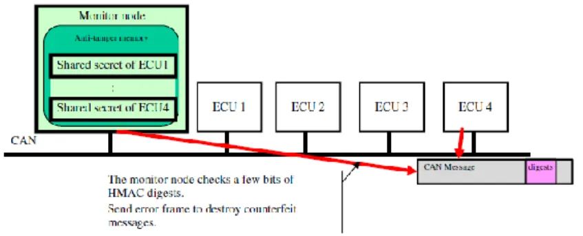
authorization delay to be small enough to allow for the speeds required by the CAN bus. CaCAN, or “Centralized Authentication System in CAN (Controller Area Network)” (Kurachi, et al., 2014, p. 1) is another protocol that is currently under investigation. To secure the CAN bus, the authors propose a monitor node that shares a different cryptographic key with each node on the bus. Then, the bus calculates the proper message authentication code (MAC). If it detects an illicit message, it can overwrite the message using an error frame, as seen in Figure 8. This effectively destroys the message. These MAC codes are transmitted during the data portion of the frame, effectively shortening the amount of data that can be transmitted during a frame. As with many of these protocols, they effectively prevent unauthorized traffic from joining the bus in the form of a new node (Kurachi, et al., 2014).
Figure 8. CaCAN representation. Reprinted from "CaCAN: centralized authentication system in CAN" by R.
Beyond normal security techniques such as new protocols or a modified frame, there are techniques that involve changing the way message identification numbers are defined. Generally, this is predefined, and this will still be true, however, under a new technique, the numbers could be run through a filtering algorithm that uses hash keys to generate a different number and learn from the messages being sent. When the learning algorithm is applied in practice, it can sense between multiple types of attacks. (Groza & Murvay, 2018). This technique would be
implemented in the software level of CAN networks. Similarly, the CAN bus can be outfitted with a connection to a small computer than analyzes CAN messages and uses a neural network to process data and find threats (Min-Joo & Kang, 2016).
This section has looked at a variety of the types of protocols or techniques that can be used to protect the CAN bus from malicious or unauthorized traffic. While many of these solutions take into account current protocols and lead into designs that can support the limited data rates of the CAN bus (Lin & Sangiovanni-Vincentelli, 2012), there is still an aspect of securing the CAN bus that must be explored in more detail. Because the reception of a CAN bus frame is a network defined, consistent thing, it is possible to keep the same frame width and adjust the contents slightly. This will be discussed in the following section.
Securing the CAN Bus
The CAN bus continues to be the de facto standard for automobiles, even as consumers progress into an ever-increasingly interconnected smart world. The two-wire implementation makes it a staple pin of intra-vehicular communications and allows for software definition of much of the load of logical control of a vehicle. It is upon this notion that this paper builds the idea of a new security standard.
CAN Bus Security Vulnerability
While much of the strength of the CAN bus comes in its inherent multicasting ability, this opens the large security vulnerability of any sender on the network being able to send messages of any type. Furthermore, as self-diagnostic applications (discussed in the section General
Security Threats) and other third-party tools allow unauthorized traffic on the CAN bus, not only physical threats can compromise the integrity of the information found in the network. Because of this, a strategy must be examined to determine which nodes are authorized to send messages on a given network. While a solution in this vein does not necessarily address all security issues, it provides a stronger base for the CAN bus to reside in and makes it more difficult for malicious entities to compromise the integrity of the network. The following proposal is designed to meet the goals and should be treated as a framework to be investigated.
Proposed Solution
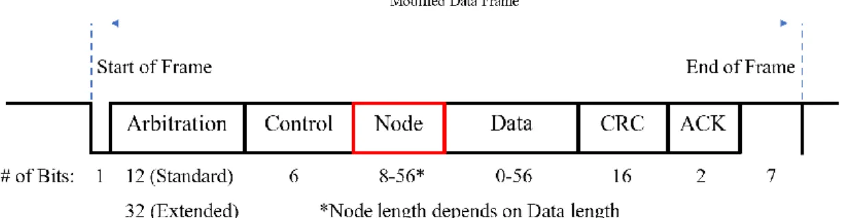
In order to verify nodes, it is possible for a modification to be made to the CAN bus frame. Using even one byte from the overall frame allows 256 different node identifiers to be implanted into a standard CAN frame. Having a node identifier allows for other nodes to verify that the message currently being transmitted is a valid CAN message. Should a node join the network and attempt to transmit a message, other CAN nodes will be able to recognize the lack of an identifier or the presence of an incorrect identifier and throw an error as they would during a different error state. This identifier should be randomly assigned during the initial setup of the CAN bus, as this allows for pre-identification of verified nodes. Figure 9 shows the proposed modification to the CAN bus data frame. The portion in red is the additional field added to the
original specifications for the CAN bus, and its length and definition will be discussed further later in the paper.
Figure 9. Proposed Modification to CAN Data Frame
Software implementation. From a software standpoint, this addition holds considerable merit. Because nodes have knowledge of allowable node identifiers stored in non-volatile memory, they can check whether a message is authorized during normal processing of the data frame. However, a modification on this idea allows for a more secure network. During the software definition of each node on the CAN bus, they are loaded with the message identifiers of the messages relevant to their purpose. While this number could be thousands of messages or more, the number of nodes it can receive CAN data frames from is a significantly lower number. Due to hardware limitations, the number maxes out at 110 nodes (Othman et al., 2006).
Therefore, each node should only store a list of which nodes’ identifiers they can accept
messages from. Should they receive a message identifier that appears to be relevant information, but the node identifier is not recognized, an error frame would be thrown. This protects from unauthorized nodes spoofing messages that may have high criticality and sending them to focal points within the CAN bus.
Field placement. As shown in the section CAN Message Frames, the CAN bus has seven distinct fields. A start of frame bit begins the transmission stage, then the arbitration field allows
the highest priority message to transmit. The control field is used to represent the length of the message, which can be up to eight bytes under the original specifications (Bosch, 2011). This is used by the receivers of the message to determine which bytes to pay attention to as the data field. Because the data field has a modifiable length, it is a natural choice for the removal of some capacity. Using one byte (eight bits) leaves seven-byte messages still able to be sent while simultaneously upholding the current CAN standards for frame size. This allows the proposed system to be usable with previously existing systems with only a software change and without modification to hardware. While one byte is the standard example used in this paper, it is important to note that it is by no means a limit. Because it is a data-link-layer-defined
modification on the original CAN bus specifications, each system can use a separate number of bytes to increase the maximum possible number of node identifiers. The length of this field is easily determined by the maximum number of data bytes allowed in the system. The security provided by this modification increases with each additional bit devoted to the identifier, but no standard number should be set as different networks may have differing portions of their data frame available to put towards this improvement. In the CAN FD specification, up to 64 bytes can be used in the data field (Bosch, 2011). It is up to each network configurator to determine what is best for their network, however security increases with the number of bits devoted to a node identifier.
Discussion on security. This proposal strongly shores up the CAN data frame. It adds the concept of a verified sender, which prohibits pre-existing and new nodes from sending or
requesting data frames from where they are not allowed. This strength is offset somewhat by the relative ease for a computer to cycle through node identifiers until it chances upon a correct
match. This is where it is important for each manufacturer to focus on the general structure of the messages of their system and allow as many bits as possible for the node identifier. For example, Equation 1 shows the difference between one byte (eight bits) and two bytes (sixteen bits) worth of node identifier possibilities. While these are not the longest identifiers, it is difficult to raise the ceiling of how long they are both because it takes away from the data portion of the frame and because it increases the processing time of each node. Therefore, it is up to each network designer to determine how many bits should be allocated for a node identifier.
28 = 256; 216= 65,536 (1)
There are a few notable areas in which this proposition does not directly shore up security. First, if a node should be compromised by a third party, that third party would be able to send normal messages on the CAN bus. However, if they attempted to send new messages that target specific nodes that are outside the normal operation of the node they have compromised, that message would be flagged and overwritten by an Error Frame. Should a node with
considerable reach be jeopardized, it will be able to send messages to important nodes that could still impact the safety of the occupants or their information. Therefore, it is important to note that while this increases security across the board, it is not a comprehensive solution.
Conclusion
The CAN bus has maintained a hold over the automobile industry for decades. While the fact that it is still relevant and useful is telling of its robustness and benefit, it is important that it be adapted to fit with the times. It is impossible to ignore the threat of an ever-increasingly interconnected world and the danger that it poses in the form of physical and non-physical
malicious attacks on vehicular transport. Coupled with the increasingly software-oriented design of cars, there are a growing number of ways to subvert the true intentions of the manufacturers. With solutions such as those proposed in this paper, the CAN bus can be shored up and built to last for the next generation of vehicles.
References
Bosch, R. (2011). CAN FD specification. Gerlingen: Robert Bosch GmbH.
Burns, A., & Davis, R. I. (2013). Mixed criticality on controller area network. 25th Euromicro
Conference on Real-Time Systems (pp. 125-134). Paris, France: IEEE.
Davis, R. I., Burns, A., & Bril, R. J. (2007). Controller area network (CAN) schedulability analysis: Refuted, revisited and revised. Real-Time Systems, 240-272.
Di Natale, M. (2012). Understanding and using the controller area network communication
protocol theory and practice. New York City, New York: Springer.
Farsi, M., Ratcliff, K., & Barbosa, M. (1999). An overview of controller area network.
Computing & Control Engineering Journal, 113-120.
Groza, B., & Murvay, P. (2018). Efficient intrusion detection with bloom filtering in controller area networks. IEEE Transactions on Information Forensics and Security, 14(4), 1037-1051.
Groza, B., & Murvay, S. (2013). Efficient protocols for secure broadcast in controller area networks. Transactions on Industrial Informatics, 9, 2034-2042.
Groza, B., Murvay, S., van Herrewege, A., & Verbauwhede, I. (2012). LiBrA-CAN: A
lightweight broadcast authentication protocol for controller area networks. In J. Pieprzyk, A. R. Sadeghi, & M. Manulis (Eds.) Cryptology and Network Security (pp. 185-200). Darmstadt, Germany: Springer-Verlag Berlin Heidelberg.
Hoppe, T., Kiltz, S., & Dittmann, J. (2008). Security threats to automotive CAN networks: Practical examples and selected short-term countermeasures. In M. D. Harrison, & M.-A.
Sujan (Eds.) Computer Safety, Reliability, and Security (pp. 235-248). Newcastle upon Tyne, England: Springer.
Kang, S., Seong, J., & Lee, M. (2018). Controller area network with flexible data rate transmitter design with low electromagnetic emission. IEEE Transactions on Vehicular Technology, 67(8), 7290-7298.
Kurachi, R., Matsubara, Y., Takada, H., Adachi, N., Miyashita, Y., & Horihata, S. (2014). CaCAN: centralized authentication system in CAN. Embedded Security in Cars (pp. 2-10). Europe: ResearchGate.
Lin, C.-W., & Sangiovanni-Vincentelli, A. (2012). Cyber-security for the controller area network (CAN) communication protocol. 2012 International Conference on Cyber Security (pp. 1-7). Washington D.C.: IEEE.
MJoo, K., & Kang, J.-W. (2016). Intrusion detection system using deep neural network for in-vehicle network security. PLoS One, 1-17.
Othman, H. F., Aji, Y. R., Fakhreddin, F. T., & Al-Ali, A. R. (2006). Controller area networks: Evolution and applications. 2nd International Conference on Information &
Communication Technologies (pp. 3088-3093). Damascus: IEEE.
Oyler, A., & Saiedian, H. (2016). Security in automotive telematics: A survey of threats and risk mitigation strategies to counter the existing and emerging attack vectors. Security and
Communication Networks, 4330–4340.
Perrig, A., Canetti, R., Tygar, J., & Song, D. (2000). Efficient authentication and signing of multicast streams over lossy channels. IEEE Symposium on Security and Privacy, 56-73.
Studnia, I., Nicomette, V., Alata, E., Deswarte, Y., Kaâniche, M., & Laarouchi, Y. (2013). Survey on security threats and protection mechanisms in embedded automotive networks.
43rd Annual IEEE/IFIP Conference on Dependable Systems and Networks Workshop
(pp. 1-12). Budapest: IEEE.
Van Herrewege, A., Singelee, D., & Verbauwhede, A. (2011). CANAuth: A simple, backward compatible broadcast authentication protocol for CAN bus. 9th Embedded Security in
Cars Conference.
Wolf, M., Weimerskirch, A., & Paar, C. (2004). Security in automotive bus systems. Workshop
on Embedded Security in Cars, 1-13.
Woo, S., Jo, H. J., & Lee, D. H. (2015). A practical wireless attack on the connected car and security protocol for in-vehicle CAN. IEEE Transactions on Intelligent Transportation
Appendix A: IEEE Permissions These permissions apply to figures 1 and 2.
In reference to IEEE copyrighted material which is used with permission in this thesis, the IEEE does not endorse any of Liberty University's products or services. Internal or personal use of this material is permitted. If interested in reprinting/republishing IEEE copyrighted material for advertising or promotional purposes or for creating new collective works for resale or redistribution, please go to
http://www.ieee.org/publications_standards/publications/rights/rights_link.html to learn how to obtain a License from RightsLink.
Appendix B: CAN FD Specification Permissions These permissions apply to figure 3.
Appendix C: Springer Permissions These permissions apply to figures 4, 5 and 6.
Appendix D: John Wiley & Sons Permissions These permissions apply to figure 7.
Appendix E: Ryo Kurachi Permissions These permissions apply to figure 8.