Architecture Change Logs
Aakash Ahmad, Pooyan Jamshidi and Claus PahlLero - The Irish Software Engineering Research Center School of Computing, Dublin City University, Ireland
[ahmad.aakash|pooyan.jamshidi|claus.pahl]@computing.dcu.ie
Abstract. Service-based architectures have become commonplace, cre-ating the need to address their systematic maintenance and evolution. We investigate architecture change representation, primarily focusing on the identification of change patterns that support the potential reuse of common changes in architecture-centric evolution for service software. We propose to exploit architecture change logs - capturing traces of se-quential changes - to identify patterns of change that occur over time. The changes in the log are formalised as a typed attributed graph that allows us to apply frequent sub-graph mining approaches to identify po-tentially reusable, usage-determined change patterns. We propose to fos-ter the reuse of routine evolution tasks to allow an architect to follow a systematic, reuse-centered approach to architectural change execution.
Key words: Service-driven Architecture, Change Patterns, Evolution
1 Introduction
Software architecture represents the global system structure for designing, evolv-ing and reasonevolv-ing about the configurations of computational components and their interconnections at higher abstraction levels. Service-Oriented Architecture (SOA) is an architectural approach that models business processes as technical software services. Once deployed, continuous change in business and technical requirements leads towards frequent maintenance and evolution in service sys-tems [12]. In order to accommodate recurring changes in the SOA lifecycle, the solution lies in developing processes, frameworks and patterns that enable change reuse for architectural evolution of service software [12].
We have been working on the ‘Pat-Evol’ project [2, 3] that aims at supporting pattern-driven reuse in architecture-centric evolution for service-driven software. Based on the taxonomy of software change [1], we believe that a systematic in-vestigation of architecture change history could help us to discover sequences of recurring change that occur over time. Recurring changes can be exploited to identify change patterns that support a generic, potentially reusable solution to recurring architecture evolution problems. Therefore, we focus on change representation and its operationalisation by maintaining an architecture change log -tracing each individual change - for our case studies. The change log keeps a
se-quential history (as the ‘post-mortem’ data) of architectural changes, providing us with an empirical foundation to identify patterns of change.
Although a recent emergence of evolution styles [5, 13, 6, 7] promotes the ‘build-once use-often’ philosophy in architecture and process evolution, it falls short of addressing frequent demand-driven process-centric changes [15, 16] that are central to maintenance and evolution of SOAs. This motivates the needs to systematically investigate architecture change representation that goes be-yond frequent addition or removal of individual components and connectors to operationalise recurrent process-based architectural changes.
The proposed solution is based on formalising architectural changes from the logs as a typed attributed graph [8] that provides formal semantics with its node and edge attribution to operationalise architectural changes [9]. We utilise fre-quent sub-graph mining [4] techniques to not only identify the exact instances, but also inexact matches where only central pattern features suffice for identi-fication. The scalability of solution beyond manual analysis is supported with a prototype ‘G-Pride’ (Graph-based Pattern Identification) that facilitates au-tomation and parameterised user intervention for pattern identification process. We believe, a continuous experimental identification of patterns is the first step towards facilitating the architect(s) to capitalise on a reuse-centered approach to systematically accommodate recurring changes in existing software.
This paper is organised as follows. A formal specification for the change pat-tern(s) is presented in Section 2, followed by an overview of the proposed solution in Section 3. We elaborate on graph-based pattern identification in Section 4 and its evaluation in Section 5. In order to justify the overall contribution, related work is presented in Section 6 that is followed by conclusions.
2 Change Pattern
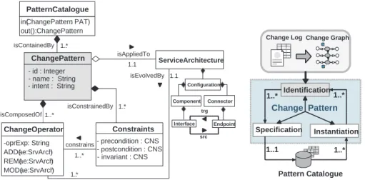
In change logs, we observed that the operationalisation of individual changes rep-resent a parameterised procedural abstraction. This helps us to define change pattern as a generic, first class abstraction (that can be operationalised and pa-rameterised) to support potentially reusable architectural change execution. We present a formal description of change pattern in terms of a meta-model of its constituent elements in Figure 1a along with its properties in Figure 1b. 2.1 Pattern-based Architecture Evolution
We model pattern-based evolutionP atEvol=< SArch, OP R, CN S, P AT >as 4-tuple with element inter-relationships in Figure 1a as explained below.
1. Service Architecture (SArch) refers to the architecture elements to which a pattern can be applied during change execution. We utilise at-tributed typed graphs [8] that provide formal syntax and semantics with its node and edge attribution to model typed instances of architectural el-ements. We use the Graph Modeling Language (.GML) for an XML-based
representation of architectural instances. The architectural model is con-sistent with the Service Component Architecture specifications that include configurations (CFG) among a set service components (CMP) as the compu-tational entities that are linked through connectors (CON), in Figure 1a. The modeling is restricted to service-based architectures that only support com-position or association type dependencies among service composites. Thus, the structural integrity of architecture elements and consistency of pattern-based change beyond this architecture definition is undefined.
- name : String - intent : String 1..* 1..* 1..* 1..1 - precondition : CNS - postcondition : CNS - invariant : CNS -oprExp : String ADD(ae :SrvArch) REM(ae :SrvArch) MOD(ae :SrvArch) in(ChangePattern: PAT) out():ChangePattern isContainedBy 1..* isAppliedTo constrains ServiceArchitecture isEvolvedBy 1..1 1..* isComposedOf isConstrainedBy - id : Integer PatternCatalogue ChangePattern ChangeOperator Constraints Configuration Component Connector Interface Endpoint src trg
a) Structural Model for Pattern-based Evolution b) Fundamental Properties of Change Patterns
Identification Instantiation 1..* 1..* Pattern Catalogue 1..1 1..* Change Log Specification Change Pattern Change Graph
Fig. 1. Model Representation for Reusable Architecture Evolution.
2. Change Operator (OPR) represents operationalisation of changes that is fundamental to architectural evolution. Our analysis of the log goes be-yond basic change types [1] to define a set of atomic and composite oper-ations enabling structural evolution by adding (ADD), removing (REM) and modifying (M OD) the architecture elements (AE). An inherent ben-efit of graph-based modeling is the support for architectural evolution by means of graph transformations. More specifically, during change execution the operations could be abstracted as graph transformation rules (in our case supported by XML transformations using XSLT). This enables a fine-granular operationalisation OP R(ae ∈ AE) to preserve the compositional hierarchy of architecture elements during change execution with:
- Atomic Change Operations: enable fundamental architectural changes in terms of adding, removing or modifying the service operation (OP T), service interface (IN F), connector binding (BIN), connector endpoint (EP T) and configuration interface (cf gIN F).
- Composite Change Operations:are a set of atomic change operations, com-bined to enable composite architectural changes. These enable adding,
re-moving or modifying the components (CM P), connectors (CON) and con-figurations (CF G) with a sequential composition of architectural changes. 3. Constraints (CNS)refer to a set of pattern-specific constraints in terms of
pre-conditions (P RE) and post-conditions (P OST) to ensure consistency of pattern-based changes. In addition, the invariants (IN V) ensure structural integrity of individual architecture elements during change execution. 4. Change Patterns (PAT)represents a recurring, constrained composition
of change operationalisation on architecture elements that is specified as:
P AT<id, name> : P RE(aem ∈ AE)
IN V(OP Rn(aem∈AE))
−−−−−−−−−−−−−−−→ P OST(ae′
m ∈
AE). Constraints enforcement on operational composition ensures structural integrity of architecture elements during pattern-based change execution. Apattern catalogue (CAT)refers to a template-based repository infrastruc-ture to facilitate automated storage (in: once-off specification) and retrieval (out: multiple instantiation) of change patterns during evolution.
2.2 Fundamental Properties of Change Pattern
In addition to the meta-model, the fundamental properties of change pattern are presented in Figure 1b. In order to capitalise on pattern-driven reuse, these properties support our argument about change pattern as a generic solution that can be i) identified as recurrent, ii) specified once and iii) instantiated multiple times to support potentially reusable architectural change execution.
- Identification: aims at an empirical investigation about the history of architec-tural changes to identify recurring sequences of change that occur over time. The motivation for architectural change investigation is to discover and anal-yse real changes (i.e., not any assumed data sets) by extracting the implicit evolution-centric knowledge from change logs, our focus in this paper. - Specification: after identification, it is vital to provide a consistent (once-off)
specification for the collection of identified change patterns as pattern cata-logue. A template-based specification facilitates flexible querying and retrieval whenever a need for pattern usage arises.
- Instantiation: in order to realise the concept of pattern-driven change execu-tion, it allows instantiation of appropriate pattern(s) from its abstract spec-ification to promote the concept of ‘specify-once, instantiate-often’ approach during architecture evolution.
3 Automating Change Pattern Identification
We investigated architectural changes empirically - analysing change represen-tation - to discover recurrent sequences in a change log. Therefore, we have based the identification of patterns on the analysis of changes for two service-based system evolutions we recorded in the log. These include an Electronic
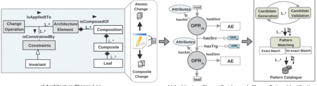
Billing Presentment and Payment (EBPP) system whose specifications are pub-lished by NACHA and an on-line Tour Reservation System (TRS). We propose a three-phase approach to identify architecture change patterns, in Figure 2.
c) Change Pattern Identification a) Architecture Change Log
Architecture Element Constraints isAppliedtTo 1..* isConstrainedBy 1..* isComposedOf 1..* 1..* 1..* Invariant Composite Change Atomic Change
b) Architecture Change Graph Change Operation OPRm AE OPRn AE hasSrc Attributes Attributes OPRm OPRn hasElem hasElem hasAttr hasAttr hasTrg root 1..* 1...* Candidate Validation 1...* Pattern Catalogue Candidate Generation Composite Leaf Composition
Exact Match In-exact Match Pattern Matching
leaf
Fig. 2.An Overview of the Proposed Pattern Identification Process.
3.1 Maintaining the Architecture Change Log
As the initial step, we follow [1] to record the architecture ‘change history’. We use a centrally manageable repository to record sequential architectural changes that are constrained by a set of invariants. We expand on the idea of process change logs from [16] and tailor it to record each individual architectural change as the log tuple. The structural view for the change log is presented in Fig-ure 2a that acts as the foundation to identify change patterns with specific frequency thresholds. While analysing the change operationalisation, each indi-vidual change from the case studies is manually recorded in the log that currently comprises of more than a couple of thousands of changes. (i.e., OP R >2000). The primary benefits of this approach included:
- Maintaining the traces of evolution in an updated central repository.
- Analytical support with searching and querying concrete instances of change. - Experimental analysis of change representation, patterns identification etc.
In Figure 2, the structure of change log maintains the compositional hier-archy of elements. For example, every service component (Composition) must contain at least one or more interfaces (Composite) containing one or more oper-ations (Leaf), while connectors must have binding that contain sn endpoint. We are specifically interested in analysing recurrent sequences that exhibit process-centric changes (e.g. integration, replacement, decomposition etc.) that are cen-tral to SOA evolution, as composite changes based on addition or removal of individual components and connectors.
3.2 Graph-based Formalisation of Architectural Changes
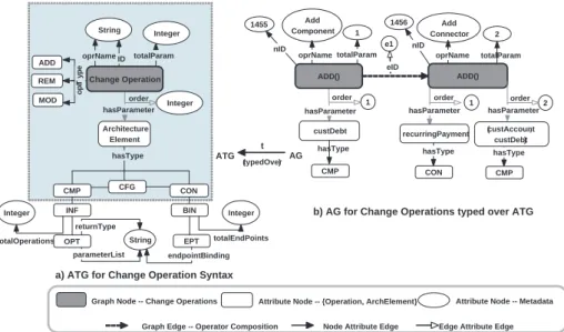
We formalise the architectural changes in the log as an attributed graph (AG) with its nodes and edges typed over an attributed typed graph (ATG) [8] using
an attributed graph morphism t : AG → AT G as indicated in Figure 3. The ATG provides formal semantics to represent atomic and composite changes with visualisation, efficient searching and analysis of sequential changes in the log. However, we are specifically interested in exploiting frequent sub-graph mining to identify recurring sequences as potential change patterns.
Integer Architecture Element Add Component 1 hasParameter Integer order ADD() custDebt totalParam oprName oprName hasParameter hasType Add Connector 2 totalParam oprName 1 hasParameter order CON hasType recurringPayment 2 order CMP hasType (custAccount, custDebt) ADD()
a) ATG for Change Operation Syntax
b) AG for Change Operations typed over ATG
OPT EPT Integer CMP hasType totalOperations Integer totalEndPoints String returnType parameterList endpointBinding INF BIN CMP CFG CON Lifted ATG nID e1 nID 1 order ADD MOD REM o p rT y p e 1455 1456 String Change Operation ID
Graph Edge -- Operator Composition Node Attribute Edge Edge Attribute Edge Attribute Node -- Metadata Graph Node -- Change Operations Attribute Node -- {Operation, ArchElement}
totalParam eID ATG (typedOver) AG t hasParameter
Fig. 3. Attributed Graph to Formalise Architecture Change Operationalisation.
Lifting the Change Graph - Sequential Composition: In the change log, analysing an individual change lacks the required abstraction to exploit the recurrent process-centric changes. Furthermore, taking into consideration the granularity of architectural changes (OP R in Section 2) there does not exist a unified representation for architectural evolution that satisfies the needs for all stake-holders’ view. For example, a software developer might be more interested in analysing the modification of a specific operation’s signature and their se-mantics, while the architect would be exclusively concerned about the affected component-level interconnections. The possible views could be virtually unlim-ited depending on any specific evolutionary perspectives. However, in this paper, instead of focusing on atomic changes we focus on sequential composition iden-tification that exhibits process-centric aspects of change in terms of integration, replacement, decomposition of elements. Therefore, we apply graph lifting [11] to enable projection onto higher-level architectural composites that include con-figurations, components and connectors, hiding low-level atomic changes.
Creating the Change Session Graph: Once the graph is lifted, we provide a utility method assessionGraph(uID, strTime, endTime)to automatically create the change graph based on a particular change session in the log. The
change session is determined by the identification of the user (uID) who applied the change(s) in a specific time interval (endT ime-strT ime). For experimental purposes, we consider all the changes in the log as a single session to extract the attributes of change instances that, we generate the lifted change graph (Figure 3a - dotted blue square) with a concrete represention using the Graph Modeling Language (.GML) format. The result is a directed graph representing sequential composition of change operationalisation, illustrated in Fig. 3b.
For clarity of presentation, some additional attributes (like date, time, com-mitter of change etc.) from the actual graph are hidden to focus on the se-quencing of operations on architecture elements. The attributed graph morphism
t : AG→ AT Gis defined over graph nodes with t(M etaData) = ChangeData
that results int(ChangeOperation) =ADD(),t(ArchitectureElement) =
cust-Debt, recurringPayment, custAccountandt(hasT ype) =CMP, CONin Figure 3.
The change operationalisation as a typed attributed graph is expressed as 5-tuple:GC= < NG, NA, EG, EN A, EEA>, with:
1. Graph Nodes NG = {n(gi)|i = 1, ..., k} is the set of graph nodes. Each
node represents a single change operation (i.e., add a component, remove a connector etc.), where t(NG) =ADD(), REM(), MOD().
2. Attributed NodesNA ={n(ai)|i= 1, ..., l} is the set of attribute nodes.
Attribute nodes are of two types: i) attribute nodes with change metadata, e.g. change operation, name, number of parameters and ii) attribute nodes representing architecture elements (and their compositions) e.g. configura-tion, component, connector etc, where t(NA) =(AE : hasType).
3. Graph EdgesEG={e(gi)|i= 1, ..., k−1}is the set of graph edges which
connect sourcen(g)srcand targetn(g)trgnodes. It represents the sequencing
of change operations in the graph, where t(EG) = eID(NGisrc,NGitrg).
4. Node Attributed Edges EN A ={e(nai)|i = 1, ..., m} is the set of node
attribute edges which join a graph node n(g) to an attribute node n(a), where t(EN A) =nodeAttr(String), e.g.nID, oprName, totalParam.
5. Edge Attributed Edges EEA = {e(eai)|i = 1, ..., n} is the set of edge
attribute edges which join a node attribute edge e(na) to an attribute node n(a), where t(EEA) =edgeAttr(String), e.g.eID, eName.
For example in Fig. 3b, the attributed graph represents two change opera-tions extracted from EBPP architectural changes. It illustrates the addition of a new service component (custDebthasType CMP) that is connected to an exist-ing component (custAccounthasType CMP) with a connector (recurringPayment
hasType CON). The graph nodes are linked to each other using graph edges e(g) having edge id (e1) along with the ids of its source and target nodes (1455, 1456) representing the applied sequence of change operations.
4 Graph-based Identification of Change Patterns
Once architectural changes in the log are formalised as an architecture change graph GC, the final step involves graph-based identification of change patterns.
We exploit one of the classical approaches for pattern mining with sub-graph isomorphism [4] from recurring sub-graphsGP toGC, where GP ⊆GC.
4.1 Properties and Types of Change Sequences
Operationalising the change representation is particularly beneficial to define se-quential composition of change operations on architecture elements. This allows us to abstract the individual changes into a sequence of recurring change oper-ations representing potential patterns determined by the following properties.
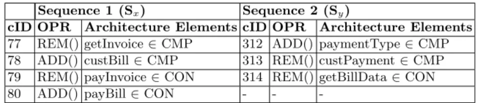
In order to exemplify the properties, Table 1 represents two change sequences (Sx and Sy) extracted from the change log. The sequences contain change id
(cID), change operation (OPR) and the affected architecture element (AE). Note, that for space reasons we do not explicitly represent the parameters for connectors as they are insignificant during sequence matching. Sequence 1 (Sx)
represents the replacement of the existing component getInvoice with custBill
and the corresponding connectorspayInvoice, payBill. Sequence 2 (Sy) represents
the addition of a new componentpaymentTypethat is followed by removal of an existing componentcustPaymentand a connectorgetBillData.
Sequence 1 (Sx) Sequence 2 (Sy)
cID OPR Architecture Elements cID OPR Architecture Elements
77 REM() getInvoice∈CMP 312 ADD() paymentType∈CMP
78 ADD() custBill∈CMP 313 REM() custPayment∈CMP
79 REM() payInvoice∈CON 314 REM() getBillData∈CON
80 ADD() payBill∈CON - -
-Table 1.Change Sequences (Sx andSy) as Extracted from the Change Log
Type Equivalence (TypeEqu) refers to the equivalence of two change operations given by the utility functionT ypeEqu(OP R1(aei:AE), OP R2(aej :
AE)) : returns < boolean >. It depends on the type of change operation and
the architecture element for a change operation to categorised as type equivalent (return true) or type distinct (returns false). For example, the change operation
REM(getInvoice∈CM P) is only equivalent toREM(custP ayment∈CM P)
andTypeEqu(77, 313)returnstrue, as in Table 1.
Length Equivalence (LenEqu)refers to the equivalence of length of two change sequences where length of a change sequence is defined by the number of change operation contained in it. It is given by the function LenEqu(Sx, Sy) :
returns < integer >. Therefore, the length equivalence of two change sequences
SxandSy is determined by the numerical value (0 implesSx==Sy, -n implies
Sx < Sy by n nodes and +n implies Sx > Sy by n nodes). For example, in
Table 1 the length ofSx> Sy by one operation soTypeEqu(Sx, Sy)returns 1.
Order Equivalance (OrdEqu) refers to the equivalence in the order of change operations of two sequences. Analysing the change log based on a given
change session, we observed that it is normal for same user to perform simi-lar changes using different sequencing of change operations. The semantics and impact of change operation remains the same even if sequencing of change operations is varied. It is given by the function OrdEqu(Sx, Sy) : returns <
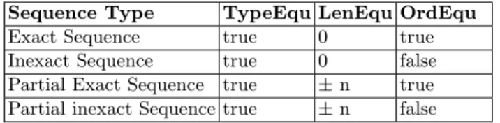
boolean >. We distinguish different types of identified sequences, in Table 2.
Sequence Type TypeEqu LenEqu OrdEqu
Exact Sequence true 0 true
Inexact Sequence true 0 false
Partial Exact Sequence true ±n true
Partial inexact Sequence true ±n false
Table 2.The Types of Identified Sequences in the Change Log.
- Exact Sequence: Two given sequences are exact subsequences if they match on operational types, length equivalence and the ordering of the change opera-tions. In Table 1, Sx and Sy are not the exact sequences because in both the
sequence length and the order of operation do not match.
- Inexact Sequence: Two given sequences are inexact matching sequences if their operational types and lengths are equivalent, but order of change operation varies. In Table 1SxandSy are not the inexact matching sequences asSx> Sy.
- Partial Exact Sequence:Two given sequencesSxandSyare partially exact
such that (if n > 0 than Sy ⊂ Sx, or if n < 0 than Sx ⊂ Sy) - however, the
types and ordering of the change operations in the matched sequences must be equivalent. In Table 1 Sx and Sy are not partial exact matching sequences as
the order of operations in both the sequences do not match.
- Partial Inexact Sequence:Two given sequences Sx and Sy are partial and
inexact if (if n >0 than Sy ⊂Sx, or if n <0 thanSx⊂Sy); in addition, the
operations within both sequences must be type equivalent, while the order of change operations in both sequences varies. In Table 1 Sx and Sy are partial
inexact match. Although Sx > Sy, still Sy ⊂ Sy as cID(77, 78, 79) matches
cID(312, 313, 314) (OrdEqu(Sx, Sy)returnstrue).
4.2 Pattern Identification Process
The properties in Table 2 are vital to not only identify exact instances, but also inexact matches and possible variants of a change pattern where only some pattern features suffice for identification. We introduce the pattern identification problem1as a modular solution. This enables automation along with appropriate user intervention and customisation through parameterisation in Table 3 for pattern identification. We follow an apriori-based approach that proceeds in a generate-and-test manner using a Breadth First Search strategy during each
1 The algorithms along with the developed prototype can be accessed at:
iteration to i) generate and ii) validate pattern candidates fromGC and finally,
(iii) determine the occurrence frequency of exact and inexact candidates inGC.
Parameter Description
GC Change session graph created from change Log.
SC Candidate sequences generated from change graph:SC⊆GC.
GP Identified Pattern instance from change graph:GP ⊆GC.
Len(SC) Candidate length representing number of change operations inSC.
minLen(SC) Minimum candidate length that is specified by the user:
minLen(SC)≤Len(sc) :sc∈SC.
maxLen(SC) Maximum candidate length that is specified by the user:
maxLen(SC)≥ Len(sc) :sc∈SC.
F req(SC) Frequency threshold that is specified by the user forSCto be
iden-tified as a patternGP.
List(param:GC) The list of candidatesSCor patternsGP asparam⊆GC.
Table 3.List of User Specified Parameters for Pattern Identification
Candidate Generation. The initial step of pattern identification generates a set of candidate sequencesSCfrom change graphGC. A candidate consists of a
number of nodes representing change operationalisation on architecture elements as a potential pattern depending on its occurrence frequency F req(SC) inGC.
Input(s)is the change graphGC and user specified minimumminLen(SC) and
maximummaxLen(SC) candidate sequence lengths.Output(s)is a list of
gener-ated candidatesList(SC) such thatminLen(SC)≤Len(SCi)≤maxLen(SC).
Candidate Validation. We observed that during candidate generation, there may exist some false positives in terms of candidates that violate the struc-tural integrity of architecture elements when identified and applied as patterns. Therefore, it is vital to eliminate such candidates through validation for each generated candidate sequence scagainst architectural invariants before pattern matching. Input(s)is a candidatesc∈GC (called from candidateGeneration(),
each time a candidate is generated).Output(s)a boolean value indicating either valid (true) or invalid (false) candidate sequencesc.
Pattern Matching. The last step identifies exact and inexact instances of change patterns based on a user specified frequency threshold. This is achieved by structural matching using sub-graph morphism [4] among the nodes of
List(SC) to corresponding nodes in GC. Input(s) is a list of (validated)
can-didatesvList(SC), specified frequency thresholdF req(SC) andGC.Output(s)
is a list of identified patterns consisting of pattern instanceGP and its frequency
F req(GP). A given candidate is an identified pattern (exact or inexact) if its
5 Experimental Analysis and Illustration
The identified pattern types are generally classified as Inclusion, Exclusion and Replacement types depending on the impact of change as addition, removal or modification of elements from existing architecture.
5.1 Identified Pattern Instance - Component Integration
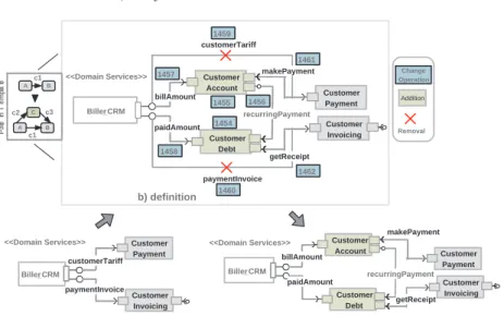
In Table 5, we present an identified instance of the co-related Inclusion pattern that is specified as Integrate (CNS, OPR, AE). Such a declarative specification facilitates the retrieval of appropriate patterns from a catalogue, consisting of the syntactical context that contains pattern pre- and post-conditions (CNS), the applied change operations (OPR) and the affected architecture elements (AE). The co-related Inclusion pattern aims atintegration of mediator services among two or more directly connected service components. The column cID represents the sequences of change as it is captured in the change log and later as individual graph nodes. Figure 4 represents a partial architecture view for the EBPP case study (integrate direct debit to customer accounts and adjust customer debt) captured as a recurring sequence (F req(SC) = 8) in Table 4.
Name = Corelated Inclusion, Id = 3, CLS = 1, Intent =“...”, Frequency = 8 Precondition(s): as in Figure 4a, PostCondition(s): as in Figure 4c
cID OPR Architecture Elements Parameters
1454 ADD() CustomerAccount∈CMP “ ”
1455 ADD() CustomerDebt∈CMP “ ”
1456 ADD() recurringPayment∈CON CustomerAccount, CustomerDebt∈CMP
1457 ADD() billAmount∈CON Biller CRM, CustomerAccount∈CMP
1458 ADD() paidAmount∈CON Biller CRM, CustomerDebt∈CMP
1459 REM() customerTariff∈CON Biller CRM, CustomerPayment∈CMP
1460 REM() paymentInvoice∈CON Biller CRM, CustomerInvoicing∈CMP
1461 ADD() makePayment∈CON CustomerAccount, CustomerPayment∈CMP
1462 ADD() getReceipt∈CON CustomerDebt, CustomerInvoicing∈CMP
Table 4.Template-based Specification of Change Pattern Instance
For example, in Figure 4 the preconditions specify the components (Biller CRM, CustomerPayment, CustomerInvoicing) and connectors (customerTariff, pay-mentInvoice) must exist in the architecture before a pattern can be applied. In addition, the post-conditions specify the addition of new components ( Customer-Account, CustomerDebt) and connectors (makePayment, recurringPayment, ge-tReceipt) as a result of pattern-driven change execution. The change operations specify the execution aspects in terms of addition or removal of specified elements from the architecture, illustrated in Figure 4b.
Customer Account Customer Debt Biller_CRM <<Domain Services>> Customer Payment Customer Invoicing recurringPayment customerTariff paymentInvoice b) definition Biller_CRM Customer Payment <<Domain Services>> Customer Invoicing customerTariff paymentInvoice a) pre-conditions Customer Account Customer Debt Biller_CRM <<Domain Services>> Customer Payment Customer Invoicing makePayment getReceipt c) post-conditions 1454 1455 1456 1457 1458 1459 1460 1461 1462 billAmount paidAmount makePayment getReceipt billAmount paidAmount recurringPayment A B C A B c1 c3 c2 c1 P a tte rn T e m p la te Change Operation Addition Removal
Fig. 4.An Example of the Identified (Co-related Change) Pattern Instance.
5.2 Algorithmic Analysis
Pattern identification from change logs, which can potentially be significant in size, requires an efficient solution. In our trials, we observed that the preprocess-ing for a significant graph size (i.e,GC.size() =OP R≥2278) remains constant
with average complexity time = 888.9 ms. However, such pre-processing is fun-damental to our approach and the benefit for candidate validation lies in elimi-nating the potential patterns (false positives) that may violate the structural in-tegrity of an architecture. We customise the input parameters as:minLen(SC) =
2, maxLen(SC) = 9 with total change operations: GC.size() = 2278. In
addi-tion, we increase the pattern frequency threshold F req(SC) by 2 in each trial,
where T ime ∝ F req(SC) and F req(SC) ∝ 1/Instances. The technical
differ-ence between the exact and inexact pattern matching is detailed in Section 4. The summary of comparison (on average): time (exact : inexact) in milliseconds = T(564:1214) ms and identified patterns instances (exact : inexact) = I(21:38),
forGC.size() = 2278.
Possible Limitations:The proposed approach falls short of capturing dy-namic dependencies in terms of service compositions that correspond to the behavioral aspects in SOAs. These dynamic dependencies go beyond structural graph matching and is out of the scope for this research. The limitation is in-herent in the change log that only captures association type connectors that correspond to structural changes. In addition, change patterns do not necessar-ily support an optimal solution to architecture evolution problem; instead they promote an alternative and potentially reusable solution.
6 Related Work
Two areas patterndriven change reuse and graphbased pattern identification -play a role in our research. The solutions forpattern-based architecture evolution utilise evolution styles [5] and more specifically “evolution shelf” [13] as a generic infrastructure to achieve for-reuse and by-reuse techniques for software architec-ture evolution. It aims at supporting refactoring patterns (i.e., add a component, move a component etc.) that can be composed into further advanced evolution styles (add a client, move a client etc.). In contrast to the evolution styles [5, 13] for more conventional component architectures, we observe that operationalisa-tion of changes in the log exhibits process-centric patterns of change unlike the frequent addition or removal of individual components and connectors.
A catalog of process change patterns [15] can guide change in process-aware information systems. In contrast, we exclusively focus on change operationalisa-tion for architectural abstracoperationalisa-tion. This allows us to argue about change patterns as generic, first class abstraction that can be specified once and instantiated multiples times to support potential reuse in architecture-based change execu-tion. We follow ideas in [16] that utilise process change logs to gain an empirical insight into the context and scope for process instance changes. Our solution focuses on fostering the common architectural changes that could guide the ar-chitects to follow a reuse-centered approach for architectural change execution.
The solution to our pattern identification problem is similar to other graph-based pattern identificationtechniques based on frequent sub-graph mining tech-niques [4]. We use an apriori-based approach with Breadth First Search strategy for iterative graph matching. In this context, Graph X-Ray (G-Ray) [10] works on attributed graphs to find subgraphs that either match the desirable query pattern exactly, or as close as possible based on pre-defined criteria. We are specifically concerned with identifying patterns in medium to large attributed graphs where graph nodes and edges may have multiple attributes that contain instances of architecture elements and pattern-specific constraints.
7 Conclusions
Service software evolves as a consequence of business and technical change cycles. Scalability beyond manual evolution and change support is required to enable a systematic change reuse during architecture evolution. Investigating the history of sequential architectural changes allows post-mortem analysis to identify pat-terns as generic, potentially reusable solution for software architecture evolution. The contribution of this paper is a graph-based formalism for architecture change representation that allows automation along with parameterised customisation to identify change patterns.
In the future, we will focus on developing a pattern catalogue as a repos-itory infrastructure to support an automated storage and retrieval of change patterns. We utilise an XML pattern template that allows for once-off abstract
specification for identified patterns [17] that can be queried and instantiated with concrete pattern instances to support potentially reusable architecture evolution.
References
1. J. Buckley, T. Mens, M. Zenger, A. Rashid, and G. Kniesel. Towards a Taxonomy
of Software Change.Jrnl of Software Maintenance and Evolution, 17:309–332, 2005.
2. A. Ahmad and C. Pahl. Pat-Evol: Pattern-drive Reuse in Architecture-based
Evo-lution for Service Software InERCIM News 88. January 2012
3. A. Ahmad and C. Pahl. Customisable Transformation-Driven Evolution for
Ser-vice Architectures. In Europ. Conf. on Software Maintenance and Reengineering
CSMR’2011. Doct. Consort. 2011.
4. C. Jiang, F. Coenen and M. Zito. A Survey of Frequent Subgraph Mining Algo-rithms. 2004.
5. D. Garlan, J. Barnes, B. Schmerl, and O. Celiku. Evolution Styles: Foundations
and Tool Support for Software Architecture Evolution. InProceedings of the Joint
Working IEEE/IFIP Conference on Software Architecture, 2009.
6. V. Gruhn, C. Pahl, and M. Wever. Data Model Evolution as Basis of Business
Pro-cess Management. In14th International Conference on Object-Oriented and Entity
Relationship Modelling O-O ER95.Springer-Verlag (LNCS Series), 1995.
7. Javed, M., Abgaz, Y.M., Pahl, C.: A pattern-based framework of change operators for ontology evolution. In: On the Move to Meaningful Internet Systems: OTM
Workshops,LNCS, vol. 5872, pp. 544–553. Springer (2009)
8. H. Ehrig, U. Prange and G. Taentzer. Fundamental Theory for Typed Attributed
Graph Transformation. InGraph Transformations, pages 161–177. Springer, 2004.
9. C. Pahl. A Formal Composition and Interaction Model for a Web Component
Plat-form. In ICALP’2002 Workshop on Formal Methods and Component Interaction.
Electronic Notes in Theoretical Computer Science. 2002.
10. H. Tong, C. Faloutsos, B. Gallagher and T. Eliassi-Rad. Fast Best-Effort Pattern
Matching in Large Attributed Graphs. In13th ACM International Conference on
Knowledge Discovery and Data Mining - KDD’07, pages 737–746, 2007.
11. H. Fahmy and R.C. Holt. Using Graph Rewriting to Specify Software Architectural
Transformations. In15th Intl Conf on Automated Software Engineering, 2000.
12. G. Lewis, D.B. Smith, and K. Kontogiannis. A Research Agenda for Service-Oriented Architecture (SOA): Maintenance and Evolution of Service-Service-Oriented Sys-tems. Technical report, Software Engineering Institute, 2010.
13. O. L. Goaer, D. Tamzalit, M. Oussalah and A. D. Seriai. Evolution Shelf: Reusing
Evolution Expertise within Component-Based Software Architectures. In32nd
An-nual IEEE Intl. Computer Software and Applications Conference, 2008.
14. R. Ng, L. Lakshmanan, J. Han and A. Pang. Exploratory Mining and Pruning
Optimizations of Constrained Associations Rules. InSIGMOD’98 Conference, 1998.
15. B. Weber, S. Rinderle, and M. Reichert. Change patterns and change support
features in process-aware information systems. InIntl Conf on Advanced information
systems engineering CAiSE’07. Springer-Verlag, 574-588. 2007.
16. C.W. G¨unther, S. Rinderle-Ma, M. Reichert, W. M.P. van der Aalst. Change
Mining in Adaptive Process Management Systems In14th Intl Conference on
Co-operative Information Systems(CoopIs). LNCS 4275, pp. 309-326, 2006
17. R. Barrett, L. M. Patcas, J. Murphy, and C. Pahl. Model Driven Distribution
Pattern Design for Dynamic Web Service Compositions. InInternational Conference