S
TEEL
-F
IBRE
-R
EINFORCED
-C
ONCRETE
P
AVEMENTS
A thesis submitted for the degree of Doctor of Philosophy
By
Naeimeh Jafarifar
(BSc, MSc)
Department of Civil and Structural Engineering
The University of Sheffield
Sheffield
November, 2012
“To my parents for their everlasting concerns, To my husband, without his supports it couldn’t have been possible to make such a thing,
ACKNOWLEDGEMENTS
I would like to express my deepest gratitude to my supervisor Prof. Kypros Pilakoutas for his continuous support and inspiration. I thank him for his valuable advices, high level of knowledge, and his positive flexibility.
I also would like to appreciate my co-supervisor Dr Terry Bennett for his good collaboration in solving my issues, his valuable advices, and the detailed correction of my thesis.
I acknowledge Ecolanes project, for giving me the chance of working in an important joint group of academic and industrial partners from all over Europe and for its financial support.
I would like to thank the technical staff of the Materials and Structures Laboratory for their high quality help in the experimental phase, especially Chris Todd for his good collaboration, and Kieran Nash for his continuous and accurate care during my experimental measurements.
I appreciate my good friends in the Construction Innovations Group for the happy moments I had with them, and especially I am grateful to Harris Angelakopoulos for his valuable helps.
I thank my parents for their sacrifices and tolerating the distance between us during my studies.
And, last but not least, I specially thank my husband Alireza who stood like a strong column that I could confidently rely on it, and my son Amirreza who suffered for my success but brought loads of happiness to my small family.
ABSTRACT
The use of steel fibres extracted from waste tyres as reinforcement for concrete pavements has been developed at the University of Sheffield. The EU funded EcoLanes Project (Economical and sustainable pavement infrastructure for surface transport) undertook extensive research and developed solutions for Steel-Fibre-Reinforced-Concrete (SFRC) pavements with a particular focus on using recycled steel fibres and roller compacted concrete. The current research project ran alongside the EcoLanes project and aimed at contributing towards the development of design guidelines for pavements reinforced with recycled steel fibres. It was achieved through a study on the restrained shrinkage behaviour of Recycled-Steel-Fibre-Reinforced-Roller-Compacted-Concrete (R-SFR-RCC) pavements, and its consequent effect on the load bearing capacity and fatigue performance of pavements.
The work in this thesis is mainly based on numerical investigations, but experiments were carried out to obtain the material properties (moisture transport, free shrinkage and mechanical). These basic physical properties were extracted from test results, using inverse analysis. The extent of distress induced by drying shrinkage was evaluated using moisture transport analysis coupled with stress analysis. The effect of shrinkage distress on the load bearing capacity of the pavement was investigated in a comparative way with and without shrinkage. Fatigue test results were also used to study the long-term load-bearing capacity.
It was found that the rate of drying and consequent moisture diffusivity in SFRC is higher than for plain concrete and in RCC it is higher than for CC. Moisture diffusivity varies in the range of 0-5 mm2/day for moisture contents lower than 87-92% and then sharply increases to 30 mm2/day for saturated concrete. Free shrinkage is lower for SFRC compared with plain concrete, at early ages. RCC free shrinkage develops at a more uniform rate compared to CC.
For the studied SFR-RCC pavement, surface micro-cracks are formed predominantly due to curling (with opening density of 0.69 mm/m) potentially forming micro-cracks (0.014 mm-0.056 mm width) spaced at 20 mm-60 mm. Cracking at the top surface initiates from the beginning of drying, and stabilises after 180 days. Shrinkage cracking penetrates down to around a quarter of the slab thickness, and the tensile strength at the top surface reduces 50% of the maximum strength; whereas based on the Concrete Society TR34, the strength reduces by 30% at the surface and drops linearly to zero at half depth. The current study found that the stress induced by curling is dominant, compared to that induced by external restraints.
Shrinkage induced cracks was found to reduce the ultimate load bearing capacity and the fatigue capacity of the pavement by up to 50%.
TABLE
OF
CONTENTS
CHAPTER 1 ... 1
1 INTRODUCTION ... 1
1.1AIMS AND OBJECTIVES OF THE STUDY ... 6
1.2RESEARCH METHOD ... 7
1.2.1 Experimental study ... 7
1.2.2 Analytical study ... 9
1.2.2.1 Data processing analysis ... 9
1.2.2.2 Pavement analysis ... 9
1.3LAYOUT OF THE THESIS ... 10
CHAPTER 2 ... 11
2 LITERATURE REVIEW ... 11
2.1RIGID PAVEMENTS ... 11
2.1.1 Conventional concrete (CC) pavements ... 12
2.1.1.1 Jointed Plain Concrete Pavements (JPCP) ... 12
2.1.1.2 Continuously Reinforced Concrete Pavements (CRCP) ... 14
2.1.2 SFRC pavements ... 15
2.1.2.1 Fibre reinforced concrete ... 15
2.1.2.2 Industrially produced steel fibres ... 16
2.1.2.3 Recycled steel fibres from post-consumer tyres ... 16
2.1.2.4 The procedure of extracting steel fibres from post-consumer tyres ... 17
2.1.2.5 Structural use of steel fibres ... 19
2.1.2.6 Use of steel fibres in ground supported slabs ... 20
2.1.3 RCC pavements... 21
2.1.3.1 Elimination or reduction of joints in RCC pavements ... 22
2.2EARLY-AGE AND EARLY-LIFE DISTRESS IN PAVEMENTS ... 23
2.2.1 Shrinkage ... 25
2.2.1.1 Drying shrinkage ... 26
2.2.1.2 Drying shrinkage of SFRC ... 27
2.2.1.3 Drying shrinkage of RCC ... 30
2.2.2 Restraint and distress ... 31
2.2.2.1 External restraints ... 31
2.2.2.2 Internal restraints ... 32
2.3THE EFFECT OF EARLY-AGE DISTRESS ON LONG-TERM PERFORMANCE OF CONCRETE PAVEMENTS ... 33
2.3.1 Mode of failure in JPCPs ... 34
2.4PREVIOUS ATTEMPTS TO STUDY RESTRAINED SHRINKAGE IN CONCRETE PAVEMENTS ... 37
2.4.1 Shrinkage behaviour of JPCPs ... 37
2.4.2 Shrinkage behaviour of CRCPs... 39
2.4.3 Shrinkage behaviour of SFRC pavements and overlays ... 40
2.4.3.1 SFRC pavements ... 40
2.4.3.2 SFRC overlays ... 40
2.4.4 Shrinkage behaviour of RCC pavements ... 42
2.5DISCUSSION AND CONCLUSION ... 42
CHAPTER 3 ... 45
3 MOISTURE TRANSPORT MECHANISM AND DRYING SHRINKAGE PROPERTIES IN CONCRETE ... 45
3.1 FACTORS INVOLVED IN MOISTURE TRANSPORT AND DRYING SHRINKAGE OF CONCRETE ... 46
3.1.1 Diffusion coefficient ... 46
3.1.2 Convective moisture transfer coefficient, f ... 48
3.1.3 The relationship between free shrinkage strain and moisture loss (“Hygral contraction coefficient”) ... 49
3.2 MOISTURE MEASUREMENT IN CONCRETE ... 49
3.2.1 Modifying the gravimetric method for moisture measurement ... 50
3.2.2 Calculation of moisture content in the gravimetric method ... 52
CHAPTER 4 ... 53
4 EXPERIMENTAL STUDIES ... 53
4.1 MIX PROPORTIONS AND CASTING PREPARATIONS ... 54
4.2 EXPERIMENTAL STUDIES TO OBTAIN MECHANICAL PROPERTIES ... 58
4.2.1 Compressive strength and compressive elastic modulus ... 58
4.2.1.1 Cubes ... 58
4.2.1.2 Cylinders... 59
4.2.1.3 Discussion on compressive test results ... 60
4.2.2 Flexural behaviour, and bending elastic modulus ... 61
4.2.2.1 Prisms for bending tests ... 63
4.2.2.2 Estimation of the bending elastic modulus ... 67
4.2.2.3 Bending test results ... 68
4.2.2.4 Discussion on the bending test results ... 69
4.3 EXPERIMENTAL STUDIES TO OBTAIN MOISTURE MOVEMENT AND SHRINKAGE PROPERTIES ... 74
4.3.1 Specimens for moisture measurement ... 74
4.3.2 Free shrinkage specimens ... 76
4.3.3 Results and discussion on experimental moisture movement and shrinakge properties ... 77
5.1MOISTURE DIFFUSIVITY AND SURFACE FACTOR ... 81
5.1.1 Verifying the FE model for moisture transport analysis ... 83
5.1.2 Inverse analysis for moisture diffusivity and surface factor ... 84
5.2HYGRAL CONTRACTION COEFFICIENT ... 88
5.2.1 Inverse analysis to obtain hygral contraction coefficient ... 89
5.3TENSION STIFFENING PROPERTIES OF SFRC(σ-ε MODELS) ... 95
5.3.1 FE modelling of the flexural SFRC prisms ... 97
5.3.1.1 Element choice for FE modelling of prisms ... 98
5.3.1.2 Comparing alternative material models ... 99
5.3.1.3 Vaerifying the FE model for the flexural inverse analysis ... 101
5.3.2 Inverse analysis of tested prisms and results ... 105
5.3.3 Discussion on the inverse analysis of prisms ... 111
CHAPTER 6 ... 113
6 PAVEMENT ANALYSIS UNDER RESTRAINED SHRINKAGE AND MONOTONIC LOADING ... 113
6.1SIMULATION OF SFRC ROAD PAVEMENTS (APPLIED APPROACHES AND ASSUMPTIONS) ... 114
6.1.1 Modelling approaches for FE analysis of pavements ... 115
6.1.2 Assumptions of modelling ... 116
6.1.2.1 Design load and service life ... 116
6.1.2.2 Geometry of the pavement ... 117
6.1.3 Modelling of the Foundation ... 119
6.1.3.1 Stiffness and strength of the supporting layers... 119
6.1.3.2 Interaction between the slab and the foundation ... 122
6.1.3.3 Loss of support ... 124
6.1.4 Drying creep ... 124
6.1.5 Maturity ... 126
6.1.6 Failure criteria and load bearing capacity ... 128
6.1.6.1 Failure based on the collapse condition ... 129
6.1.6.2 Failure based on cracking criteria ... 130
6.2MOISTURE TRANSPORT ANALYSIS OF SFRC PAVEMENTS... 131
6.2.1 Boundary and initial conditions ... 131
6.2.2 Element type for moisture transport FE analysis of pavements ... 132
6.2.3 Results of the moisture transport analysis ... 133
6.3STRESS ANALYSIS OF SFRC PAVEMENTS AT EARLY AGE ... 134
6.3.1 Element type for FE stress analysis of pavements ... 135
6.3.2 Shrinkage of the SFRC pavement at early-age ... 136
6.3.2.1 SFR-RCC mix, Condition 1: no cohesion between slab and base ... 136
6.3.3 Comparing the FE results with the evaluations given in Concrete SocietyTR34 ... 145
6.3.4 Shrinkage of hardened SFR-RCC pavement ... 149
6.4STRESS ANALYSIS OF SFRC PAVEMENTS UNDER MONOTONIC LOADING ... 150
6.4.1 Monotonic loading only ... 150
6.4.1.1 Corner loading ... 151
6.4.1.2 Longitudinal edge loading ... 153
6.4.1.3 Transversal edge loading ... 156
6.4.1.4 Interior loading ... 157
6.4.2 Monotonic loading with restrained shrinkage ... 158
6.4.2.1 Corner loading ... 158
6.4.2.2 Longitudinal edge loading ... 161
6.4.2.3 Transversal edge loading ... 163
6.4.2.4 Interior loading ... 166
6.4.3 Summary of the results ... 168
6.4.4 Verifying and discussing the results ... 169
6.4.4.1 Existing methods ... 170
6.4.4.2 Verifying the results of the FE model in the elastic range ... 171
6.4.4.3 Verifying the results of the FE model in the ultimate limit state ... 172
6.4.4.4 Discusion of results ... 175
CHAPTER 7 ... 177
7 LONG-TERM FATIGUE ANALYSIS ... 177
7.1EXPERIMENTAL APPROACHES ... 177
7.1.1 Traditional methods to obtain the fatigue endurance curves for concrete pavements ... 177 7.1.1.1 Concrete beam fatigue equations ... 177
7.1.1.2 Field-calibrated fatigue equations for concrete slabs ... 178
7.1.1.3 Laboratory fatigue equations for concrete slabs ... 179
7.1.2 Evolution of damage due to fatigue ... 182
7.2EXPERIMENTAL TEST RESULTS FOR EVALUATION OF FATIGUE PARAMETERS FOR SFR-RCC ... 184
7.3INVESTIGATING THE EFFECT OF SHRINKAGE DISTRESS ON FATIGUE PERFORMANCE... 187
7.3.1 Using the experimental fatigue endurance curve ... 187
7.3.1.1 Number of load cycles at edges and corners ... 187
7.3.1.2 Provided safety factors ... 188
7.3.1.3 Allowable stress ratios ... 189
7.3.2 Using the experimental fatigue damage evolution ... 190
7.4CONCLUSION ... 193
CHAPTER 8 ... 195
8.1.1 Moisture transport mechanism and drying shrinkage properties (Chapter 3) ... 196
8.1.2 Experimental studies (Chapter 4) ... 196
8.1.3 Data processing analysis (Chapter 5) ... 198
8.1.4 Pavement analysis under restrained shrinkage and monotonic loading (Chapter 6) ... 199
8.1.5 Long-term fatigue analysis (Chapter 7) ... 202
8.2LIMITATIONS OF THE CURRENT RESEARCH AND SUGGESTIONS FOR DEVELOPMENT OF THE WORK IN THE FUTURE ... 203
8.2.1 On the research approach ... 203
8.2.2 On the assumptions ... 204
8.2.3 Suggestions for development of design guidelines ... 205
REFERENCES ... 207 APPENDIXES ...
APPENDIX A:ANALYTICAL SOLUTION FOR 1D MOISTURE DIFFUSIVITY EQUATION ... A1-A3 APPENDIX B:DERIVATION OF EQUATION FOR MOISTURE CONTENT IN THE GRAVIMETRIC METHOD . B1-B2
APPENDIX C:EXPERIMENTAL TEST RESULTS ... C1-C19 APPENDIX D:NUMERICAL REPETITIVE SECTION ANALYSIS ... D1-D3 APPENDIX E:CONSTITUTIVE MATERIAL MODELS USED IN FE ANALYSIS ... E1-E10 APPENDIX F:MESH SENSITIVITY ISSUE IN THE SMEARED CRACKING MODEL ... F1 APPENDIX G:FE ANALYSIS INPUT FILES ... G1-G34
LIST
OF
FIGURES
Figure 1.1 - (a) Flexible pavement; (b) Rigid pavement ... 1
Figure 1.2 - Concrete road pavements ... 2
Figure 1.3 - (a) Placing RCC; (b) Compacting RCC ... 3
Figure 1.4 - Placing CC for reinforced concrete pavements ... 3
Figure 1.5 - Diagram of the research outline and the main expected output results ... 8
Figure 1.6 - Layout of the thesis ... 10
Figure 2.1 - Stress distribution (a) Flexible pavement; (b) Rigid pavement ... 11
Figure 2.2 - Brittle cracking, plain concrete ... 12
Figure 2.3 - Longitudinal and transversal joints ... 13
Figure 2.4 - Dowel bars in a crack control joint ... 13
Figure 2.5 - Reinforcement for a CRCPs ... 14
Figure 2.6 - Distributed cracking in reinforced concrete pavements ... 15
Figure 2.7 - Industrial steel fibres; (a) straight; (b) crimped; (c) crimped-end; (d) coned-end ... 16
Figure 2.8 - Recycled steel fibres from post-consumer tyres ... 17
Figure 2.9 - Mechanical treatment to extract recycled steel fibres (a) Tyre granulator (Musacchi et al., 2007); (b) Shredded tyres; (c) Collected granulated rubbers; (d) Collected steel fibres ... 18
Figure 2.10 - Fibre balling in concrete ... 19
Figure 2.11 - Flexural characteristics of SFRC (ACI 544.4R, 1999) ... 20
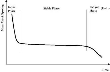
Figure 2.12 - Conceptual reduction in mean crack spacing over time for CRCPs (McCullough et al., 2000 cited in Ruiz et al., 2005b) ... 24
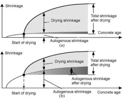
Figure 2.13 - Shrinkage strain components in (a) normal; and (b) high strength concrete (Sakata et al., 2004 cited in Gribniak et al., 2008) ... 26
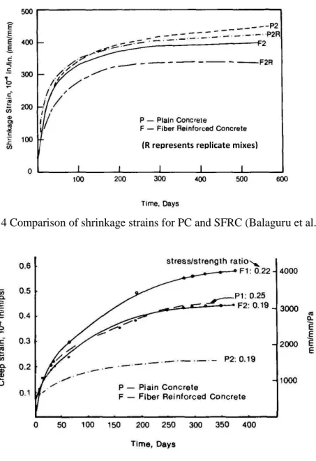
Figure 2.14 - Comparison of shrinkage strains for PC and SFRC (Balagura et al., 1988)... 28
Figure 2.15 - Comparison of creep strains PC and SFRC (Balagura et al., 1988) ... 28
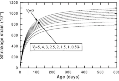
Figure 2.16 - Influence of fibre content on free shrinkage behaviour (Zhang et al., 2001b) ... 29
Figure 2.17 - Initiation and propagation of cracks at the bottom face as the result of external restraint against slippage ... 31
Figure 2.18 - (a) Curling upward; (b) Curling downward ... 32
Figure 2.19 - Initiation of cracks at the top face as the result of internal restraint against curling ... 33
Figure 2.20 - Schematic of long-term performance of JPCPs versus time (Smith et al. 1990) ... 34
Figure 2.21 - Schematic of top-down corner cracking in pavements with upward curling as the result of loss of support and wheel loading (Ruiz et al., 2005b) ... 35
Figure 2.22 - Photograph of corner breaks (Ruiz et al., 2005b) ... 35
Figure 2.23 - Plan view of a corner break (Ruiz et al., 2005b) ... 36
Figure 2.24 - Cracking and edge lifting of a bonded overlay due to shrinkage (Carlswärd, 2006) ... 40
Figure 2.25 - (a) Free shrinkage test proposed by Carlswärd; (b) The principle response on the top and bottom faces due to one-sided drying (Carlswärd, 2006) ... 41
Figure 3.3 - Sealing specimens in the modified gravimetric method ... 51
Figure 3.4 - a) Specimen i in formulation of the moisture content; (b) Full height Concrete element in formulation of the moisture content ... 52
Figure 4.1 (a) Coarse aggregates for CC mixes (river aggregates); (b) Fine aggregate for CC mixes (sand); (c) Blended crushed graded aggregates for RCC mixes ... 54
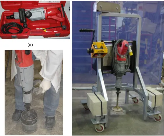
Figure 4.2 (a) Electric vibrating hammer to compact RCC; (b) Operating the hammer manually; (c) Operating the hammer using the metal frame ... 55
Figure 4.3 Statistical length distribution of steel tyre-cord steel fibres used in SFRC mixes... 56
Figure 4.4 Pressure gauge method apparatus ... 57
Figure 4.5 Slump test apparatus ... 58
Figure 4.6 (a) Steel moulds for cube specimens; (b) Cube specimen after crushing ... 59
Figure 4.7 (a) Steel moulds for casting cylinder; (b) Compressive test of concrete cylinder ... 59
Figure 4.8 Mean compressive stress-strain curves ... 60
Figure 4.9 Comparison of compressive strength from cube and cylinders ... 61
Figure 4.10 (a) Steel-plate prismatic moulds; (b) Casting RCC prisms using electric hammer ... 63
Figure 4.11 Notching prisms using rotating diamond blade ... 64
Figure 4.12 (a) Set up of bending test; (b) Arrangement of LVDTs for the notched prisms ... 65
Figure 4.13 (a) Set up of bending test; (b) Arrangement of LVDTs for the un-notched prisms ... 66
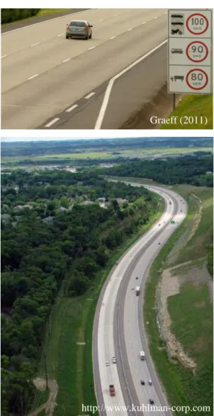
Figure 4.14 Load spreading effect (Graeff, 2011) ... 67
Figure 4.15 Averaged load-deflection curves for various mixes of notched and un-notched prisms ... 68
Figure 4.16 Definition of FL (after BS EN 14651, 2005) ... 70
Figure 4.17 Load-deflection diagram and Fj (j = 1, 2, 3, 4) ... 70
Figure 4.18 Experimental load levels, (a) notched prisms; (b) un-notched prisms ... 71
Figure 4.19 Comparison of the bending modulus of elasticity ... 73
Figure 4.20 Specimens used for moisture measurement ... 74
Figure 4.21 Cutting depths in moisture measurement ... 75
Figure 4.22 Penetration depth of drying after one week drying in the oven in addition to 90 days drying in the experimental conditions, for a broken CC specimen ... 76
Figure 4.23 Prismatic specimen for free shrinkage measurement ... 76
Figure 4.24 (a) Free shrinkage specimens; (b) Free shrinkage measurement device ... 77
Figure 4.25 Experimental moisture profiles, all mixes... 78
Figure 4.26 Strain history curves for free shrinkage specimens ... 79
Figure 5.1 Asad’s (1995): (a) The physical model; (b) 2-D FE simplification of the physical model; (c) 1-D FE discretisation of the physical model ... 83
Figure 5.2 3D FE model of Asad’s sample in the current study ... 84
Figure 5.3 Moisture transport FE analysis in the current research and in the literature ... 84
Figure 5.4 FE model for moisture diffusivity analysis ... 85
Figure 5.5 Moisture diffusivity, ( ), versus moisture content, ... 85
RCC mix; (c) SFR-CC mix (2.5%); (d) SFR-RCC mix (2.5%) ... 87
Figure 5.8 Stress distribution through the section of specimens in the free shrinkage test ... 88
Figure 5.9 FE model for free shrinkage prisms ... 90
Figure 5.10 “Hygral contraction coefficients” versus moisture content ... 92
Figure 5.11 Numerical free shrinkage strain curve compared to the experimental: (a) Plain CC mix; (b) Plain RCC mix; (c) SFR-CC mix (2.5%); (c) SFR-RCC mix (2.5%) ... 93
Figure 5.12 Effect of considering upper limit for βc (C) for plain CC mix; (a) Limits, (b) Free shrinkage time histories ... 94
Figure 5.13 Tensile wave, moving from the surface inward ... 95
Figure 5.14 Multi-linear approximation; (a) tension softening; (b) load-displacement curves ... 96
Figure 5.15 Four-point loaded prism (a) Physical model (b) FE model ... 99
Figure 5.16 Virtual stiffening in the multiple-fixed cracking formulation in CSC models ... 100
Figure 5.17 σ-ε curves for various concrete mixes (Angelakopoulos et al., 2008a,b) ... 101
Figure 5.18 Load-displacement curves for the RCC mix + 2% industrial fibres ... 102
Figure 5.19 Load-tensile strain curves for the RCC mix + 2% industrial fibres ... 102
Figure 5.20 Load-displacement curves for the RCC mix + 3% recycled fibres ... 103
Figure 5.21 Load-tensile strain curves for the RCC mix + 3% recycled fibres ... 103
Figure 5.22 FE models with (a) coarse, (b) medium and (c) fine meshes ... 103
Figure 5.23 Load-displacement curves for the CC mix + 2% industrial fibres ... 104
Figure 5.24 Load-tensile strain curves for the CC mix + 2% industrial fibres ... 104
Figure 5.25 The effect of reinforcement on crack distribution in bending prisms ... 105
Figure 5.26 Tension stiffening curves obtained for the experimetal concrete mixes ... 106
Figure 5.27 Load-deflections for the un-notched prisms, CC mix + 2.5% recycled fibres, CSC model ... 107
Figure 5.28 Load-deflections for the un-notched prisms, CC mix + 2.5% recycled fibres, CDP model ... 107
Figure 5.29 Load-deflections for the notched prisms, CC mix +2.5% recycled fibres ... 107
Figure 5.30 Load-deflections for the un-notched prisms, RCC mix +2.5% recycled fibres, CSC model ... 108
Figure 5.31 Load-deflections for the un-notched prisms, RCC mix +2.5% recycled fibres, CDP model ... 108
Figure 5.32 Load-deflections for the notched prisms, RCC mix +2.5% recycled fibres ... 108
Figure 5.33 Load-deflections for the un-notched prisms, plain CC mix, CSC model ... 109
Figure 5.34 Load-deflections for the un-notched prisms, plain CC mix, CDP model ... 109
Figure 5.35 Load-deflections for the notched prisms, plain CC mix ... 109
Figure 5.36 Load-deflections for the un-notched prisms, plain RCC mix, CSC model ... 110
Figure 5.37 Load-deflections for the un-notched prisms, plain RCC mix, CDP model ... 110
2004a) ... 115
Figure 6.2 (a) The cross section of the dual tyre at one end of a loaded axle; (b) The footprint of the dual tyre; (c) The track width of the commercial vehicle ... 117
Figure 6.3 Continuity of the pavement in modelling ... 118
Figure 6.4 Layers constituting the foundation ... 119
Figure 6.5 Dense liquid and elastic solid extremes of the elastic soil response ... 120
Figure 6.6 (a) Modelling of the foundation layers; (b) Capability of relative movement between the slab and the foundation ... 121
Figure 6.7 Tensile strength development for SFR-RCC mix ... 127
Figure 6.8 Idealised model slab response (Bischoff et al., 2003) ... 129
Figure 6.9 Mesh sensitivity analysis through the thickness (SFR-RRC mix) ... 133
Figure 6.10 Time history of the moisture profiles ... 133
Figure 6.11 Moisture content contour after 1 year drying; (a) SFR-RCC mix; (b) SFR-CC mix ... 134
Figure 6.12 FE model developed for stress analysis of the SFRC pavement ... 135
Figure 6.13 Deformed shape of SFR-RCC pavement, due to drying shrinkage (values in mm) ... 136
Figure 6.14 Time history of (a) maximum cracking strains; (b) maximum tensile stresses, for SFR-RCC pavement and various element sizes... 137
Figure 6.15 Maximum principal component of inelastic (cracking) strains, IEmax, for SFR-RCC pavement, under drying shrinkage; (a) strain contour; (b) strain orientations ... 138
Figure 6.16 Shrinkage cracks (CORD, 1992)... 139
Figure 6.17 Cracking pattern for SFR-RCC pavement, under drying shrinkage ... 139
Figure 6.18 Cracking strains contour in depth, for SFR-RCC pavement, under drying shrinkage ... 140
Figure 6.19 Time history of maximum cracking strain at various depths ... 140
Figure 6.20 Time history of maximum tensile stress at various depths... 141
Figure 6.21 Comparison between the magnitude of the elastic and inelastic strains ... 142
Figure 6.22 Crack development due to drying shrinkage; (a) primary cracks; (b) secondary cracks; (c) tertiary cracks ... 143
Figure 6.23 Deformed shape of fully bonded SFR-RCC pavement, due to drying shrinkage ... 143
Figure 6.24 Maximum principal inelastic (cracking) strains, IEmax, for fully bonded SFR-RCC pavement, under drying shrinkage; (a) strain contour; (b) strain orientations ... 144
Figure 6.25 Maximum inelastic (cracking) strains, IE, for SFR-RCC compared with SFR-CC ... 145
Figure 6.26 Residual tensile strength of the SFR-RCC slab after the effect of drying shrinkage, normalised to the cracking strength ... 146
Figure 6.27 Stress block in calculation of negative moment capacity based on TR34 (a) without shrinkage; (b) reducing shrinkage stress based on TR34; (c) reducing shrinkage stress based on FE analysis ... 148
Figure 6.28 Time history of stress development in the case of a hardened SFR-RCC slab, in comparison with an immature slab ... 149
Figure 6.31 Maximum cracking strain under a total axle load = 8SAL (Corner load only; one end of the axle located at the corner) ... 152 Figure 6.32 Maximum cracking strain at the top surface versus the distance from the corner (Corner load only) ... 153 Figure 6.33 Variation of the equivalent crack opening versus the load (Corner load only) ... 153 Figure 6.34 Cracking strain versus the axle load (Longitudinal edge load only) ... 154 Figure 6.35 Maximum cracking strain under a total axle load =15SAL (Longitudinal edge load only; one end of the axle located at the edge) ... 154 Figure 6.36 Maximum cracking strain at the top surface versus the distance from the edge (Longitudinal edge load only) ... 155 Figure 6.37 Variation of the equivalent crack opening versus the load (Longitudinal edge load only) 155 Figure 6.38 Cracking strain versus the axle load (Transversal edge load only) ... 156 Figure 6.39 Maximum cracking strain under an axle load =12SAL (Transversal edge load only) ... 156 Figure 6.40 Maximum cracking strain at the top surface versus the distance from the transversal edge (Transversal edge load only) ... 157 Figure 6.41 Variation of the equivalent crack opening versus the axle load (Transversal edge load only) ... 157 Figure 6.42 Cracking strain versus the axle load (Interior load only) ... 158 Figure 6.43 Cracking strain versus the axle load (Corner load + Drying shrinkage) ... 159 Figure 6.44 Maximum cracking strains under an axle load = 4SAL (Corner load + Drying shrinkage; one end of the axle located at the corner) ... 159 Figure 6.45 Maximum cracking strain at the top surface versus the distance from the corner (Corner load + Drying shrinkage) ... 160 Figure 6.46 Variation of the equivalent crack opening versus the axle load (Corner load + Drying shrinkage; compared to Corner load only) ... 161 Figure 6.47 Cracking strain versus the axle load (Longitudinal edge load + Drying shrinkage) ... 161 Figure 6.48 Maximum cracking strains at an axle load =7.7SAL (Longitudinal edge load + Drying shrinkage; one end of the axle located at the edge) - plan view ... 162 Figure 6.49 Maximum cracking strain at the top surface versus the distance from the edge (Longitudinal edge load + Drying shrinkage) ... 162 Figure 6.50 Variation of the equivalent crack opening versus the axle load (Longitudinal edge load + Drying shrinkage; compared to Longitudinal edge load only) ... 163 Figure 6.51 Cracking strain versus the axle load (Transversal edge load + Drying shrinkage) ... 164 Figure 6.52 Maximum cracking strains at an axle load = 6.5SAL (Transversal edge load + Drying shrinkage) ... 164 Figure 6.53 Maximum cracking strain at the top surface versus the distance from the edge (Transversal edge load + Drying shrinkage) ... 165 Figure 6.54 Variation of the equivalent crack opening versus the axle load (Transversal edge load + Drying shrinkage; compared to Transversal edge load only) ... 166
Figure 6.56 Maximum cracking strains at an axle load =18.8SAL (Interior load + Drying shrinkage)167 Figure 6.57 Maximum cracking strain at the top surface versus the distance from the axle load (Interior
load + Drying shrinkage) ... 167
Figure 6.58 Variation of the equivalent crack opening versus the axle load (Interior load + Drying shrinkage; compared to Interior load only) ... 168
Figure 6.59 Model of the pavement considered in the Westergaard’s theory ... 170
Figure 6.60 Comparison of FE results and Westergaard’s analytical equations ... 172
Figure 6.61 Interior dual load ... 173
Figure 7.1 Comparison of Rollings’s field-calibrated fatigue curves with Darter’s beam fatigue curve (Roesler et al., 2005) ... 179
Figure 7.2 Comparison of Roesler’s (2005 and 1998) slab fatigue curves based on beam-rupture-modulus, MORbeam, with the beam fatigue curve (Roesler et al., 2005) ... 180
Figure 7.3 Comparison of Roesler’s (2005 and 1998) slab fatigue curves based on slab-rupture-modulus, MORslab, with the beam fatigue curve (Roesler et al., 2005) ... 181
Figure 7.4 Damage evolution (Molinas-Vega et al., 1995) ... 183
Figure 7.5 A semi-empirical damage evolution curve for s=0.8 (Molinas-Vega et al., 1995) ... 183
Figure 7.6 Pattern for variation of mid-span displacement versus the number of cycles, for beam fatigue tests (Graeff, 2011) ... 184
Figure 7.7 Experimental fatigue test results for SFR-RCC (containing 2% recycled fibres), endurance curve (Graeff, 2011) ... 185
Figure 7.8 Experimental fatigue test results for SFR-RCC (containing 2% recycled fibres), mid-span deflection versus the number of load cycles (Graeff, 2011) ... 185
Figure 7.9 The average experimental curve for mid-span deflection versus the number of load cycles, for SFR-RCC (containing 2% recycled fibres)... 186
Figure 7.10 Fatigue damage factor for SFR-RCC (containing 2% recycled fibres), calculated from experimental results ... 186
Figure 7.11 Comparison of N-S curves when shrinkage distress is considered or ignored ... 190
Figure 7.12 Crack initiation versus N/Nf, when shrinkage is ignored and a load factor 4.0 is applied 192 Figure 7.13 Crack propagation versus N/Nf, when shrinkage is considered and a load factor 2.0 is applied ... 192
LIST
OF
TABLES
Table 4.1 Proportions used for CC mixes ... 56
Table 4.2 Proportions used for RCC mixes ... 56
Table 4.3 Gradation of aggregates used for CC and RCC mixes ... 57
Table 4.4 Mean 28-days compressive strength (Cubes) ... 59
Table 4.5 Mean compressive strength and elastic modulus (Cylinders) ... 60
Table 4.6 Elastic modulus obtained from bending tests ... 69
Table 4.7 Values for the LOP, , and residual flexural tensile strengths, ... 72
Table 5.1 Surface factors back-calculated by FE analysis ... 86
Table 5.2 Back-calculated constant parameters, a and b ... 91
Table 5.3 Required parameters to be adopted in CSC and CDP models ... 98
Table 6.1 Alternatives for mesh refinement in moisture transport FE analysis ... 132
Table 6.2 Alternatives for mesh refinement in FE stress analysis ... 135
Table 6.3 Load bearing capacities for various load cases and failure criteria ... 169
Table 6.4 Load bearing capacity of the SFR-RCC Pavement (comparison with TR34)... 175
Table 7.1 Provided safety factors in the long-term ... 188
LIST
OF
ABBREVIATIONS
AND
SYMBOLS
A
BBREVIATIONS1D one dimensional 2D two dimensional 3D three dimensional
AASHTO American Association of State Highway and Transportation Officials ACI American Concrete Institute
ACPA American Concrete Pavement Association ASTM American Society for Testing and Materials BS British Standard
CBR California Bearing Ratio CC Conventional Concrete CDP Concrete Damage Plasticity
CMOD Crack Mouth Opening Displacement CORD Catalogue Of Road Defects
CRCP Continuously Reinforced Concrete Pavement CSC Concrete Smeared Cracking
FAA Federal Aviation Administration FE Finite Element
FEA Finite Element Analysis
FHWA Federal Highway Administration ESAL Equivalent Standard Axle Load HGV Heavy Goods Vehicle
I-SFRC Industrial Steel-Fibre-Reinforced-Concrete ISO Internationnal Standarization Organization JCI Japaneses Concrete Institute
JPCP Jointed Plain Concrete Pavement JRCP Jointed Reinforced Concrete Pavement JSCE Japan Society of Civil Engineers LOP Limit Of Proportionality
LVDT Linear Variable Differential Transformer
NCHRP National Cooperative Highway Research Program PC Plain Concrete
PCA Portland Cement Association PCP Plain Concrete Pavement RCC Roller Compacted Concrete R&D Research & Development
Construction et Ouvrages (International Union of Laboratories and Experts in Construction Materials, Systems, and Structures)
R-SFRC Recycled Steel-Fibre-Reinforced-Concrete
R-SFR-CC Recycled Steel-Fibre-Reinforced Conventional-Concrete R-SFR-RCC Recycled Steel-Fibre-Reinforced Roller-Compacted-Concrete SAL Standard Axle Load
SFRC Steel-Fibre-Reinforced-Concrete
SFR-CC Steel-Fibre-Reinforced Conventional-Concrete SFR-RCC Steel-Fibre-Reinforced Roller-Compacted-Concrete UFC Unified Facilities Criteria
UoS University of Sheffield USFD Unoversity of Sheffield
S
YMBOLSequivalent contact radius of the load
distance from the load centre to the corner of the slab
( ) hygral contraction coefficient
( ) coefficient depending on the age of the concrete width of the test specimen (prisms)
C moisture content
reference moisture content
Cb prescribed moisture
Ca moisture content in the atmosphere Cs moisture content at the drying surface
specific heat capacity
deflection corresponding to load deflection defined in Figure 4.27
differential strain between top and bottom of the slab stiffness of the slab
ε strain
long-term free shrinkage strain
( ) free shrinkage strain
( ) ultimate shrinkage strain
elastic modulus
mean elastic modulus of concrete at 28 days ( ) mean elastic modulus of concrete at an age of days
mean compressive strength of concrete at 28 days
( ) mean compressive strength of concrete at an age of days flexural tensile strength of concrete (in BS EN 14651, 2005) flexural tensile strength of concrete
mean tensile strength of concrete at 28 days
( ) mean tensile strength of concrete at an age of days curling-induced stress
load corresponding to deflection , ( ) load corresponding to LOP (Limit Of Proportionality) residual flexural tensile strength
stress induced by externally restrained shrinkage shrinkage stress for a fully restrained slab
partial material safety factor
γ0i diffusible moisture per unit volume for specimen i
slab thickness
distance between the tip of the notch and the top of the testing prism, in bending tests
hi cutting depth of specimen i, in moisture measurement
second moment of area of the cross-section IEmax maximum principal inelastic strain
modulus of subgrade reaction
KC diffusion coefficient, or moisture diffusivity
thermal conductivity
the radius of relative stiffness
length of supported span of the beam, in bending tests
friction coefficient
negative bending moment capacity
residual positive bending moment capacity
Mti moisture loss in the body of specimen i up to time t
Poisson’s ratio
n unit normal to the boundary surface
N number of load cycles
Nf designed number of load cycles at failure
Ψ dilation angle
contact pressure
applied load
punching shear load
collapse load crack initiation load
density
equivalent flexural strength, based on the definition of JSCE-SF4 (1984)
σ Stress
coefficient depending on the type of cement
S area of the drying surface initial spacing of cracks
shear stress
Boltzman’s transformation
sliding shear stress
age of concrete
time, in diffusivity equation
temperature
w crack opening
maximum deflection of the slab
W0i initial weight of specimen i
Wfi dry weight of specimen i
centre-line spacing of the equivalent contact areas of a dual load
SHRINKAGE BEHAVIOUR OF STEEL-FIBRE-REINFORCED-CONCRETE PAVEMENTS Page1
Chapter 1
1
Introduction
Pavements are an essential part of modern surface transport infrastructure and are categorised into flexible and rigid. Concrete is the main substance in the construction of rigid pavements, while asphalt is normally used for flexible pavements. Rigid pavements tend to be thinner than flexible pavements due to reduced foundation layers and their thicknesses, as schematically shown in Figure 1.1.
Figure 1.1 (a) Flexible pavement; (b) Rigid pavement
The majority of pavements were previously designed for a 20-year service life, while studies show that a design life of 40 years is more economical (ACPA, 2007; FHWA, 1993). Therefore, recently there has been an increased tendency to design the road pavements for a service life of 40 or more years, particularly for highly trafficked roads (Andrei et al., 2007). The reduction in maintenance is also an important issue since local repairs are usually too disruptive and their performance is not always satisfactory (Mayhew et al., 1987).
Concrete pavements (Figure 1.2) normally have a longer life with less maintenance requirement than asphalt pavements (Embacher et al., 2001). A report by the American Concrete Pavement Association (ACPA, 2000) indicates that concrete pavements provide a
SHRINKAGE BEHAVIOUR OF STEEL-FIBRE-REINFORCED-CONCRETE PAVEMENTS Page 2 2.1 to 2.5 times longer service life, 13 to 21% lower lifetime cost, and 11 to 21% better benefit/cost ratio. The material cost of reinforced concrete pavements can be generally higher than that of flexible pavements, but low-cost materials (such as steel fibres recycled from post-consumer tyres as reinforcement, and aggregates obtained from construction waste) can be utilised in construction of concrete pavements to bring the cost down.
Figure 1.2 Concrete road pavements
Steel fabric mesh is usually used to reinforce concrete pavements to improve structural performance and to decrease the required depth of the pavement. Steel reinforcing bars can be replaced by steel fibres. Steel fibres are mixed with the fresh concrete and facilitate the construction by reducing labour costs and time required for construction. Steel fibre reinforced concrete (SFRC) can also be placed using the roller compaction technology, which is faster compared with conventional concreting techniques. Roller compacted concrete
Graeff (2011)
SHRINKAGE BEHAVIOUR OF STEEL-FIBRE-REINFORCED-CONCRETE PAVEMENTS Page3 (RCC) is a zero slump concrete mix which is placed and compacted using modified asphalt pavers and vibratory rollers (PCA, 2006) (Figure 1.3(a) and (b)). The main constituents of RCC are the same as for conventional concrete (CC), but the mix proportions are different resulting in different properties and behaviour of the material. CC is placed using conventional techniques and requires side formwork (Figure 1.4).
Figure 1.3 (a) Placing RCC; (b) Compacting RCC
Figure 1.4 Placing CC for reinforced concrete pavements
The use of industrial steel fibres in concrete road pavement construction is currently limited due to the high cost of these fibres. The use of industrial fibres is only justifiable if the benefits of rapid construction and low labour cost exceeds the extra cost imposed by the higher price of industrial steel fibres than conventional steel bars. Recycled steel fibres (e.g. those extracted from post-consumer tyres) could be replaced with industrial fibres as a cheaper alternative. The use of tyre wire as concrete reinforcement has been demonstrated and patented by the University of Sheffield (USFD, 2001; Tlemat, 2004).
An EU FP6 STREP project, called EcoLanes (2006-2009) and coordinated by the University
(http://www.cement.org) (http://www.cementx.org)
SHRINKAGE BEHAVIOUR OF STEEL-FIBRE-REINFORCED-CONCRETE PAVEMENTS Page 4 of Sheffield aimed to develop long lasting pavement infrastructure for surface transport by using roller-compaction techniques, based on existing asphalt laying equipment, and zero-slump SFRC (EcoLanes, 2006-2009). Ecolanes utilised recycled steel fibres to reduce the energy consumption cost of concrete pavements and developed optimised processes for roller-compacted SFRC.
Utilising new materials in construction is a slow process and follows many years of research and development (R&D) and understanding of the properties of the material in different environments as well as development and approval of appropriate design guidelines.
Concrete pavements are generally categorised into continuously reinforced concrete pavements (CRCP) and jointed concrete pavements. Joints are provided in the concrete pavements either to make breaks in the construction process or as prearranged cracks instead of allowing cracks to develop in an irregular pattern. In this case, the continuity of the slab must be provided by installing load transferring mechanisms such as dowel bars along the joints. Load transferring mechanisms can allow a minimum horizontal displacement to release volumetric movements, while restricting relative vertical movements. Aggregate interlock can also help in load bearing across the restrained movement joints (such as sawn partial-depth joints), but its effectiveness depends on the joint opening and decreases by time (Concrete Society TR34, 2003). Joints are costly to install and provide additional surfaces for deterioration.
Because of their ductile behaviour, SFRC pavements behave similar to conventionally reinforced concrete pavements, although the effective amount of reinforcement is less in SFRC. In RCC pavements there is no need for construction joints and they can be considered as continuous pavements. Due to the compaction process, it is also not easy to install the load transferring dowel bars. Conclusively, steel-fibre-reinforced roller-compacted concrete (SFR-RCC) pavements can be used for CRCPs. In CRCP micro cracks are allowed to occur. However, since the reinforcement keeps the cracks tightly closed, the load transferability across the cracks is maintained as well as the structural integrity of the pavement.
In the design of concrete pavements for given loads, it cannot usually be assumed that the material is ideal, stress-free and sound hardened concrete. The fact is that the slab has passed a strengthening and drying period before reaching its serviceable condition. In this period the slab has been exposed to specific environmental and boundary conditions, which affect
SHRINKAGE BEHAVIOUR OF STEEL-FIBRE-REINFORCED-CONCRETE PAVEMENTS Page5 shrinkage. Shrinkage is the effect of losing water from the concrete and occurs when the concrete is exposed to an environment with lower relative humidity. Restraints against volumetric changes may stress the concrete in excess of its early tensile strength, and cause cracking (ACI 360R, 1992). Concrete pavements are practically always restrained and surface cracking is likely to occur. The restraint could be developed by internal resistance of the slab against non-uniform volumetric change across the member, or externally due to resistance of the underlying boundary against shortening (e.g. by friction or bond between the slab and the foundation). Therefore, the effect of drying shrinkage is important in the performance of a concrete pavement since it can cause curling and cracking which can lead to strength loss and loss of support.
Shrinkage-induced cracking in concrete pavements is more critical than other kinds of structural members, because pavements generally have a much larger surface area (Zhang et al., 2001b). This kind of early age cracking is one of the most usual types of cracking for slabs and pavements (ACI 544.1R, 1996; Kwon et al., 2008).
In the past decades, shrinkage of concrete has received considerable research attention. Many studies have been conducted over the years to investigate the restrained shrinkage in concrete pavements. Studies have shown that the use of steel fibres in concrete pavements is beneficial to reduce the adverse effects of shrinkage (Meda et al., 2004b; ACI 544.1R, 1996; Swamy et al., 1979; Chern et al., 1989).However, the methods proposed so far for restrained volumetric changes of SFRC are still few and are not directly applicable to practice.
Furthermore, laboratory investigations on the drying shrinkage of RCC are very few. The performance of recycled steel fibres on the behaviour of RCC or CC pavements under restrained conditions is not well understood. The published research work on the shrinkage properties of SFR-RCC is limited to the studies performed by Graeff (2011), which shows significantly higher free shrinkage for SFR-RCC than plain RCC and SFR-CC mixes when reinforced with recycled fibres.
The available design guidelines (e.g. Concrete Society TR34, 2003) specify methods to estimate the load carrying capacity of SFRC pavements, while the evaluation of distress resulting from restrained shrinkage is only based on very simple rules of thumb. For instance, TR34 indicates that the interaction between shrinkage induced stresses and those due to loading is not well understood, and roughly suggests deducting a value around 1.5 N/mm2
SHRINKAGE BEHAVIOUR OF STEEL-FIBRE-REINFORCED-CONCRETE PAVEMENTS Page 6 from the flexural tensile strength of the concrete as the effect of restrained shrinkage.
In achieving long-term performance, appropriate structural design is a major factor. For obtaining long life in pavements, early age distress must also be taken into account to reduce the potential for cracking (Andrei et al., 2007). Therefore, significant research effort is required in the above mentioned field, in order to contribute to the development of cost-effective and reliable guidelines to predict the performance of SFRC pavements, and facilitate the use of recycled fibres and roller-compaction technology in pavement construction.
1.1
Aims and objectives of the study
This study aims to quantify distress induced by drying shrinkage in SFRC pavements, and its consequent effect on the long-term load bearing capacity.
The research objectives are:
(1) To determine appropriate material data for computational modelling:
- Moisture diffusivity as a function of moisture content - Convective moisture transfer coefficient (surface factor)
- Relation between moisture loss and free shrinkage (“hygral contraction coefficient”) - The compressive strength, elastic modulus, and the tension stiffening behaviour.
(2) To investigate by computational modelling the effect of restrained shrinkage on SFRC pavements
(3) To compare the restrained shrinkage behaviour of SFR-RCC and SFR-CC pavements
(4) To quantify using computational analysis the effect of shrinkage distress on the load bearing capacity and the long-term performance of SFRC pavements
(5) To make comparisons with existing guidelines and to give suggestions for future development of design guidelines
SHRINKAGE BEHAVIOUR OF STEEL-FIBRE-REINFORCED-CONCRETE PAVEMENTS Page7
1.2
Research method
The research methodology involves a combination of experimental measurements and numerical investigations employing Finite Element Analysis (FEA). The experimental studies are carried out to determine the material properties. Data processing analysis is performed on the experimental results to obtain the appropriate material data for FEA of pavements. Figure 1.5 illustrates the main stages of this research.
1.2.1
Experimental study
Two SFRC mixes are developed for CC and RCC using the optimum practical amount of recycled fibres proved by Ecolanes. Two plain CC and RCC mixes are also developed as reference mixes for comparison with SFRC.
Moisture measurement test
A moisture measurement test is developed to determine the moisture transport parameters such as moisture diffusivity inside the concrete and moisture conductivity at the drying surface. A gravimetric method is used for moisture measurement.
Free drying shrinkage test
A free drying shrinkage test is developed to evaluate the mapping function from the moisture space to the strain space, so-called “hygral contraction coefficient”. This function is a material property applicable for any shape of the concrete member with any type of restraint.
Flexural toughness test
Flexural toughness tests are developed to derive stress-strain (σ-ε) constitutive models to be used in FEA as the tensile properties of the SFRC. For flexural toughness, bending prisms are tested using the four-point load arrangement.
Compressive strength and elastic modulus tests
SHRINKAGE BEHAVIOUR OF STEEL-FIBRE-REINFORCED-CONCRETE PAVEMENTS Page 8 Figure 1.5 Diagram of the research outline and the main expected output results
Cracking performance Research outline
Experimental studies
Numerical studies
1. Moisture transport parameters:
Moisture diffusivity inside the concrete Moistureconductivity at the drying surface
2. Free drying shrinkage 1. Moisture measurement
Data processing analysis
2. Hygral contraction coefficient
3. Flexural toughness test 3. Tension stiffening behaviour (σ-ε curve) Bending elastic modulus
Compressive strength Compressive elastic modulus 4. Compressive test
Pavement analysis
1. Restrained shrinkage of SFRC pavements
2. The effect of shrinkage distress on the load bearing capacity
3. The effect of shrinkage distress on the fatigue performance Ultimate load bearing capacity for different failure levels
Comparative study with the case of ignoring shrinkage distress
Comparing hygral and shrinkage properties of R-SFR-RCC and reference mixes
Comparison with an existing guideline in design of SFRC slabs-on-ground and suggestions for future development
SHRINKAGE BEHAVIOUR OF STEEL-FIBRE-REINFORCED-CONCRETE PAVEMENTS Page9
1.2.2
Numerical study
Two types of analyses are performed. The first type deals with data processing to obtain the material properties from experimental data and relies on inverse analysis. The second type of analysis, which is the main body of the current research, focuses on pavement analysis.
1.2.2.1
Data processing analysis
FE models are developed and using the inverse analysis technique the following properties are back-calculated from the test results.
Moisture diffusivity and surface factor
Hygral contraction coefficient
Tension stiffening properties of SFRC (σ-ε models)
1.2.2.2
Pavement analysis
The pavement structure including the concrete slab and a multi-layered foundation is simulated using the FE technique. The contact surface of the slab and the foundation is simulated so as to allow for uplift and movement of the slab against the foundation.
The restrained shrinkage of SFRC pavements
The moisture transport analysis is carried out and the time history of the spatial moisture profiles is calculated. The moisture transport analysis is then coupled with a stress analysis to calculate shrinkage stresses and cracks. The history of the stresses and cracks are saved in the memory of the slab as the pre-loading distress.
The effect of shrinkage distress on the load bearing capacity of SFRC pavements
and the long-term performance
As the second stage, the slab under pre-loading distress is analysed for various wheel load configurations. The performance of the slab is analysed in terms of the ultimate load bearing capacity, and cracking performance under monotonic loading. The comparative study is
SHRINKAGE BEHAVIOUR OF STEEL-FIBRE-REINFORCED-CONCRETE PAVEMENTS Page 10 performed ignoring the pre-loading effects. The effect of early-age distress on the fatigue performance of the pavement is also evaluated, using the fatigue test results obtained by Graeff (2011) as a part of the Ecolanes project for the same R-SFR-RCC mix.
1.3
Layout of the thesis
Chapter 2 presents the review of the state-of-the art in research on environmental effects on fibre-reinforced rigid pavements restrained against volumetric movements as well as previous attempts to study restrained shrinkage in concrete pavements. Chapter 3 explains the moisture transport mechanism and drying shrinkage properties in concrete and the theoretical and experimental methods to quantify them. Chapter 4 describes the experimental work carried out to obtain the material properties required to be fed in the numerical modelling after processing. Chapter 5 deals with data processing to obtain the material properties from experimental data based on inverse analysis. The numerical studies based on a FE model predicting the behaviour of rigid road pavements are presented in Chapter 6. Long-term fatigue analysis is performed in Chapter 7. Discussions, conclusions and suggestions for the future work based on this research are presented in Chapter 8 (Figure 1.6).
Figure 1.6 Layout of the thesis
Introduction Chapter 1
Literature review
Moisture transport mechanism and drying shrinkage properties in concrete
Experimental studies
Data processing analyses
Pavement analysis for restrained shrinkage and monotonic loading
Long-term fatigue analysis Chapter 2 Chapter 3 Chapter 4 Chapter 5 Chapter 6 Chapter 7
SHRINKAGE BEHAVIOUR OF STEEL-FIBRE-REINFORCED-CONCRETE PAVEMENTS Page11
Chapter 2
2
Literature review
The chapter begins with an introduction on various types of concrete pavements. The early-age behaviour of concrete pavements is reviewed followed by an investigation in the effect of early-age distress caused by drying shrinkage on the long-term performance of concrete pavements. Previous studies on restrained shrinkage in different types of concrete pavements are reviewed and finally the pertinent findings are discussed and conclusions are made.
2.1
Rigid pavements
Pavements are structural systems that should provide a uniform riding surface for a given period of time, requiring only low maintenance. Unlike flexible pavements, rigid pavements do not deflect much locally under traffic load (Figure 2.1).
(a) (b)
Figure 2.1 Stress distribution (a) Flexible pavement; (b) Rigid pavement
Rigid pavements tend to distribute the load over a relatively wide area of the subgrade preventing concentrated pressure in the foundation. Excessive foundation pressure may increase irrecoverable deformation and cause differential settlement. Stresses in rigid pavements arise from two sources:
SHRINKAGE BEHAVIOUR OF STEEL-FIBRE-REINFORCED-CONCRETE PAVEMENTS Page 12
Imposed loads
Volume changes (thermal expansion, shrinkage or swelling)
There are various types of concrete pavements based on the concrete type, construction technique and structural design. Improved concrete technology and construction techniques have brought new possibilities such as SFRC and RCC pavements.
2.1.1
Conventional Concrete (CC) pavements
CC pavements are constructed using normal concrete, placed with side formworks and compacted using vibrators. CC pavements are practically grouped in two major types, based on their continuity and reinforcement; Jointed Plain Concrete Pavements (JPCP) and Continuously Reinforced Concrete Pavements (CRCP). Other possible types such as Jointed Reinforced Concrete Pavements (JRCP) or Palin Concrete Pavements (PCP) (without tie bars or dowels) are not commonly used. JRCPs are laborious due to the combined need for joints and reinforcement, and PCPs are only efficient for small concrete slabs (Graeff, 2011).
2.1.1.1
Jointed Plain Concrete Pavements (JPCP)
Due to considerable differences between the strength of concrete in tension and compression, the tensile strength usually dominates the pavement design. Therefore, in plain concrete pavements the compressive capacity of the slab remains largely unused. In flexure, for short-term loading the material in general remains in the elastic domain until cracking takes place (Figure 2.2). Hence, the structural behaviour of JPCP can be predicted by elastic analysis.
Figure 2.2 Brittle cracking, plain concrete No post-cracking strength
SHRINKAGE BEHAVIOUR OF STEEL-FIBRE-REINFORCED-CONCRETE PAVEMENTS Page13 Since no control on the crack opening is provided in plain concrete pavements, design of transversal and longitudinal joints, as “prearranged” cracks, are of utmost importance (Figure 2.3).
Figure 2.3 Longitudinal and transversal joints
Joints release volumetric changes by allowing controlled horizontal movement. The relative vertical movements across the joints are restricted by installing load transferring devices and the vertical continuity of the slab is ensured (Figure 2.4).
(http://www.pavingexpert.com/concjnt1.htm) Figure 2.4 Dowel bars in a crack control joint
If the vertical movement is not restricted, the joint acts as a free edge with a load bearing capacity less than 50% of the interior areas (Concrete Society TR34, 2003). To restrict vertical movements dowel bars or reinforcing bars must be provided across the joints. Dowel bars are installed for free-movement joints, and for restrained-movement joints reinforcing bars pass across the joints (Concrete Society TR34, 2003). Aggregate interlock can also help
SHRINKAGE BEHAVIOUR OF STEEL-FIBRE-REINFORCED-CONCRETE PAVEMENTS Page 14 to improve the load transfer capacity across sawn (or wet-formed) restrained-movement joints. However, the effectiveness of the aggregate interlock is limited and depends on the width of the joint opening. When the opening becomes wider than 0.5 mm, some aggregate interlock is expected to be lost (Rogers, 2003; Mayhew et al., 1987), and when the width exceeds 1.3 mm, a complete loss of aggregate interlock is predicted (Mayhew et al., 1987).
Other than movement releasing joints, the other reason for the provision of joints in concrete pavements is to make breaks in the construction process (Concrete Society TR34, 2003).
Joints provide additional surfaces for deterioration (Walker, 2002) and are costly to install. In addition, they may cause faulting and affect the riding quality (Walker, 2002).
2.1.1.2
Continuously Reinforced Concrete Pavements (CRCP)
Jointed pavements require more maintenance than CRCP (Rogers, 2003). To avoid using many joints structural reinforcement is required (Figure 2.5).
Although cracks are likely to occur in CRCPs, if they are neither too wide nor too close, they do not give rise for concern. Reinforcement keeps the cracks tightly closed, maintaining a high load transfer via aggregate interlock across the cracks and improves the structural integrity of the pavement. Thinner slab thickness and superior long-term performance can justify the initial cost of CRCPs and make them cost effective over the life time of the pavement (Hassan et al., 2005).
Figure 2.5 Reinforcement for CRCPs
For reinforced concrete pavements a significant part of the load bearing capacity is developed after cracking and mobilization of the force in the reinforcement (Figure 2.6). Therefore, the slab enters the non-elastic domain of structural behaviour and using elastic assumptions may
SHRINKAGE BEHAVIOUR OF STEEL-FIBRE-REINFORCED-CONCRETE PAVEMENTS Page15 lead to a significant underestimation of the slab capacity.
Figure 2.6 Distributed cracking in reinforced concrete pavements
Usually, volume changes produce large stresses in CRCPs resulting in extensive transversal cracking. Typical crack spacing in CRCPs ranges from 0.9 to 2.4 m (Darter, 1977).
2.1.2
SFRC pavements
SFRC pavements behave similar to conventionally reinforced (with rebar) concrete pavements, because of their ductile behaviour. However, randomly positioned steel fibres do not act as efficiently as appropriately placed reinforcing bars. Therefore, the effective amount of reinforcement is much less in SFRC. As an example, Barros et al. (1999) reported that 40 kg/m3 of hooked-end steel fibres can provide a maximum resistance under positive and negative moments at least equivalent to slabs conventionally reinforced with 19 kg/m3 of wire mesh (284 mm² / m in both faces). More information on use of fibres in concrete, various types of steel fibres and structural benefits of steel fibres particularly in ground supported slab is given bellow.
2.1.2.1
Fibre reinforced concrete
The idea of improving crack resistance of concrete, by reinforcing it with closely spaced fibres, was first explored in the early 1960s (Romualdi et al., 1963 cited in Yin et al., 1989).
Many different types of fibres have been historically used in concrete consisting of natural fibres (without industrial treatment, such as horse hair, asbestos and sisal bamboo), synthetic
SHRINKAGE BEHAVIOUR OF STEEL-FIBRE-REINFORCED-CONCRETE PAVEMENTS Page 16 fibres with organic origin (such as cotton, polypropylene, acrylic, polyethylene), and synthetic fibres with inorganic origin (such as carbon, ceramic, glass, and steel) (Graeff, 2011).
Steel fibre is the most commonly used fibre type in construction (Graeff, 2011). The practical use of steel fibres in pavement construction has been mainly focused on industrially produced steel fibres, so far. Industrial steel fibres are expensive, and considering their lower reinforcing efficiency compared to steel bars (due the random dispersion of fibres) their use may be only justifiable in rapid construction. Using recycled steel fibres (Section 2.1.2.3) is a cheaper and more environmentally friendly alternative.
2.1.2.2
Industrially produced steel fibres
Industrial steel fibres are produced in different shapes. The most common geometries are straight, crimped, crimped-end (or hoked), and coned-end (Figure 2.7). Typical lengths of steel fibres range from 6.4 to 76 mm, and their typical aspect ratios (length/diameter) range from 20 to 100. The ability of fibres to bond with the concrete depends on the aspect ratio of the fibres and the surface characteristics. Hence, the deformed shapes of fibres improve bond.
(a) (b) (c) (d)
Figure 2.7 Industrial steel fibres; (a) straight; (b) crimped; (c) crimped-end; (d) coned-end
2.1.2.3
Recycled steel fibres from post-consumer tyres
The use of recycled tyre wire as concrete reinforcement (Figure 2.8) has been demonstrated and patented by the University of Sheffield (USFD, 2001; Tlemat, 2004). Several studies have been performed since at the University of Sheffield investigating the mechanical properties of concrete reinforced with recycled steel fibres from post-consumer tyres (Pilakoutas et al., 2001; Pilakoutas et al., 2004; Tlemat, 2004; Tlemat et al., 2003a; Tlemat et al., 2003b ; Tlemat et al., 2006; Neocleous et al., 2006; Graeff, 2011; Graeff et al., 2012), in addition to further studies performed by the Ecolanes project. These studies showed comparable behaviour of
R-SHRINKAGE BEHAVIOUR OF STEEL-FIBRE-REINFORCED-CONCRETE PAVEMENTS Page17 SFRC with SFRC reinforced with industrial fibres (I-SFRC).
Figure 2.8 Recycled steel fibres from post-consumer tyres
To maximise the improvement in the mechanical properties of concrete by adding recycled steel fibres fibres characteristics (length, diameter, aspect ratio, and fibre content) must be optimised. This issue has been investigated by the Ecolanes project. Obtaining recycled fibres from post-consumer tyres, of appropriate geometry and quality, needs special processes. These processes were also investigated and improved by the Ecolanes project.
2.1.2.4
The procedure of extracting steel fibres from post-consumer tyres
The most economical and environmentally friendly process to extract fibres from tyres is mechanical treatment by shredding (Figure 2.9). There are other alternatives such as pyrolysis and cryogenics. As a first stage in shredding process the bead wires are normally removed mechanically from truck tyres due to their high strength and size (beads are structural components that frame the edges to anchor the tyre to the metal wheel rim to keep it in place during driving actions). Tyres (car or truck tyres) are then passed through a series of cutting and crushing equipment to be cut in progressively smaller pieces.
Shredding and crumbing is normally repeated several times and with different settings to produce granulated rubber of various sizes useful for various applications. During the cutting stages, steel fibres are detached from rubber and collected by magnets (Musacchi et al., 2007). Polymeric fibres and extra particles are removed from steel fibres by blowing or by vacuum.
SHRINKAGE BEHAVIOUR OF STEEL-FIBRE-REINFORCED-CONCRETE PAVEMENTS Page 18
(a) (b)
(c) (d)
Figure 2.9 Mechanical treatment to extract recycled steel fibres (a) Tyre granulator (Musacchi et al., 2007); (b) Shredded tyres; (c) Collected granulated rubbers; (d) Collected steel fibres
A sieving process is then performed on fibres to obtain fibres with the optimum length (Musacchi et al., 2008). Earlier research at the University of Sheffield has revealed that the benefits of steel tyre-cord in concrete is best utilised, if the length of the steel tyre-cord fibres is in the range of 15 to 25 mm and the diameter is around 0.2 mm (USFD, 2001). The optimum length of fibres has been obtained based on improvements in the mechanical behaviour of concrete and in avoidance of balling during mixing of concrete. Steel fibres shorter than the optimum range are not efficient, since they cannot be properly anchored to the concrete. Longer fibres than the optimum range are prone to balling, since they may get