National Guidelines for
Digital Modelling
National Guidelines for
Employment, Economic Development and Innovation
Transport and Main Roads
National Guidelines for
Digital Modelling
© Icon.Net Pty Ltd 2009
Cooperative Research Centre for Construction Innovation
Level 9, L Block, QUT Gardens Point
2 George Street, Brisbane, Qld, 4000 Australia Telephone: +61 7 3138 1393
Web: www.construction-innovation.info
The information provided in this document is for information only.
All intellectual property in the ideas, concepts and design for this publication belongs to Icon.Net Pty Ltd.
The authors, the Cooperative Research Centre for Construction Innovation, Icon.Net Pty Ltd, and their respective
boards, stakeholders, officers, employees and agents make no representation or warranty concerning the accuracy or completeness of the information in this work. To the extent permissible by law, the aforementioned persons exclude all implied conditions or warranties and disclaim all liability for any loss or damage or other consequences howsoever arising from the use of the information in this book.
First published 2009 by the Cooperative Research Centre for Construction Innovation, for Icon.Net Pty Ltd.
For further information on Construction Innovation publications, please visit: www.construction-innovation.info
Recommended Retail Price $66.00 (incl. GST) ISBN 978-0-9803503-0-2
Cover credit: Architectus + Ingenhoven, BIM Management
The 1 Bligh project is a landmark for its use of BIM technology to achieve high ESD outcomes (a Six Star Green Star Rating is targeted), coordination and optimisation of the construction process. The cover image shows the multi-service coordination of blackwater treatment, mechanical multi-services, fire and hydraulic multi-services in the basement of the building.
This publication is printed by Printpoint using soy-based inks. Printpoint are FSC certified and use a waterless printing technique which produces superior colour and eliminates the use of hazardous, ozone-depleting isoprophyl alcohol.
<Printpoint to insert FSC logo here>
The paper stock used is FSC Mixed Sources Mega Recycled Silk which is manufactured acid and element chlorine free from an ISO 14001 accredited supplier. The pulp is from well-managed forests, controlled sources and recycled wood or fibre.
Foreword
These
National Guidelines
and
Case Studies for Digital Modelling
are the outcomes from one of a
number of Building Information Modelling (BIM)-related projects undertaken by the CRC for
Construction
Innovation
. Since the CRC opened its doors in 2001, the industry has seen a rapid increase in interest in
BIM, and widening adoption.
These guidelines and case studies are thus very timely, as the industry moves to model-based working
and starts to share models in a new context called integrated practice. Governments, both federal
and state, and in New Zealand are starting to outline the role they might take, so that in contrast to the
adoption of 2D CAD in the early 90s, we ensure that a national, industry-wide benefit results from this new
paradigm of working.
Section 1 of the guidelines give us an overview of BIM: how it affects our current mode of working, what
we need to do to move to fully collaborative model-based facility development. The role of open standards
such as IFC is described as a mechanism to support new processes, and make the extensive design and
construction information available to asset operators and managers. Digital collaboration modes, types of
models, levels of detail, object properties and model management complete this section. It will be relevant
for owners, managers and project leaders as well as direct users of BIM.
Section 2 provides recommendations and guides for key areas of model creation and development,
and the move to simulation and performance measurement. These are the more practical parts of the
guidelines developed for design professionals, BIM managers, technical staff and ‘in the field’ workers.
The guidelines are supported by six case studies including a summary of lessons learnt about
implementing BIM in Australian building projects.
A key aspect of these publications is the identification of a number of important industry actions: the need
for BIM-compatible product information and a national context for classifying product data; the need for
an industry agreement and setting process-for-process definition; and finally, the need to ensure a national
standard for sharing data between all of the participants in the facility-development process.
John Mitchell
David Parken
Chairman,
CEO,
buildingSMART
Australian Institute of
Australasia
Architects
National Guidelines for Digital Modelling
building
SMART
International Alliance for InteroperabilityContents
1.0
Introduction and structure of guidelines ...1
1.1 Introduction ...1
1.1.1 Building Information Modelling ...1
1.1.2 Integrated practice ...1
1.1.3 Sharing information ...1
1.1.4 Industry Foundation Classes ...2
1.1.5 Changing context of project documents ...3
1.1.6 Implications for project delivery with BIM ...3
1.1.7 Project collaboration process ...4
1.1.8 New methods of practice –‘integrated project delivery’ ...4
1.1.9 The guidelines context: Why the need for guidelines? ...5
1.2 The potential of digital modelling ...6
1.3 Quality of models: Well-formed model building ...6
1.4 Types and uses of models ...7
1.5 Model usage over whole building life cycle ...7
1.6 Model development stages ...8
1.7 Object data levels ...10
1.8 Modelling implementation ...11
1.8.1 Digital modelling: 1B - Intelligent 3D modelling ...14
1.8.2 Digital collaboration: 2A – One-way collaboration ...15
1.8.3 Digital collaboration: 2B – Two-way collaboration ...16
1.9 New types of jobs and skills ...17
1.10 Challenges for BIM implementation (issues beyond the guidelines) ...17
1.10.1 Disruptive vs evolving implementation ...17
1.10.2 Model user’s differing views and expectations of model information ...18
1.10.3 Need for Australian object libraries ...18
1.10.4 Product information and specifications...19
1.10.5 Emerging building information classification system ...19
1.10.6 Information database management ...19
1.10.7 Management of file sizes ...19
1.10.8 Sharing information ...20
1.10.9 Legal, insurance and practice impediments ...20
1.10.10 Slow adoption in industry ...20
1.10.11 Software to address local requirements ...20
National Guidelines for Digital Modelling
2.0
Model creation and usage ...21
2.1 Modelling overview ...21
2.1.1 Model creation ...21
2.1.2 Model quality ...24
2.1.3 Model use ...24
2.2 BIM project definition and set-up ...26
2.2.1 Who is involved? ...26
2.2.2 What models are required and why? ...27
2.2.3 When are the models needed? ...27
2.2.4 What should the models contain? ...28
2.2.5 How are the models to be exchanged?...29
2.2.6 Who will be managing the process? The role of the project model manager...30
2.3 An example of set-up guidelines for a large scale multi-building project ...31
2.3.1 Site ...31
2.3.2 Architectural modelling ...31
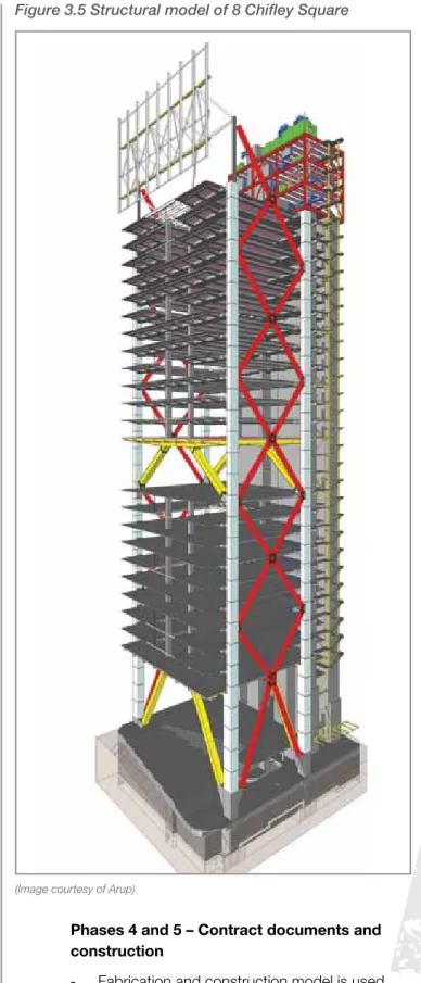
2.3.3 Structural modelling ...35
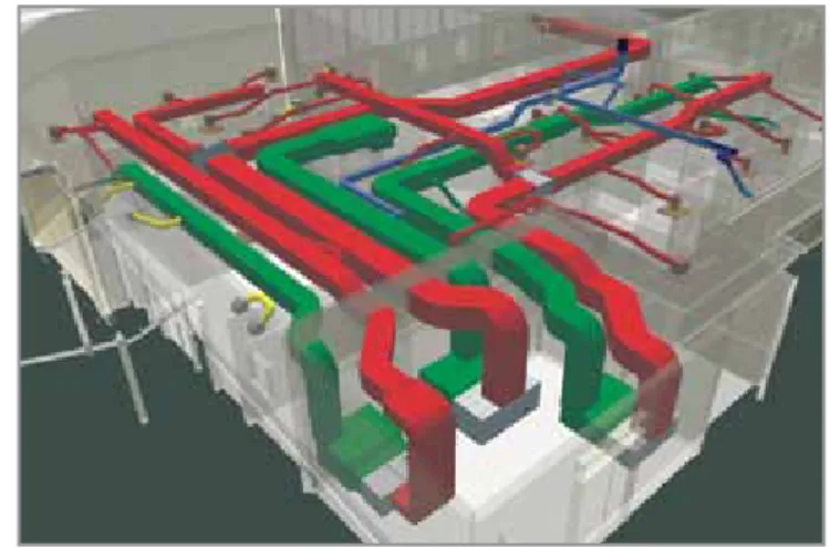
2.3.4 Mechanical, electrical and plumbing (MEP) modelling...35
2.3.5 Electrical modelling ...35
2.3.6 Hydraulics modelling ...35
3.0
Discipline modelling, analysis and simulation ...36
3.1 Project definition, planning and pre-design ...36
3.1.1 Document existing site conditions ...37
3.2 Architectural modelling ...37
3.2.1 Phase 0 – Briefing and pre-design ...37
3.2.2 Phase 1 – Conceptual design BIM ...38
3.2.3 Phase 2 – Schematic design BIM ...38
3.2.4 Phases 3 and 4 – Developed design and contract document BIM ...39
3.3 Structural modelling, analysis, design and production models ...40
3.4 MEP modelling, analysis, design and production models ...42
3.5 Cost planning and quantity take-off ...44
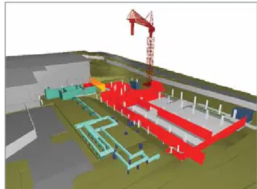
3.6 Construction models ...45
Appendices ...49
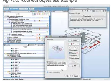
Appendix 1: Model checking and auditing ...49
Model structure ...49
Data on building storeys ...49
Space compliance with project parameters ...50
Duplicate and coincidental model objects ...50
Incorrect object use ...50
Clash detection ...51
Version comparison of models: Reporting versions ...52
Code compliance – egress, accessibility and code checking ...53
Developing custom Rule Sets ...53
Appendix 2: Information Delivery Manual ...54
IDM components ...54 1. Process maps ...55 2. Exchange requirements ...55 3. Functional parts ...55 4. Business rules ...56 5. Verification tests ...56
Appendix 3: Window property sets example ...56
Appendix 4: Model servers ...57
ftp ...57
Appendix 5: Export examples ...58
Revit IFC import/export configuration ...58
Model object types...58
References ...60
Universities, government and industry organisations ...60
Regular web-based newsletters ...60
Technical web-based journals ...60
BIM-related software listing ...60
Design ...60
Analysis, simulation and visualisation ...60
Model merging and management ...60
FM ...60
Books ...61
National Guidelines for Digital Modelling
Preface
Since 2001, the Cooperative Research Centre for
Construction Innovation
has been committed to
leading the Australian property, design, construction and facility management industry in collaboration
and innovation. We have been dedicated to disseminating practical research outcomes to our industry
— to improve business practice and enhance the competitiveness of our industry. Developing applied
technology and management solutions, and delivering education and relevant industry information is what
our CRC is all about.
We look forward to your converting the results of this applied research project into tangible outcomes
and working together in leading the transformation of our industry to a new era of enhanced business
practices, safety and innovation.
John V McCarthy AO
Dr Keith Hampson
Chair
Chief Executive Officer
Acknowledgments
The CRC for
Construction Innovation
provided the major funding, industry research leadership and
coordinated the development of
National Guidelines for Digital Modelling
and accompanying
Case
Studies
.
The
Construction Innovation
project team members are:
Project Leader
Tom Fussell (Project Services
Queensland Department of Housing and Works)
Project Manager
National Digital Modelling Guidelines — Scott Beazley (QUT)
Project Manager
Case Studies — Guillermo Aranda-Mena (RMIT University)
Researchers
:
Guillermo Aranda-Mena, Agustin Chevez, John Crawford, Bilal Succar (RMIT University)
John Hainsworth —Arup Australasia
Simon Hardy — Bovis Lend Lease
Shane McAtee, Garry McCann, Richard Rizzalli — Mirvac
Paul Akhurst , Chris Linning — Sydney Opera House
David Marchant — Woods Bagot
Joyce Law, Phillip Lord, Dean Morse — Brisbane City Council
Paul Crapper — Building Commission
John Spathonis — Qld Dept of Main Roads
Scott Beazley, Robin Drogemuller, Stephan Gard, David Nielsen — Queensland University of Technology
Guillermo Aranda-Mena, Ron Wakefield — RMIT
Integrated Digital Modelling Taskforce
Chair: Andrew Gutteridge (AIA)
Representatives from the following organisations served on the taskforce.
Association of Consulting Engineers Australia
Australian Institute of Architects
Australian Institute of Building
Australian Institute of Quantity Surveyors
BuildingSMART Australasia
National Guidelines for Digital Modelling
The project participants
Industry
Government
Research
Our thanks go to all those who attended and contributed to the success of this publication through their
participation in the workshops held in Sydney, Melbourne, Brisbane and Perth.
Construction Innovation
also wishes to thank and acknowledge Colleen Foelz (
Construction Innovation
and edenink) for managing the production of this publication, as well as Sue Ferguson (itzdesign) and Gail
Cartwright (wordwright) for their design and editing respectively.
Introduction and structure of guidelines
1. Introduction and structure of guidelines
1.1 Introduction
1.1.1 Building Information Modelling
The term Building Information Modelling (BIM) is widely and increasingly used within the building and construction industry. It is also a term which can cause confusion rather than providing clarification. Unfortunately it means different things to different people, and we don’t propose to offer yet another definition here. We will, however, try to describe some characteristics of BIM that may be helpful.
For the authors of these guidelines, a model needs only two essential characteristics to be described as a BIM model. The first is that it must be a three-dimensional representation of a building (or other facility) based on objects, and second, it must include some information in the model or the properties about the objects beyond the graphical representation. Three-dimensional models without information, whether based on objects or line/arc/ circle representations of the building, may still be useful, but they do not qualify as ‘BIM’.
Within this description, there is a very wide range in the richness and complexity of the building model created. In a simple form, BIM models can be prepared for a single discipline and contain minimal information. The model can also provide for the integration of the contribution from many or all of the disciplines involved and be rich with useful information for contractors, trade contractors and facility managers in addition to the design consultants. In this second form, the model approaches or achieves the status of ‘virtual building’ where issues can be explored and resolved digitally before the building is created physically on site.
The degree of difficulty in migrating from the first to the second of these forms is significant, and the journey needs to be approached with caution and patience. Both forms can be described as BIM, but the gap between them is such that the significance of the term in one case is vastly different from the other.
BIM will continue to be used as a shorthand way of describing digital modelling, but it may be more
helpful in discussion if we use terms that more precisely describe the nature of the model being considered.
1.1.2 Integrated practice
Integrated practice or integrated project delivery (IPD) are terms that are increasingly used to describe a move toward greater collaboration between members of a team that can include design consultants, the contractor and some specialist trade contractors.
Ideally, this integration will begin during the early design stages of the project, where the contributions of all parties can be incorporated with greatest benefit and least cost.
The challenge is to develop effective and affordable ways to form and manage the team, while still maintaining a demonstrable level of competitiveness.
Some of these issues continue to be considered by teams such as the AIA Integrated Practice Task Force and a working group formed by the Australian Procurement and Construction Council (APCC) and the Australian Construction Industry Forum (ACIF).
IPD can, with benefit, be established in an industry based on former technologies, but it will work better if developed in conjunction with high-end BIM.
The adoption of truly effective virtual building, and potentially off-site manufacture, will require the development and adoption of IPD for its effective implementation.
1.1.3 Sharing information
Not all members of the consulting team will be working in the same or compatible software packages and the membership of the consultant team will inevitably change between projects. The challenge then is to facilitate an exchange of information between the consultant team or with the wider IPD team. That challenge has at least two facets.
The first is the range of software being used, which in many cases communicate with each other only with great difficulty or not at all. The International Alliance for Interoperability (IAI) — buildingSMART — has worked for more than a decade to develop a common standard Industry Foundation Classes (or IFCs) for the exchange of information between programs. When fully achieved, it may deliver a degree of interoperability in the construction industry similar to that in the banking world, where any of us can use our credit cards to access money through teller machines owned and operated by a bank other than our own. The concept of IFCs is described below.
The second is the way in which the same software family is used by different practitioners, which can also make collaboration a frustrating and often difficult task. This was much in evidence in the use of 2D CAD in the industry over the past 30 years, and created problems that were avoidable if practices had widely adopted a common methodology for the way that the tools were used. These guidelines are intended to provide the beginnings of the conversation and collaboration across the Australian construction industry that might lead to the development and adoption of common standards that are truly ‘national’ and facilitate much better flexibility and opportunities for collaboration in BIM than would otherwise be the case.
1.1.4 Industry Foundation Classes
Industry Foundation Classes (IFCs) were developed to reduce the technical risk in projects by
supporting the exchange of information on building projects between the various participants through the life cycle of a project. The development of IFCs has been driven from the software development side of the industry. Software vendors realised that supporting a single standard for information exchange would reduce their development costs considerably (through not having to support a range of exchange standards), and would assist the purchasers of software by improving the content and quality of information that could be exchanged. They were called Industry Foundation Classes because they were intended to support the entire industry, by acting as a foundation for software development and information exchange, through the definition of standard classes within software.
The vision for the capabilities of the IFCs can best be described with an example.
Take a concrete column. This may be initially positioned by the architect’s sketch designs as part of a notional building structure within the model. This information will then be passed across to the structural engineer, who will import the information on the structure into structural analysis software.
The structural design will then be refined and the final information for the size of the column, grade of concrete and reinforcement configuration will be added to the construction documentation.
The estimator can then attach unit rates to the formwork, concrete and reinforcing steel for the column, which will be included in the cost estimate for the project.
The constructor will also use the quantities for formwork, concrete and reinforcing steel, together with productivity factors to generate a Gantt chart for the project, including the column.
The constructor could then use the combination of Gantt chart (sequence and duration of tasks) to generate a 4D (space + time) visual animation of the construction process to allow the various subcontractors to coordinate the construction activities.
Ideally, the IFC model for the project will be updated through the construction process and an ‘as constructed’ model will be provided to the facility manager on handover. This could form the basis for management of the facility throughout its life, and could be updated as various components and systems are updated. This could then be used to plan the
refurbishment and eventual demolition of the building.
It should be noted from the above description that the IFC model of a project will contain information about the components that make up a building, the processes used to construct and maintain it, and the various organisations that have played roles in this process. Geometric information is only a part of the total information that is retained and is stored as part of the ‘object’ definition within the IFC model, together with all of the other information necessary to support the operations described above.
Introduction and structure of guidelines
1.1.5 Changing context of project
documents
The transition from drawings to BIMs as the means of design collaboration requires consideration of the nature of the new digital environment.
How have we worked in the past? In the traditional process, we use certain types of documents to ‘carry’ the information needed by a project partner. For example, manual drawings or 2D CAD describe a building by independent 2D views (drawings), plans, sections and elevations. Editing one of these views requires that all other views must be checked and updated if necessary, a clumsy and error-prone process that is one of the major causes of poor documentation today. In addition, the data in these 2D drawings are graphical entities only (e.g. line, arc, circle). The work practice of sharing drawings has not evolved past converting them from hard copy to digital documents. Although we can take advantage of the graphics in 2D CAD data much more easily (at the receiving end), the process is primarily a drawing type, suited for contractual estimating and construction, being used as a means for sharing building design information. Specifications are produced in a separate process to fully describe a building.
For example, a reflected ceiling plan defines the architectural concept chosen for the ceiling, and becomes a framework for the several services consultants who need to coordinate their fittings and fixtures with the layout.
BIM provides us with the potential to integrate the entire project information into a digital database specifically for built facilities instead of the
disjointed hard copy currently used. This database is an integrated description of a building and its site comprising objects, described by accurate 3D geometry, with attributes that define the detailed description of the building part or element, and relationships to other objects (for example ‘this duct is located in the storey LEVEL 9’ of a building).
Digital modelling technology has a huge impact on the nature of practice. The building models created can still provide traditional drawings, but can produce far more information that can be used for other purposes in automated processes.
The major difference is the use of the intelligent content of BIM, where objects are defined in terms of building parts and systems (e.g. spaces, walls, beams, doors, building storeys). Instead of sending a plan (the most common document used to inform a project partner of the scope of the topic under consideration), we can now use a model.
1.1.6 Implications for project delivery
with BIM
Three areas of current practice will be affected by building modelling implementation.
Technology implications:
- Software and hardware limitations
- Implementation of the new technologies (e.g. web portals, GIS, laser scanning)
- Need for development of greater
interoperability and integration of softwares for the whole project life cycle
- Development and demonstration of industry-ready exchange protocols
- Handling of very large model file sizes and techniques for sharing information
Process implications:
- Changing work practices and relationships (e.g. IPD vs traditional practice)
- Need for guidelines of common industry practice (e.g. use of exchange protocols and data content)
- New jobs created with different skill sets and responsibilities
- Value added to the models in different time frames
- Greater focus on information management over whole project life cycle, not just the construction phase
- Co-location of project team for critical phases of design collaboration
Policy implications:
- Need for industry standards
- Government or organisation commitment and resourcing for BIM implementation
- Risks of sharing model data and the need to protect intellectual property, legal, insurance, risk, responsibility issues and cost
- Quality Assurance (QA): can others trust your model and data?
- New definitions of services and fee splits, with levels of model detail and categories of information to be specified
1.1.7 Project collaboration process
Virtual Building is worth adopting even if only used by a single discipline, but its greatest productivity benefit is gained when used in multidisciplinary collaboration, with the interoperability of different softwares.
A principal objective of collaboration is to allow partner disciplines to take responsibility for a specific aspect of the project. For example, a services engineer measures the performance of the architectural design and sets environmental measures. The architect has had some preliminary dialogue about the structural system, and now an analysis is needed to refine structural concepts, set out, member sizes etc.
Contrast this with the use of a conventional 2D drawing with limited types which is used to inform the collaborator. This requires extensive one-to-one discussions, and information additional to the set of data required to carry out the task.
Process definition is weak in the industry at present due to:
- its unrecognised value
- the almost impossible task of achieving it in the absence of common industry languages - current work practice agreements
- the lack of robust tools that support the definition and auditing of data.
Productive use of BIM is dependent on the development of defined processes.
A list of possible generic objectives for collaboration will seek to:
- use a reference/master model as the basis of a discipline design
- measure the performance of selected criteria - analyse the behaviour of systems, usage etc.
- coordinate a subsystem with the master model - support an industrialised manufacturing/
assembly application.
In each case, the receiver has a defined role to perform and the collaborators both need to ensure that the required information is available.
There is also a need to define the ‘how’ of data exchange. The ability to export and import building model data between different propriety softwares, based upon agreed standards and protocols, is required. Only then can the richness of the data and its relationships be maintained, during repeated exchanges.
This is a big challenge for the industry.
1.1.8 New methods of practice —
‘integrated project delivery’
IPD describes new ways of working together. The use of building modelling can assist IPD through an earlier engagement of contractors and subcontractors in project delivery through collaboration, alliancing, ‘lean construction’ or other ‘non-traditional’ methods.
Productivity benefits come from the collaborative generation, sharing and re-use of project data. This will mean that project teams will be structured in different ways; work patterns changed with redistribution of effort to earlier design phases ‘design vs design development/coordination’; risk and responsibilities shifted to different participants and different project stages; client expectations and re-configuration of fees due to project information created at different phases. Design process changes
Digital Modelling can greatly enhance the productivity and quality of the design and construction industries to support traditional practice through greater visualisation and communication, higher quality documentation and integration of project data. BIM uptake is worthwhile even if only used this way.
Construction process changes Digital modelling enables more accurate off-site fabrication; finer detail construction scheduling; coordination and communication with subcontractors, designers, owners and authorities;
Introduction and structure of guidelines
less need or no need for shop drawings and as-built documents produced by updating the 4D model used for scheduling and construction management as the building is constructed. Maintenance and operation process changes Project information is available in an accessible and structured format; greater digital linkages with other business processes are possible, and higher quality digital information which has not been manually re-entered.
1.1.9 The guidelines context: Why the
need for guidelines?
The purpose of these guidelines is to assist in and promote the adoption of BIM technologies in the Australian building and construction industry, and try to avoid the uncertainty and disparate approaches that created inefficiencies with the implementation of 2D CAD over the past three decades.
The guidelines are also part of a larger CRC for Construction Innovation program that seeks to encourage increasing digital modelling practice in the whole building and construction industry. There are two related CRC for Construction Innovation research projects:
• 2007-01-EP Interoperable Standards Development
• 2007-03-EP Collaboration Platform Project (BIM Model Servers)
Formative basis for the guidelines
The guidelines represent a broad approach to the task — more a ‘Managers Guide to BIM’ — outlining the process changes necessary for industry implementation, rather than a prescriptive standard. The document seeks to promote the development of consistency within the industry which is also ‘simple and flexible’.
The guidelines are not a ‘standard’ that codifies industry practice in a formative standard, like the more comprehensive USA, Norwegian, Danish and Finnish standards. Australian industry BIM usage has some way to go before it can be considered to be a mature technology, and so the guidelines should be seen as a first step towards unifying industry standards of practice.
The guidelines have been informed by lessons learnt from organisations and projects that have implemented integrated digital modelling, including the associated case studies; research; and feedback from seven industry workshops held between July and November 2008 in five Australian capital cities.
The guidelines provide information to assist in creating well-structured IFC and non-IFC-compliant digital models that will allow the sharing of data between disciplines; for the procedures and formats of data exchanges between disciplines; and for digital model management, coordination, merging and use of aggregate project digital models.
Outputs of the Australian Institute of Architects Integrated Practice taskforce have been included in the jointly developed BIM practice diagram — ‘Towards Integration’.
To be successful, the process of developing and adopting appropriate principles will depend on the active support and participation of the members of the industry in a collaborative and flexible way. The focus of the guidelines is the process implications of BIM implementation The process implications are the most pressing for the industry to address, but the technology and policy implications, although also urgent, will be framed by how new BIM tools are employed and new modes of practice emerge using new processes. This will be an iterative, creative process.
1.2 The potential of digital
modelling
The object-orientated model is more valuable because the properties and relationships within the objects enable useful information to be derived directly or by simulations or calculations.
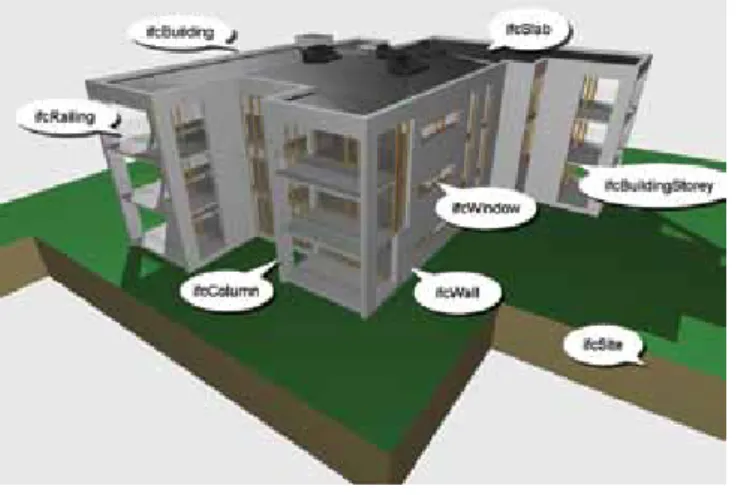
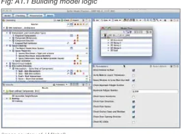
Figure 1.1: BIM example — key concepts
(Image courtesy of J Mitchell)
Figure 1.1 illustrates a project comprising a building on a siteincluding storeys, which contain spaces and building elements such as walls, doors, windows, slabs and columns. It is not just 3D geometry, but is rich in data embedded in the properties of the objects.
The building model:
- allows the integration of a number of discipline models to enable coordination and clash detection of the 3D building geometry - is a database which enables the geometric
representation and building information to be connected in new ways (e.g. specifications potentially can be generated directly from the database using information included with the individual objects in the model)
- can be used to create a 4D construction scheduling and planning model, linking objects with construction activities to test construction strategies, buildability and sequence options. Cash flows and progress payments can be monitored through a 5D model linked to the 4D construction model
- can be updated with ‘as-built’ project
information for building operation and facilities management (FM)
- improves the quality of design decisions by facilitating multidisciplinary collaboration in more frequent and faster design iterations and option development
- quickens the decision-making process through better communication of information that is available earlier and is more accurate, to shorten the time for design and construction - reduces on-site waste by enabling more off-site fabrication, and optimisation of design solutions
- enables new business and procurement models to be considered
- facilitates developing and comparing design options for environmental sustainability during the formative design stages and reporting on expected design performance.
Digital models can help to resolve the puzzles of constructing buildings, like the Lego instructions that show specific objects, with particular relationships, added at a construction stage, in a particular location.
The practice focus changes from drawing or specification production to creating information for incorporation into a database for the project life cycle.
Therefore the quality and consistency of this database is crucial to BIM implementation.
1.3 Quality of models: Well-formed
model building
For a model building to be of good quality it needs: - to be well structured — where the appropriate
tool is used to create the objects; objects are geometrically precise; and the model is structured for intended analysis or exchange - to have the appropriate information required by
the receiver - to be verifiable.
Model checkers are a new type of tool for BIM that exploit the intelligence of BIM objects, to verify model quality (a ‘spell checker’ for building models).They can confirm that models are consistent either to internal office standards, external client standards or to statutory regulations.
For example, model checkers can compare design model options and highlight variations, or analyse architectural and structural model alignment of geometry, location, openings etc.
See Appendix 1 Model checking and auditing for an in-depth explanation and examples.
1.4 Types and uses of models
A range of different types of building models can be created that are used for varying purposes. Pre-design, briefing or massing models:
- For space planning and program compliance/ code checking, where only the external form of the model is used for volume definition or planning approval
Design models:
- Visualisation models that represent detailed properties of the building — shape, materials, lighting — and are models which may also simulate interaction and movement
- Models used to simulate and verify building properties such as: thermal performance, energy use, structural calculations, acoustics, heat flows, Life Cycle Costing (LCC), Life Cycle Analysis (LCA) and environmental sustainability - Building services models: system analysis/
simulation
- Design coordination and clash detection - 4D scenario planning — staging of work for
large complex projects, or continued use of adjacent spaces being refurbished and emergency simulations
- Optimisation, virtual prototyping or optioneering
- Operation simulation and space management. Construction models:
- Clash detection, 4D construction sequencing/ scheduling, prefabrication coordination, 5D predicted cash flows
Fabrication models:
- CNC manufacture, construction sequence, temporary works, off-site fabrication and procurement
FM models:
- Asset management, resource use monitoring, operation simulation.
1.5 Model usage over whole building life
cycle
The consideration of CAD/BIM use has normally only been associated with the design phase of project delivery.
Models can be created and used over the range of project phases in a building’s life cycle. Fundamentally, they enable sharing between consultants, sharing with the construction team, sharing with the owner/facilities manager and generally with any stakeholder in the project that has a need for information. The ‘building digital database’ can be applied to the earlier pre-design stage as well as the construction and post-construction stages, where there are considerable potential benefits. The planning, design and construction stages of a project might be three to four years duration, in contrast to the operation and use of a building at 50 to 100 years. So an accurate and durable database can be a powerful and valuable management tool.
Common or shared information that is required by a number of participants needs to be identified and the responsibility for its creation and maintenance allocated and managed. This will help to avoid duplication and variations of the same object and its associated data, which may create errors and inconsistencies in the project database. The structure and quality of the data is vital and has to be integrated to enable its efficient use and re-use over the project life cycle. This object data will change and develop as the project progresses, when more detailed information is required for increasingly complex analysis/simulation and communication.
It is also likely that the ‘ownership’ and responsibility for some data will be passed on to other participants as the project progresses. For example, an architect may initially add columns and plumbing fittings to a model, but ‘hand them over’ to the structural engineer and hydraulic engineer respectively for their specialist contribution.
1.6 Model development phases
Ideally, building models develop over time with increasing levels of detail and complexity, but in a different way from ‘traditional documents’. There is a need to re-define the type and detail of information required as models develop and when this data is likely to be required.
Model development, as a linear development will seldom occur, can be described in the following general phases:
Phase 0 – Briefing/Pre-design
- Clarification and formalisation of the different requirements and restrictions of the project at design brief stage and proposed delivery time frame
- Client requirements: room schedule and functions, capacity, sizes and relationships. Budget and financial constraints
- Legal requirements: zoning, Building Code of Australia (BCA), regulations, infrastructure, environmental requirements - Site constraints: soil etc - Preparatory BIM of existing
buildings, structures and services on site
- Detail level: coarse 3D massing model, information in document form: legal, analysis, design briefs, building model may contain ground, surrounding developments, GIS information, extent of existing and new infrastructure, supply networks, basic services etc. - Costing: project feasibility and
project budgets
- A capability is emerging that enables the transfer of basic functional requirements into an initial model and the subsequent audit of the spaces and functions provided in the model compared to the briefed requirements
Phase 1 – Conceptual design
- Clarification at an early stage of the project of the overall concept and functional properties of possible project solutions, updated project brief
- Building’s overall form, structure and relationships to surroundings, plus rooms and their relationships - Volumes of building’s external
geometry in simple format - Checks volume can contain
rooms specified in room schedule: interaction between modelling volumes and rooms
- Able to extract areas and volumes at overall level for estimating, analyse estimate of gross and net areas differentiated by function (usable vs circulation areas), and analysis of area efficiencies (area/ plant spaces)
- Can be used for early negotiations with authorities
- Can be used for simulation of light and shade on building and surroundings
- Can be used as basis of design competition for consultants - Detail level: building, rooms,
function, geometry/location - Costing: cost planning. Phase 2 – Schematic design
- Basis for decisions on selecting conceptual solution — the model to reflect the functional and physical structure of the building at an overall level
- Layout of rooms and building elements in general (e.g. footings, walls, structural floors, roof) - Building elements have geometric
shape and location, building envelope
- Detail: building elements, preliminary finishes, building property data
- Basis of basic 4D/5D model - Cost: Updated Cost Plan, Updated
Cash Flow, Updated Life Cycle Cost Plan
- FM: model of existing buildings at Phases 2–3 where detailed construction information is not required for FM purposes. Phase 4 – Contract documents
- Basis for invitations to tender, estimating, tenders and construction planning
- Information of building elements detailed for tendering and quantity take-off
- Need to be able to extract parts lists and descriptive bills of
quantities (BOQ), produce drawings where necessary corresponding to traditional drawings: general assembly, details
- Used for builder as basis for production planning
- Final coordination of all disciplines with checks for clashes, discipline model consistency
- Detail: building elements, final finishes, building property data - Cost: Updated Cost Plan, BOQ,
Detailed Object Definition. Phase 5 – Construction
- Basis for construction
- Used for construction planning, scheduling (4D)
- Contractors, subcontractors and product suppliers information required
- Previous performance requirements replaced with specific attribute data, and new data added — price, supplier, guarantees, time
Introduction and structure of guidelines
- Used to develop basic structure for assessment of building’s overall physical and functional properties, used for spatial coordination between disciplines
- Used for preliminary assessment of evacuation, fire, simulation of indoor environment, lighting, thermal, acoustic performance
- Can be used for early tendering - Building objects shown in simple
outline, without specified attribute data (e.g. a ‘generic’ wall object used, not a ‘270 double-brick cavity wall with exterior face brick and interior render and paint finish’) - All openings in walls, structural
floors and roofs shown in general detail
- Detail level: building elements, geometry/location, preliminary building property data
- Cost: benchmark cost planning, estimating, design cost checks, elemental cost , planning objects at increasingly granular levels (2–4), preliminary Life Cycle Cost Plan - FM: model of existing buildings at Phases 2–3 where detailed construction information is not required for FM purposes. Phase 3 – Developed design
- Basis for the authorities’ consideration for approval; coordination tool for the parties in the project; confirmed project brief - Sufficient information for approval
by authorities
- Building elements given attribute data (e.g. door with specific ‘fire rating’)
- Use for structural resolution of conflicts
- Objects specified as construction types with structural make-up in principle — cavity walls specified and shown
- Detail: building elements, finishes, production/process, product data - Cost: priced BOQs, quantity
take-off, quotation systems, 5D, contract administration
Phase 6 – Post construction/Facilities management
- Setting up ‘as-built’ documentation - Model with updated building
elements, components and properties
- Data used from discipline models for FM including operation, maintenance, renovation, extension - Detail included in the model at
this stage: building elements, finishes, function, geometry/ location, building elements properties, construction, product data, operation and maintenance manuals
- Cost: maintenance and replacement modelling, and management information about cost of plant and equipment, maintenance, warranties, operation instructions etc.
The adoption of modelling will change some of the traditional processes. The distinction between schematic and developed design is blurring, and it is anticipated that before long we will simply have a design stage. Even then, the boundaries between design and documentation and the boundaries between disciplines will become less distinct.
1.7 Object data levels
The objects that go to make up a virtual building will vary in their level of detail. As the project proceeds, building objects may be represented with more detailed geometry and with additional or different information attached to the objects. Consequently, more detailed objects replace generic objects and can then provide more accurate analyses and simulations of building performance.
Highly detailed objects are unnecessary, undesirable and expensive in terms of storage space at initial stages.
‘Detail levels’ is a useful concept for obtaining agreement about content of objects at different stages. This will be necessary when defining the extent of information required at formal exchanges. Level A
- Strategy and performance criteria based on volumes and areas
- Planning activities, concept development - Non-geometric, briefing data or line work,
areas, volumes zones etc. - Block model
- Conceptual cost allowance (e.g. $ per m2 of floor area, $ per hospital bed, $ per parking space)
- Total project construction duration or phasing of major elements
- Environmental requirements Level B
- Generic objects in visualisation/concept models to allow for ‘digital prototyping’ - Generic elements shown in three dimensions
with maximum size, and assumed system types
- Preliminary time scale ordered for appearance of major activities
- Estimated cost based on measurement of generic element (e.g. generic interior walls or doors)
- Specific room requirements can be attached - Approximate quantities of materials for
preliminary environmental analysis Level C
- Specific objects in detailed model, engineering design for digital prototyping
- Specific elements confirmed 3D object geometry, dimensions, materials, capacities, connections
- Time-scaled, ordered appearance of detailed assemblies
Introduction and structure of guidelines
- Estimated cost based on measurement of specific assembly (e.g. specific wall type: 70 interior steel studs with 10 painted plasterboard both sides)
- Precise quantities of materials with percentages of recycled/locally purchased materials
- Accurate analyses and simulations based on specific building assemblies and engineered systems for engineering calculations, visualisation clash detection, construction sequencing, cost planning and estimating Level D
- Detailed objects in production model for shop drawing/fabrication for purchase, manufacture, installation, specified fabrication and assembly detail including construction means and methods (cranes, man-lifts, shoring etc.) - Specific manufacturer selections
- Precise analyses and simulations based on specific manufacturer and detailed system components, committed purchase price of specific assembly
- Manufacturing logistics procurement Level E
- As-built objects — for operation and FM, actual record costs, purchase documentation - Commissioning and recording of measured
performance
- Maintenance and operation requirements - These object detail levels may correspond
closely with model development levels in ‘traditional’ practice, but should be varied to suit alternative project delivery methods
1.8 Modelling implementation
The use of modelling can be adopted for projects in differing ways. The Australian Institute of Architects (AIA) diagram, ‘Towards Integration’, which has been developed jointly by the AIA’s Integrated Practice Taskforce and the CRC for Construction Innovation, seeks to describe these possibilities graphically in defined stages. This is intentionally a simplification of what is a complex and evolving process to assist in developing awareness of modelling implementation. It is also
a vocabulary to assist common understanding, and has already been a valuable communication tool for the range of professionals in the building procurement, design and construction industries. It is intended and expected to develop over time. The diagram is arranged in four major stages, each with two subdivisions.
Stage 0 – 2D documents 0A Manual drafting 0B CAD 2D drafting Stage 1 – Modelling 1A 3D CAD modelling 1B Intelligent 3D modelling Stage 2 – Collaboration 2A One-way collaboration 2B Two-way collaboration Stage 3 – Integration 3A Local server 3B Web-based server
Stages 0A, 0B and 1A represent pre-BIM and are not addressed in the guidelines. A large part of industry practice is still operating at this stage. Stages 1B, 2A and 2B are the main focus of the guidelines and describe the first stages in the adoption and use of BIM. They also represent that part of the industry which is implementing BIM. The evidence is that most practitioners are currently at stage 1B. 3A and 3B describe technologies and processes hosted on model servers which are not addressed in detail in these guidelines. They are considered separately in the CRC for Construction Innovation Research Project 2007-03-EP Collaboration Platform Project – BIM Model Servers (see Appendix 4: Model servers for a brief description). These model servers are yet to be implemented in the Australian industry, but are currently being used for research at UNSW and QUT.
Introduction and structure of guidelines
Towards Integration diagram
1.8.1 Digital modelling: 1B – Intelligent 3D
modelling
High quality single discipline model
This well-managed model is for internal use, and to produce traditional documents for coordination with other consultants and stakeholders. It enables better capture, integration and cataloguing
of project information as it is being created. Efficiencies are leveraged by using BIM software to its capabilities and to enforce resolution of design to greater detail.
A well-constructed model will reveal building issues in early phases that can be addressed immediately, rather than leaving them to be resolved during the construction phases. This requires modelling procedures and standards, so that building model objects are digitally created and connected in consistent ways.
Better visual communication is possible through quick and accurate creation of views, especially 3D views and sections, for all project participants and automated drawing production and coordination. Automated model checking is possible in authoring software or with specialist model checking software to identify geometric clashes or inconsistencies to assist with QA (e.g. Solibri Model Checker and Navisworks can also check by using project specific ‘rules’ or parameters). Widespread industry capability at Level 1B can have a significant effect on the quality of project coordination and documentation.
To achieve broad adoption of BIM at this level of capability would be a significant advance. Requirements of models
- Appropriate BIM tools used for all objects (e.g. all walls created with Wall Tools)
- Precise geometric sizes and locations for all objects
- Objects fully populated with correct properties and attributes
- Information embedded or linked in appropriate and consistent manner
Products possible
Traditional views/drawings/documents can, if required, be automatically extracted and internally consistent: automated 2D plan, sections,
elevations, details, automated schedules, quantities, e-specifications, 4D construction scheduling, 3D visualisations, perspectives, sun studies and animations. Extracts are possible for quantities, areas, volumes etc.
Challenges
While good progress is being made in the adoption of modelling in the industry, there are a number of significant challenges that will constrain future developments until they are resolved. Some of those challenges are:
- lack of an adequate classification system for Australian building information (see Section 1.10.5 Emerging building information classification system)
- lack of design library objects with well-constructed information rich objects in open format (see section 1.10.3 Need for Australian object libraries)
- lack of manufacturers information in usable format with 3D geometry and attached data. No agreed industry minimum properties of objects defined (e.g. window properties: 3D geometry, model number, cost code, ‘U’ value, fire rating, specification, AS standards, warranty, installation instructions).
Example 1: An architect who already uses BIM software for ’traditional documentation’, 3D visualisations and 2D document production, develops BIM capabilities to construct an accurate, well-structured 3D model, using correct object modelling tools, embedded with object data that can be extracted for a range of purposes. The 3D geometry has data and ‘intelligence’ built in. The objects are semantically rich with relationships which are an essential part of the object’s properties (e.g. a wall object can have defined ways of adjoining another wall object). A wall ‘hosts’ window or door objects within it, as it does in real construction, and exact dimensional relationships can be defined. Coordination of the design and detailing is enhanced by the visualisation of the design and the intelligent relationships enforced by the software.
Example 2: An HVAC subcontractor receives 2D documents and creates an intelligent 3D model that is used for detailed routing of ductwork, coordinating the plant room layouts of plant, ducts, pipework and cables. This model is used to generate a schedule of ducts with identification numbers (IDs), quantities and costs. The 3D model is then sent to a CNC machine to cut and fabricate the ductwork and bar code IDs are added to facilitate site delivery and handling. Large scale 3D perspective views can be issued to the site installers to aid understanding, and minimise site errors, especially for complex plant room set-outs.
1.8.2 Digital collaboration: 2A – One-way
collaboration
One-way exchange of a BIM model file is exported to other participants for visualisation, communication, assessment, analysis, simulation or discipline design.
The feedback to the authoring discipline would be conventional feedback for design and coordination in a traditional format (e.g. paper/digital drawings, email, or sketches requiring no digital model return). The original model is updated in digital isolation from other discipline models, and so model coordination is not an issue.
Purposes of digital exchange
- Visualisation: high model quality is not as important or necessary for initial graphic communication
- Dimensional coordination: basis for 3D geometry use and set-out; model geometry quality is critical for coordination
- Analysis: LCA, environmental or estimating analysis software use. Quality and detail of model and embedded information is critical (e.g. sun studies, lighting analysis with correct information included)
- Model merging: for checking/clash detection Some coordination is required to select compatible file formats, versions, data structures etc, and the agreed formats make it easier for quality control and definition of responsibilities and ownership. Partial models are defined for individual discipline requirements (e.g. no need to export whole architectural model to structural engineer, so a selection of object data is exchanged).
This is a big step forward from1B – Intelligent 3D modelling
Requirements
- Well-made model as per 1B – Intelligent 3D modelling
- Agreed purpose of exchange
- Correct and complete model for the purpose and project phase
- Agreed project settings and parameters: - File naming
- File structure
- Model divisions/separations — model arranged in a convenient way for other discipline usage (e.g. separate multi-level building into storeys and define the divisions: top of structural slab, or bottom of structural slab)
- Coordinated system and building reference point
- Software/exchange protocol (e.g. dwf, IFC)
- Requirements of other software — objects, space/room and site data etc. - Verification of model quality by model
checker
- Model transfer method — file, database, model server
- Definition of partial model data
requirements; data required ‘downstream’ - BIM information levels to be exchanged - Expected information that will survive or
not get changed by exchange
- Notification of errors, conflicts, clashes - Agreed template file with project-specific
parameters for more consistent and reliable results
Examples
- A partial architectural model is exported to a structural engineer to share project dimensional and geometric set-out and object properties.
- A model manager imports two or more discipline models to perform clash detection/ coordination and reports back issues, but with
- Structural engineer exports model to steel shop detailer/fabricator for detailed design and fabrication
Challenges
- Software incompatibilities/interoperability problems – incompatible versions of software - Chance of loss of some embedded object
data or geometry errors
- Model needs to have an agreed structure for geometry and associated data
- QA definitions
- Need to change collaboration methods and relationships
- Ownership, risk and responsibility for exchanged data
1.8.3 Digital collaboration: 2B – Two-way
collaboration
The common BIM model file data is shared by two or more project participants in an iterative collaborative process. A significant amount of coordination is required to establish compatible file formats, versions etc. and the correct selection of objects and their mapping settings.
The iterative design process is greatly enhanced by access to analysis softwares and increased feedback. This can produce better decisions and tighter integration of disciplines.
A project could be made up of a number of discipline models that, when combined, better describe the whole (e.g. discipline models that share project geometry and object properties for visualisation, communication, assessment, analysis and simulation contribute to better discipline design and coordination of aggregate project model).
Purposes of digital exchange
- 3D geometry used for clash detection for Design Phase
- Creation of Project Life Cycle BIM Model - For construction/fabrication for limited trades
only for coordination and clash detection - For analysis or simulation of building
performance
This is a major step forward from 2A – One-way collaboration
Requirements
- Well-made model as for 2A – One-way collaboration
- Agreed purpose of exchange
- Correct and complete model fit for the purpose and project phase
- Agreed project settings and parameters: - common coordinate system - common building reference point - model management/coordination
- definition of partial rights/access to model - definition of partial models
Challenges
- Identification/control/documentation of authorship/ownership of amended model - Has it been amended to conform to agreed
standards/requirements to allow import back into original software?
- Is it compatible?
- Defining project standards and enforcing them - Software incompatibility/interoperability
problems
- Chance of loss of some embedded object data
- Need to change collaboration methods and relationships
- Round tripping — what works, what gets lost, what gets corrupted?
- QA definitions - Handover definitions
- Authorship, ownership, risk and responsibility of exchanged data
A project, in practice, might have some disciplines collaborating at different levels (e.g. architectural and structural at Level 2B, and all other discipline collaboration at level 2A).
1.9 New types of jobs and skills
New skills and knowledge are required to create, coordinate and manage the process of modelling, as seen in the case studies. These new skills and roles are still emerging and are as yet hard to define. There will be opportunities for those able and willing to shape new services that progress the contribution of models to the intended outcomes. The role and contribution of experienced technical staff capable of generating and manipulating models in any discipline has grown and is likely to continue to do so for the immediate future. While not rivalling their professional partners, they have a growing responsibility for the creation, communication and analysis of the information that is at the heart of the model.
1. Generic skills for modellers and discipline model managers
- Creation of models and object - Editing models
- Coordination and merging contributions for team members
- Analysis: managing structural analysis and design softwares, extraction of quantities for estimating/cost planning or ordering of materials, thermal assessment, LCA, sunlight and lighting studies and interference checking
- Simulation: solar studies
- Viewing: building coordination on site 2. The role of the project model manager
- Coordination and management of project models. This is much more than a re-badged CAD manager as there are new processes and relationships to manage and new challenges in the integration of multiple disciplines into a common model. - Project model manager tasks:
- establish and manage project standards and protocols
- report to design manager or discipline manager
- check and merge models, write custom project rules for model checking
- implement QA
- archive model files
- establish and manage the structure of team and technology
3. The role of the information model manager
- Coordination and development of organisation modelling standards and practices across projects and project teams
- Coordination of the scope and structure of models
- Licence to promote modelling outcomes and maintain company knowledge base - Information focus from architect (e.g. R rating, embed information on bits of the model)
- Maintain project and object product database into the future
1.10 Challenges for BIM implementation
(issues beyond the guidelines)
1.10.1 Disruptive vs evolving
implementation
This is the ‘human factor’ that has significant impact for industry, especially at the management level. A quote from the case studies
‘... that BIM cannot be implemented through a gradual progression from legacy CAD to BIM. Some indicated that adopting BIM concepts and technologies requires a mindset of ‘revolution’; a process that cannot evolve from replicating legacy CAD standards and procedures. BIM is perceived as a ‘disruptive technology’ that requires quite significant changes to the design and documentation philosophy. This disruption will necessarily include some ‘pain’ which needs to be absorbed and mitigated over time and through deliberate effort.
It follows that adopting BIM may necessitate ‘leaving behind some CAD advantages’ like customised CAD libraries, scripts and other established documentation standards. This shedding of legacy data and procedures is considered — by some interviewees — as a prerequisite for successful adoption of BIM principles and processes.
Management has to be aware of both the opportunities and challenges associated with BIM.
1.10.2 Model users’ differing views and
expectations of model information
BIM, being such a broad concept and encompassing all participants in the building industry, will bring a diverse range of views, experiences and expectations. Therefore an awareness of the requirements of other parties is necessary.
A wall, for example, is seen in very different ways by the following:
- architect: layout, size, finish, colour, texture - structural engineer: load bearing or non-load
bearing
- mechanical engineer: enclosure objects with physical thermal properties
- quantity surveyor (QS): quantity extraction, object specification and cost
- contractor: item to have fabricated off site or assembled on site, with cost, delivery time, construction time, sequencing
- subcontractors: a number of subcontractors may contribute to a single wall — structural framing, lining, plastering, painting, electrical, hydraulic services
- FM: surface to maintain as part of a room or building.
1.10.3 Need for Australian object libraries
Accessibility to product information is emerging as a crucial issue for the successful adoption of BIM by industry. This constraint has been most obvious with design practices that first adopt BIM when they discover that libraries of building elements, furniture and equipment etc. rarely suit their needs. This has led to many consultants creating their own, time consuming, library objects and then finding it difficult to exchange data. Information can be lost, partially lost or corrupted when exchanged, and this can diminish faith in BIM. For example, a curtain wall system after exchange might be in the correct location and height, but doors within that system might end up in different locations, thus corrupting the integrity of rooms/spaces, and the links in the hosting model’s database.
Internal tools in the BIM software have generally good shape editors, and users add rudimentary material properties. However, these libraries are restricted to only a few aspects of product usage that are primarily focused on material or cross-sectional (or presentation) attributes that support documentation needs and correct finishes for visualisation.
While current BIM users have developed their own libraries (from conventional product literature and media), the advent of IFC-based collaboration had made these limitations an even more critical impact as comprehensive material, structural, thermal behaviour and acoustic performance attributes are missing to support their corresponding disciplinary analyses.
The model objects will need to:
- be sponsored, endorsed or created and be maintained with specification details by product manufacturer, bureau, or third party company. They should be controlled and checked before being added to open libraries. Governments could be the generator and custodian of the libraries
- conform to accepted local classification system
- support performance-based specifying and monitoring: use of parameters and/or filter sets, provide QA for specifiers to be checked against project brief, and display if changed for checking
- support code compliance software - support e-commerce — web enabled for
coordination, tendering, ordering, tracking delivery, installation, progress payments and maintenance requests.
Accommodate levels of object data Any object will need to accommodate an
increasing level of detail appropriate for successive project phases.
For example, cost and schedule data for a reinforced concrete column:
Level A – m2 (not differentiated from building and spaces)