Features:
nDigitrax SoundFX™ Sound System -Your locomotives will sound in scale like the real thing with SoundFX™
Customizable 8 Bit Sound 3 simultaneous voices
Downloadable Soundwith Digitrax PR2/3 and SoundLoader software 4 Megabit Onboard Sound Memory
1 Watt Sound Output
Cam input-synchronized steam-chuff option for steam loco use nDrop in Light board replacement for easy install.
nFactory 13mm round 8 ohm speaker
nSmart Power Management-no more booster or programmer shutdowns! No extra equipment needed to program or run
nSoundFX™does not require an external rate sensor to vary workload. nDigitrax LocoMotion®System-Your locomotives look like the real thing.
The Digitrax LocoMotion®System makes them run like the real thing, too! nSuperSonic motor drive for silent operation.
nDigitrax FX3Functions-Control lights and functions for prototypical light-ing effects and on/off control:
nTransponder ID Equippedready for transponding on your Layout nProgram CV’s using any Digitrax Compatible Control system without
having to buy any extra equipment nDirect mode programming nOperations Mode Programming
nDecoder Reset CVwith or without speed table reset.
nMotor Isolation Protectionhelps prevent damage to your decoder. nBasic, Advanced & UniVersal Consisting
n2 Digit and 4 Digit Addressing nDCC Compatible
nDigitrax “no worries” warranty nFCC Part 15, Class B RFI compliant
N Scale
SDN144K0a: Drop in Decoderwith SoundFX
™
1 Amp/2 Amp Peak, 4 FX3200ma Functions, Includes 13mm 8 Ohm round Speaker
SDN144K0a
SoundFX
™
Drop in Mobile Decoder for Kato N Scale E8/PA/P42 and similar
Locomotives. Preloaded with selec-table E8 or F40 Sound Schemes
Parts List
1 SDN144K0a Decoder drop-in with Sound FX™ 1 Factory wired 13mm round 8 Ohm speaker. 1 330 uF capacitor (For Optional Install) 1 Instruction sheet
Installation Information
See the Digitrax Decoder Manual for complete decoder test procedures, instal-lation instructions, programming and technical information. Digitrax manuals and instructions are updated periodically. Please visit www.digitrax.com for the latest versions, technical updates and additional locomotive-specific installation instructions. After market pre-machined frames may be available.
1. Carefully remove the Kato E8 shell. Remove the analog light board, trucks, gear towers drive shafts, motor and all parts and carefully save these parts in the correct order for re-installation. This should leave a bare frame ready to be modified to accomodate the speaker. Isolate the track pickup springs from the motor tabs using supplied Kapton tape.
2. The factory 13mm speaker may be mounted in the diesel tank or at the rear, as shown in this installation example in Figure 1. For this rear installation carefully drill an e.g. 1/2” hole down through the rear frame area of the bare frame that is clear of the rear gear tower mechanismand exits at the under-side of the frame. This is the port the speaker needs for proper operation. With a larger drill that clears the 0.513” diameter speaker case, or dremel Figure 1: SDN144K0a installation in Kato N- E8 frame preparation.
Kato light board track pickup springs
rear gear tower
Kapton tape around both track-springs to isolate motor tabs at sides
N scale E8 shell
SDN144K0a
speaker mount hole machined in rear-upper block
rear led removed motor tab retain clip
13mm Factory speaker Kato E8 frame
grinder open up the top e.g. 0.150” part of the hole diameter so that the speaker will fit snugly in the top and clear the shell. For this E8 rear instal-lation version the unused rear LED should be clipped off flush with the rear pcb edge to provide clearance for the speaker and wires.
3. Reinstall the parts from step 1 in reverse order, substituting the SDN144K0a decoder for the original light PCB, making sure to isolate the long track pickup springs from the motor tabs using the supplied Kapton tape. Be sure the motor tabs connect properly under the motor tab retain clip. Place the 13mm speaker in the mounting location created in step 2.
Be sure to inspect the speaker diaphragm for magnetic debris, dirt or dam-age, which will affect sound quality. Other speaker(s) may be substituted and mounted in combinations as long as the total impedance on the black/red speaker wires is greater than 8ohms. Note that the rear upper installation in this E8 example provides better sound than a diesel tank installation, although this is quite subjective.
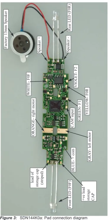
4. (Optional) Functions for other lights etc., may connected to the pads identi-fied in Figure 3. These function leads effectively switch the track voltage, so LED’s and 1.5V lamps will need current setting resistors installed exter-nally as required.
5. (Optional) In a E8-B unit installation the included 330uF/25V electrolytic energy storage capacitor may be installed at the front of the frame after the front LED is clipped off, and a space machined out to accept this capacitor. Solder the capacitor terminals to the marked pads in Figure 2. Be sure that the capacitor case and leads do not short to the frame or damage to the decoder may result. For other locomotives the 330uF capacitor may be Figure 2: SDN144K0a Decoder installation in Kato E8 - reassembled.
motor tab retain clip track pickup springs
rear gear tower Kapton tape around both
track-springs to isolate motor tabs at sides
N scale E8 shell
right Motor tab
13mm Factory speaker mounted rear-upper in machined through hole
unused or a smaller capacitor with at least 16V rating for 12V N-scale track voltages may be used, if desired.
6. Inspect the installation before testing the sounds and replacing the shell. In particular Ensure motor tabs make proper contact with the decoder motor pads.
7. Connect to active DCC track power from a compatible DCC system and select the factory default address 03 to enable sounds for testing
8. Be sure F8 (mute) is OFF to allow sound output, and then press F1(bell) or F2 (whistle/horn) ON to hear these associated sounds.
9. Customize sounds by programming Sound CV’s to adjust the desired con-figurations, as shown in the following tables of Sound FX CVs. CV60=0 sound scheme is an E8 and CV60=1 is an F40. Other locomotives may be dowloaded from the Digitrax web site and conveniently programmed using a PR3 programmer. This “K0” form-factor PCB may be used in a number of other locomotives by adjusting the LEDs and applying a little modeling ingenuity.
Speaker Mounting and baffle or enclosures.
The sound performance of any attached speaker(s) is greatly affected by the mounting system and required baffle or rear enclosure space. Depending on the locomotive model and construction and speaker chosen it may be necessary to modify the frame or parts of the internal shell to make room for one or more speakers and enclosure.
For the Kato N scale E8 installation shown here the whole body acts as a sound baffle. Obviously the space inside this N-scale locomotive is limited since the frame is configured for maximum weight and pulling effort, and the installation shown here is just one variation of the possible locations for a speaker.
The baffle is used to isolate the speaker diaphragm front sound waves from the “out of phase” rear sound waves. This minimizes sound cancellation, particu-larly at lower frequencies. For most efficient sound generation, the cubic space of the baffle should be as large as practically possible, and the baffle walls should be acoustically rigid so not to allow acoustic interference. be sure that there is a tight seal from the speaker sides to the wall of the baffle. In this example the speaker should fit snugly in the drilled mount hole. Of course, you can substitute an alternate after-market speaker of the maximum size for the locomotive you have. For example, you can wire in the SDN144K0a in a modern HO-scale locomotive with a high-efficiency can style motor as long as the stall current is less than 1 amp at the track voltage in use. In this case it is possible to change to a larger speaker(s) that has a “high bass” or similar enhancement.
For best operation it is useful to connect the optional 330uF storage capacitor to help overcome pickup dropouts due to dirty track.
Figure 3: SDN144K0a: Pad connection diagram Speaker + Speaker -Factory 13mm Speaker Rear LED (F0R) Front LED (F0F) lead of storage cap (striped) +ve lead storage CAP GRA Y - left motor CAM input GREEN- F1 YELLOW - F0R VIOLET - F2 WHITE- F0F BLUE- + com ORANGE- right motor
Customizing Your Decoder
Your Digitrax SDN144K0a Sound FX decoder is ready to run and will operate and generate sound using address 03 with no additional programming. On your Digitrax system, simply select the locomotive’s address and the sound will start. On some DCC systems, it is necessary to select the locomotive address AND send a command to start the sounds.
For a more prototypical railroading experience, your decoder can be customized for your specific locomotive by programming some of the Configuration Variables, or CVs, available. Digitrax Sound decoders can be programmed using either the paged mode or operations mode method on a programming track or with the operations mode using the main line. See the Digitrax Decoder Manual or the Digitrax web site for more information. Initial Test and Programming:This decoder is preprogrammed and tested
with an E8 diesel locomotive sound scheme, and is ready to operate on fac-tory default address 03. Before customizing the decoder it is useful to run it on the factory default address 03 to check the installation. The following sections show how to change the locomotive address and customize the decoder
For more information on general decoder installation and programming tech-niques and examples visit the www.digitrax.com
Changing the Decoder Address
The first CV most people change is the decoder address. This allows you to independently control each loco with a unique address. Digitrax decoders are shipped with CV01 (AD2), the two digit address, set to 03. Following is a brief description of how to change the decoder address with a Digitrax DT series throttle. See your Starter Set Manual for complete programming instructions. 1. Place the loco on the programming track. Go into Program Mode on your system.
On DT400/DT402 press PROG. On DT300, DT100 & DT200 press RUN/STOP & FN/F0.
2. Choose AD2 for 2 digit addressing or AD4 for 4 digit addressing (DT400/DT402 and DT300). (Ad for DT100 & DT200, see set manual for 4 digit instructions). 3. Choose the address you want to set up for the decoder.
4. Complete address programming. On DT400/DT402 press ENTER. On DT300, DT100 & DT200 press SEL.
Note:CV29 must also be programmed to enable 4 digit addressing, this is done automatically by the DT400/DT402 & DT300 but not on earlier throttles.
Using this decoder in other locomotives
The factory supplied sound project loaded into the SDN144K0a is for E8 (default) or F40 diesel locomotives, selectable with the value in CV60. If you want to install it in a different locomotive, you can simply load a different sound project for that type of locomotive. The cam input is available for steam installations where you want to synchronize chuffing.
Digitrax LocoMotion® System
Your locomotives look like the real thing, now you can make them run like the real thing, too. Digitrax decoders incorporate torque compensation for smooth as silk operation. You can also program CVs that control momentum, 3 step and 128 step speed tables, switching speed, normal direction of travel, scaleable speed stabilization and more to take full advantage of the Digitrax LocoMotion®System.
Momentum-CV03 & CV04
Momentum is part of the LocoMotion®System. Acceleration is controlled by
CV03 and deceleration by CV04. Both come from the factory set to 000. A range of 000 to 031 is available for both accel and decel. Try CV03:003 and CV04:000 as a starting point for experimenting with momentum.
Speed Tables-How the Loco Responds to the Throttle
With Digitrax LocoMotion®, there are two types of speed tables: 3 Step Tables
and High Resolution 28 Step Tables. Please see your Decoder Manual for a discussion of the 28 Step Tables. The 3 Step Tables are set up by programming 3 CVs: Start Voltage (CV02), Mid point Voltage (CV06) and Max Voltage (CV05). These values are set at 000 at the factory. All have a range of values from 000 to 255. We recommend the following CV values as a starting point for experimenting with speed tables.
Loco Type V Start V Mid V Max
CV02 CV06 CV05
Switcher
Concentrated low speed. Limited top 002 038 064
speed
Road Switcher
Prototypical top speed w/evenly 002 048 098
distributed curve from 0 to top speed
Mainline Loco
Quick increase to cruising speed then 002 128 154
Other LocoMotion
®Features: Switching Speed, Normal Direction of
Travel & Scaleable Speed Stabilization (Back EMF) Features
Switching speedis controlled by CV54. The factory setting is 000 for OFF. To turn on the switching speed feature, program CV54 to a value of 001. When this feature is on, use F6 to activate and deactivate switching speed. With the feature on the throttle’s target speed is effectively reduced by about 50% and the effects of accel and decel programmed into the decoder are reduced by 1/4. This is useful for yard switching operations.
Normal Direction of Travelis controlled by CV29. See your decoder manual for additional information on the settings for CV29.
Decoder Reset CV08
Decoder resetlets you reset all CV values to the initial factory settings. To reset all CV values, program CV08 to a value of 008. You also have the option of resetting all values except the 28 speed step tables. To do this,
program CV08 to a value of 009.
Digitrax SoundFX™
System
Digitrax SoundFX™ lets you make your locos sound in scale like the real thing!
The SoundFX™ sound CVs in the range of CV140 to CV256 let you cus-tomize your decoder without having to reprogram or change the installed sound scheme.
Standard decoder CVs in the range of CV01 to CV120 operate the same as for a non-sound FX3Digitrax decoders (they control motor and light functions
etc.) CV58 is used as Master Volume, and CV60 is used to select an alternate scheme, if provided in the sound project.
Sound CV155 is provided to select Diesel engine “notching” modes. The default of CV155= 00 provides “automatic notching” that changes the diesel RPM settings at 8 distinct throttle speeds that are controlled by Sound CV132.
Sound CV155=01 selects “semi-automatic notching” mode that allows F6 ON to increase the notch from the current throttle setting and F7 ON to decrease back towards the lowest current throttle notch setting.
Sound CV155=02 selects “manual notching” mode that allows F6 ON to increase the notch setting and F7 ON to decrease the notch setting irrespective of the throttle setting, which controls just the motor speed. The decoder’s sound scheme can be reloaded using a Digitrax PR2 or PR3
pro-grammer and a sound project file (for example AC4400.spj) from the Digitrax Sound Depot web site. Typical sound downloads take between 50 and 100 seconds depending on the project complexity and file size. The following tables show the CVs used in this decoder version and how it is
Sound FX DC Operation Mode
CV# Used For
Range
[default val]
01 2 Digit Address [03]
11 Sound Time Out, 06 = Sound ends when loco address is
de-selected, 00=Sound stays on after loco is de-selected [06]
29 Configuration [06]
49 Forward Light (FOF) -Headlight [0]
50 Reverse Light (FOR) -Reverse Light [0]
51 Function 1 [0]
52 Function 2 [0]
58 Master Volume (F8 ON used for Muting) 0-15 [9]
60 Factory Scheme Select: 0=E8 diesel, 1=F40 diesel [0]
132 Notch Rate [127]
135 Mute Volume [0]
140 Prime Mover Volume 0-64 [60]
141 Bell Volume (Min=0, Max=64) [25]
142 Horn Volume (Min=0, Max=64) [60]
143 Time-Scattered Air Effects Volume 0-64 [30]
145 Misc Vols 0-64 [40]
146 Bell Ring Rate (1=24 milliseconds) 1-100 [07]
147 Air Drier Rate (1-about 2 seconds) 1-64 [02]
148 Compressor Run Rate [30]
149 Air Compressor On Time [20]
150 Horn Setup (Default=0, Playable Horn=1,
Alternate Horn=2
[0]
151 Auto Coupler Sequence Threshold Value-Peak speed to
allow auto coupler/brake when direction change occurs and F3 is ON
0-64 [48]
152 Project Author ID, Digitrax=221 [221]
153 Project ID, E8/F40 dual scheme [25]
155 Notching/Slip Mode: 00=Automatic,
01=Semi-Automatic, 02=Manual
Digitrax SoundFX™ decoders will operate on smooth DC power. The sound will not start until approximately 5 volts is applied to the track and there will be no “start up sound.”
SDN144K0a Troubleshooting
If the sound does not start in the decoder
1. Make sure you have selected the locomotive address on a throttle. The sound will not run unless the locomotive is addressed in the system. Make sure F8 is OFF.
2. Check your installation to make sure the decoder is installed properly.
Function #
Used For
Notes
F0 Lights
F1 Bell
F2 Horn/Whistle CV150 selects horn
F3 Coupler crash Auto coupler/brake set by
CV151 max speed
F4 Air feature disable F4 off enables pop-off,
drier and starts compres-sor
F5 Diesel = Dynamic brake
Fans
F6 Diesel = Notch Up Notch UP if CV155=01 or
02
F7 Crossing Gate Airhorn
or;
Diesel = Notch DOWN
Notch DOWN, if CV155 = 01 or 02
(Crossing Gate Horn active if CV155=0)
F8 Mute Control F8 ON is muted
F9 Brake squeal
F10 Crossing Gate
Airhorn Sequence
F11 Handbrake
If the sound output sounds distorted
1. Check the speaker cone for magnetic debris that may have collected there. Debris on the speaker will cause a loss of sound quality and must be removed. 2. Be sure that the CV58 volume is not set at a level that is too high for the speaker being used. For impedances below 32ohms (e.g. 8 to 30 ohms) set this volume setting lower to ensure the 1 watt output rating is not exceeded. If the sound in your decoder shuts down after you stop it and you are not using a Digitrax system for control.On some DCC systems decoders are not addressed by DCC packets after the locomotive is set to 0 speed. In this case after the CV11 timeout elapses (6 second default), sound will “shutdown.”. To defeat this feature, set CV11=00 to remove the timeout and shutdown. To make sounds, the decoder must have a command addressed to it at least once. If you have trouble reading back CV’s on the programming track, this may be due to insufficient current draw on the SDN144K0a motor or function leads. Of course you can always just re-program the CV value into a CV to get the desired results, even though reading CV’s might not work.
OPS mode is recommended for writing to (programming) all CVs except CV01, CV17 & CV18 (2 digit and 4 digit addresses). If a second DCC decoder is present that is not Sound FX compatible then correct read back of CV data is not possible,since the NMRA CV read back was not designed for multiple decoder read back.
The SDN144K0a plays an F40 Diesel scheme, but I want the default E8 scheme. If the factory scheme has not been erased, program CV60 to a value of 0 to reselect the E8 scheme. Alternatively set CV60 to 01 to change to the F40 sound scheme.
I have loaded a new scheme but the CV’s and Functions are not what I expected. Load the sound project you programmed and then select the “view>project description” menu and then read the text file on the screen that defines how that project in particular uses CV’s and Functions for sound generation and configuration. Even without a programmer you can get
SoundLoader and the sound projects from the Digitrax web site and review the descriptions on your compatible PC.
My speaker does not have a polarity mark. Speaker Polarity is simply used to ensure when more than one speaker is being used that they can be wired or “phased” so the input causes the diaphragm to move in the same direction. It can be ignored in a single speaker case.
When using my LT1 and test kit when I blow the Horn the decoder resets. Using the LT1 test kit and protection resistor is good to check the decoder is safely connected, but when a loud sound like a horn is activated the protection resistor limits the available power too much, so the decoder resets. Simply test full volume sounds on normal track power after connections check OK. If vol-ume overloads decoder and loco slows, set CV57=0 to turn off BEMF.
Warranty & Repair
Digitrax gives a one year “No Worries" Warrantyagainst manufacturing defects and accidental customer damage on all Digitrax products.
That's it! A simple, straightforward warranty with no tricky language!
Visit www.digitrax.com for complete warranty details and instructions for returning items for repair.
Made in U.S.A. [R0] 2443 Transmitter Road Panama City, FL 32404 www.digitrax.com T 850-872-9890 F 850-872-9557 Available Computer Interface Computer Interface Decoder Programmer Decoder Programmer Sound Programmer Sound Programmer TM
EEMPIREMPIRE B BUILDERUILDER
Super Super