Robin Sharp
Jens Thyge Kristensen
Department of Information Technology, DTU
September 2000
Contents
1 Introduction
2
2 Phases of a Project
2
2.1 Models of the Software Development Process . . . 4
2.2 Requirements Analysis . . . 6
2.3 Modelling and Design . . . 9
2.4 Implementation . . . 12
2.5 System Test . . . 14
3 Roles in a Project
15
4 Project Management
17
4.1 Activities and Activity Scheduling . . . 174.2 Risk Management . . . 19
4.3 Project Records . . . 20
5 Software Project Documentation
21
5.1 Goals for documentation . . . 225.2 The structure of the documentation . . . 23
5.3 Presentation rules . . . 23
5.3.1 Terminology . . . 24
5.3.2 Language and style . . . 24
5.3.3 Typography . . . 25
5.4 The user's manual . . . 25
5.5 Source programs . . . 26
5.6 References . . . 27 1
1 Introduction
These notes give a short introduction to Software Engineering as it is used in software development projects of moderate size. Software Engineering is the discipline which deals with the specication, development and evolution of software systems. Even quite simple software systems commonly have high inherent complexity, a fact which often leads to software products having defective functionality, being delivered late or in other ways not living up the users' expectations. The techniques described in these notes have been developed over the years to help developers control this complexity in a manner which leads to the development of reliable products which correctly reect the customer's requirements. The notes fall into two main parts. In the rst part, we consider the actual process of carrying out a development project, its phases, and the results from each of these. In the second part, we consider some aspects of software projects which are more oriented toward management: the roles played by the various participants or stakeholders in a project, and some techniques used for managing projects, in the sense of planning and monitoring the use of resources.
These notes have been written to help participants in the Informatics Projects course during their second year of study at DTU, but we hope they will be generally useful as a short introduction to the subject. For the reader interested in further reading matter, there are a number of excellent books on this topic. We particularly recommend the latest (Sixth) edition of Ian Sommerville's book \Software Engineering" [Som01].
2 Phases of a Project
Software development is an engineering process, and software projects { like most engi-neering projects { fall naturally into phases, each of which focusses on a particular aspect of the development process. Four phases are usually identied:
Requirements analysis:
The objectives to be met by the software system (together with its hardware platform) are dened in collaboration with the intended users of the system.The result of this phase is a requirements specication document which is approved ✍
by all participants.
Modelling and design:
Starting from the requirements specication, the \real world" concepts employed by the users are expressed in terms of mathematical models or other abstract descriptions, and the components of the software system are identied and their functionalities specied.The result of this phase is a design specication document which is approved by the ✍
project management.
Implementation:
The components of the software system identied in the design speci-cation are implemented in an executable programming language and tested individ-ually to check that each component correctly implements the functionality required of it.The result of this phase is a set of code modules written in the chosen programming language, a test scheme for each module, stating how it has been tested and giving ✍
the results of the individual tests, and technical documentation describing the internal working of each module.
System test:
The individual program modules are integrated into a complete system, which is then tested to check that overall software requirements have been met. This is sometimes known as external test, as the system is tested \from the outside", without regard for its internal structure.The result of this phase is a test scheme for the entire system, stating which tests ✍
have been carried out and what the results were.
We shall describe these phases in more detail later in these notes.
Most student projects make do with the four phases described above, but in projects in industry, further phases are added, such as:
Deployment:
The system is set in operation on the user's system and its acceptability for the intended purpose is checked. This phase may result in a formal, legally binding acceptance test, where the user takes over the system as a correctly delivered item { and pays the agreed sum to the supplier.Maintenance:
After delivery, many systems undergo maintenance, due to a need to:Correct errors in functionality which did not become apparent during earlier
phases.
Adapt the software to a new hardware or software environment. Extend or modify functionality due to new user requirements.
Software companies often discover that maintenance is an expensive and time-consuming phase, which takes resources away from important new development. We shall return later to some things which can be done to reduce this burden.
Finally, it must be noted that the phases described above only refer to software develop-ment. In many projects, the Requirements Analysis and Design phases include elements of Systems Engineering, in which decisions are made as to which elements of the total system are in fact to be implemented in software. The remainder of the system then consists of hardware, existing collections of data (in databases or the like), people performing various functions (with or without the use of computers) and so on. Although in some types of system this can be very important, we shall concentrate in these notes on the design of the software, and assume that the systems engineering task has been carried out.
2.1 Models of the Software Development Process
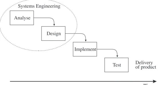
There are several accepted paradigms for the process of software development, in which the phases described above are exploited in dierent ways. These are often called models of the software life-cycle. In the simplest model, known as the waterfall or linear sequential model, the phases of Requirements Analysis, Modelling/Design, Implementation and Test are dealt with as a linear sequence of activities, so that work on phaseN starts when work on phase (N 1) has been successfully completed. This is illustrated in Figure 1.
Analyse Design Implement Test Time Systems Engineering Delivery of product
Figure 1: The waterfall model of software development
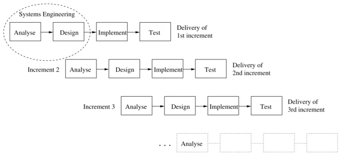
The waterfall model is a classical model of software development derived from models used in other branches of engineering, and was rst described in 1970 by Royce [Roy70]. Although it is widely used, it has attracted a good deal of criticism, as it does not (at least in the simple form illustrated here) describe the essentially iterative nature of the development process. A particular problem is that it implies that the specication, once agreed on, is frozen. If an error is discovered during system test, corrections are therefore made to the implementation rather than the design. This may be the ideal state of aairs, but it is not always a very practical strategy to use in complex systems or in systems which are based on quite new principles, since the development team may simply not have enough experience to nalise the design before attempting an implementation. Modern life-cycle models therefore often incorporate procedures which allow for more experimentation. The simplest example of this type of model is the incremental model illustrated in Figure 2 on the following page. This is an example of an evolutionary model which reects the idea that a software product is produced in a number of versions, each of which is a stepwise improvement on the previous version. For example, it may solve a more complex task,
Delivery of 1st increment Systems Engineering Increment 2 Increment 3 Delivery of Delivery of 2nd increment 3rd increment . . . Time Design Test Design Test Design Test Implement Analyse Analyse Implement Implement Analyse Analyse
Figure 2: The incremental model of software development
include more complete facilities within the given problem domain, oer a more interesting user interface or whatever. The development of each version or increment follows the usual sequence of phases, with each increment staggered in time with respect to the previous one, so that experience from previous designs can be incorporated into the new design. In the gure, each new increment starts sometime during the detailed design phase of the previous increment, but the delay may in some cases be much larger, so that development of the new increment does not start until the previous increment has been delivered. In such cases, the development model begins to resemble the prototyping model to be described next.
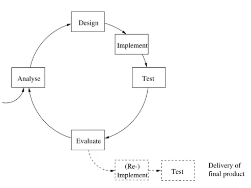
In a prototyping model, all the stakeholders (the users and the developers) recognise that they are unable to reach agreement on a nal specication without seeing the system in action and evaluating its behaviour. The entire development process then takes on the iterative form illustrated in Figure 3. In each iteration, the development team discuss with the users what the system is to do, and go through the usual phases of design, implementation and test. The users are then asked to evaluate the system and to suggest changes, which results in a revised set of requirements, which are then turned into a design, implemented and tested. This cyclic procedure continues until the users are satised with the functionality of the system.
Prototyping relies on the availability of specication and implementation tools which per-mit rapid implementation, and this model is typically employed in software development environments where very high level programming languages { such as functional languages and logic programming languages { are used. This reects the fact that software develop-ment time is more or less linear in the number of lines of code to be written. So a high-level
Test Design Implement Evaluate Analyse final product Delivery of Test Implement (Re-)
Figure 3: The prototyping model of software development
language, which makes it possible for the programmer to express abstract ideas very con-cisely, gives a shorter development time than a low-level one. Since the main idea is to agree on the intended functionality of the system, eciency is not usually an important issue when prototyping is used. If a more ecient version is required, it will be developed subsequently via a (re-)implementation in a more ecient programming language, devel-opment of better algorithms, or the use of hardware platforms with increased performance. This is indicated by the dashed boxes in the gure.
Although prototyping sounds like an ideal way to ensure that the users' wishes are genuinely reected in the design, it in fact often gives rise to disagreements between the development team and the users. This is because the users may believe that they have seen the real product in operation and are thus strongly disappointed to hear that they have to wait for delivery of a version which can be used in practice. Managers of teams which use prototyping techniques need to explain this carefully at the start of the project.
2.2 Requirements Analysis
The purpose of the Requirements Analysis phase of software development is to produce a clear description of what the users require from the nal system. The essential question to be answered at this stage is what is the system to do? It is important not to try to think about how the system is to do this; this is a matter to be considered in the Design phase. Very often, the customer initiates the project by producing a rough description of the
required product. The task of the development team is to ask relevant questions which enable them to turn these rough ideas into a more detailed and precise description of what the system is to do. This is not an easy task. Almost everybody has heard about computer systems which do not full the customer's requirements. Common reasons for this are:
Essential questions were not asked during the Requirements Analysis phase. The requirements were formulated in too imprecise a manner.
The questions were put to the wrong people.
The requirements contained too many low-level details, making it impossible to get
an overall grasp of the problem.
A well-known recipe for disaster, for example, is to ask the customer's top managers what the system is supposed to do, without talking to the sta who will actually use the system. Not only is this poor personnel policy, it also often results in a system which does not reect the way in which data are actually gathered and used in the customer's company. Requirements are often divided into two classes:
Functional requirements:
These describe the functionality of the system and the ser-vices it must provide, the sort of input it must deal with, the form and appearance of the output and so on.Non-functional requirements:
These describe constraints on the way in which the sys-tem must operate, such as time and space requirements, ease of use, security require-ments, requirements with respect to hardware or software platform, standards to be followed and so on.The division is somewhat articial, since requirements which to the user appear non-functional (say, with respect to security) may to the implementor appear non-functional (the system must oer facilities for user authentication). Likewise, ease of use is regarded as a non-functional requirement, but strongly inuences the design of the user interface and the style of features such as help functions and error messages. But this classication is a useful way of structuring the discussion about what is required.
The keywords for Requirements Analysis are completeness and precision. To ensure com-pleteness, you are recommended to make use of a checklist of functional and non-functional requirements which need to be gathered. For the functional requirements, you need to make sure that you understand:
The concepts which are used in the problem which the system is to solve. The mode of operation of the system: interactive, batch-oriented, etc.
The source and form of the input data: numerical, text, from a database, from a le,
via a network, etc.
The destination and form of the output data, analogous to the description for input
data.
The way in which the system is to react to errors in the data: (user-friendly) error
messages, replacement of faulty data by default values, stop the program with an exception, etc.
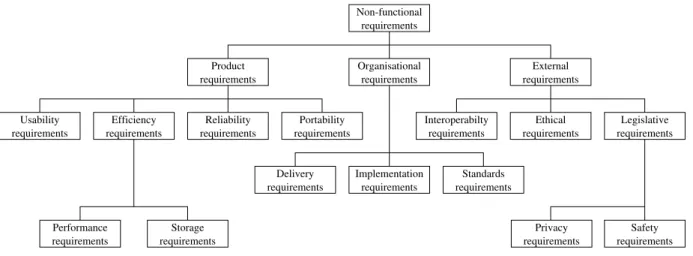
For the non-functional requirements, a longer checklist is required, for example based on the taxonomy shown in Figure 4.
Non-functional requirements requirements Performance requirements Storage
requirements requirements requirements
requirements requirements requirements requirements requirements requirements requirements requirements requirements requirements requirements
Product Organisational External
Efficiency Reliability Portability Interoperabilty Ethical Legislative
Privacy Safety Standards Implementation Delivery requirements Usability
Figure 4: Classication of non-functional requirements (after [Som01]) The main classes are:
Product requirements
specifying the behaviour of the product, including its perfor-mance, reliability, ease of use and portability between platforms.Organisational requirements
derived from policies and work procedures used by the customer and the developers, including the language of implementation, platform (hardware and operating system), standards or norms to be followed, delivery sched-ule for the product and its documentation and so on.External requirements
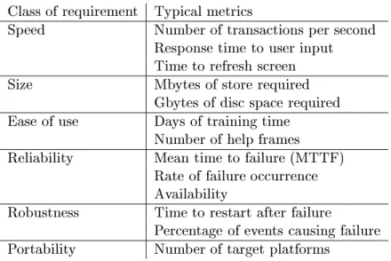
covering everything which is dictated by factors external to the stakeholders' organisations, such as legal and ethical requirements, and requirements related to how the system may aect systems owned by third parties (interoperability requirements).You should aim as far as possible to specify requirements in terms of quantities which can be measured, so that it is later possible to verify that the requirements are met. Table 1 on the following page show some typical metrics used for this purpose.
All the requirements are collected up in the requirements specication. At this stage of the ✍
Class of requirement Typical metrics
Speed Number of transactions per second Response time to user input Time to refresh screen
Size Mbytes of store required
Gbytes of disc space required Ease of use Days of training time
Number of help frames
Reliability Mean time to failure (MTTF) Rate of failure occurrence Availability
Robustness Time to restart after failure
Percentage of events causing failure Portability Number of target platforms
Table 1: Metrics for non-functional requirements
understand them. However, natural language is a common source of misunderstandings, and every eort should be made to use more precise notations, such as mathematical for-mul, whenever possible. Obviously this is easier if the customers are technically minded!
2.3 Modelling and Design
In the Modelling and Design phase of a software development project, a full specication is developed for the software system, so that it can be implemented as an executable program in the following phase. As the name suggests, this phase can be divided into two parts:
Modelling:
Development of a mathematical model or other abstract description of the \real world" problem identied in the Requirements Analysis phase.Design:
Identication of a set of program components which can produce the functionality identied in the Requirements Analysis phase, and specication of the interfaces which they oer to one another.As a very simple example, let us consider a project to develop a small program for simulat-ing the ight of a rocket. The initial functional requirements are that the program should provide:
1. An interactive user interface for input, at which the user should be able to provide a set of data describing the initial mass, thrust, fuel consumption and fuel
capacity of a rocket.
2. A graphical user interface for output, on which the position of the rocket relative to its starting point can be seen in a two-dimensional coordinate system as time passes, the position being evaluated for every 100 ms of the simulated ight. 3. The possibility of simulating several rocket ights with dierent sets of input data
during a single run of the program.
As a non-functional requirement, the customer demands that the position of the rocket in the graphical output should in fact be updated on the screen every 100 ms, so the user of the program can follow a simulation of the rocket's ight in real time.
A (somewhat simplied) mathematical model for describing this problem could be the following dierential equation describing the equation of motion of the rocket:
~F +~gm =
d
dt(m~v)
where ~F is the thrust of the rocket,~g the acceleration due to gravity, mis the mass of the rocket and~v its velocity, all of which are functions of time,t. It is not the purpose of these notes to discuss how to solve this equation in detail, but if you have just an elementary knowledge of the dierential calculus you will realise that this equation can be used to derive an expression for the position of the rocket, ~x, as a function of t.
Just introducing this model also introduces a notation for several of the concepts mentioned in natural language in the functional requirements specication. The next step is then to decide how these concepts are to be expressed in terms of quantities which might appear in a programming language, so that they can be referred to in the descriptions of the interfaces to the various modules which make up the system. Firstly, we need to dene the types used to represent these quantities in the program, for example:
Name Type Description
t integer Time in units of 100 ms.
Fx, Fz real Components of thrust vector at time t (Newtons) vx, vz real Components of velocity vector at time t (m/s) x, z real Components of position vector at time t (m) m real Mass of rocket + fuel at time t (kg)
mr0 real Initial mass of rocket without fuel (kg) mf0 real Fuel capacity = initial mass of fuel (kg) fuelc real Fuel consumption of rocket (kg/s)
and so on. The next task is to design some modules which perform essential, well-dened functions in the context of the problem. For example, we might identify functions with the following types:
type thrustvec = (real * real) type velocityvec = (real * real) type positionvec = (real * real)
type mass = real
type consumption = real
type time = int
input_rocket: unit -> mass * thrustvec * consumption * mass
simstep: positionvec list * velocityvec * thrustvec * mass * time ->
positionvec list * velocityvec * thrustvec * mass * time output_orbit: time * positionvec list -> unit
These types and signatures have been given in a functional programming language, in this case SML. We strongly recommend you to follow this practice, so that the logical design of the program can be completed at a high level of abstraction before attention is paid to the details of implementation. The purpose of these functions is as follows:
input_rocket() inputs a new set of data for a simulation. The user is prompted for a
new set of data, and the function returns the initial mass of the rocket with fuel, a pair of real values giving the x and z components of the initial thrust, the fuel consumption and the initial mass of fuel, as provided by the user.
simstep(pvl,v,F,m,t) takes a list of position vectors, pvl, whose head is the latest
(current) position vector, together with the current velocity vector, v, the current thrust
vector, F, the current mass, m, and the current time, t, and returns the values of all
these quantities at the end of the next simulation interval of 100 ms. The new values are assumed to be evaluated by making use of the dierential equation. The new position vector is appended at the head of the position vector list.
output_orbit(t,pvl) takes a time, t, and a list of position vectors, pvl, whose head
is the latest position vector, and updates the graphical interface to show the path of the rocket up to the given time, as described by the sequence of positions in the list.
These functions need to be controlled by a main program which can deal with one or more ight simulations. In each simulation, a set of input data is obtained from the user, and a simulation is performed corresponding to a number of simulation intervals of 100 ms, starting from the initial positionx=z = 0 with velocity 0, and continuing until either the rocket lands (z becomes 0 again) or the simulation is aborted by the user. The mechanism to be used by the user for this purpose needs to be specied. We shall not go into further details here.
The designs of the user interfaces for input and output are also completed at this stage, and included in a design specication so that the customers can approve them. For example, ✍
100 200 300 400 500 600 700 800 900 200 400 600 800 1000 1200 1400 1600 1800 Time= 1234.5 s Position x (km) Position z (km)
Figure 5: Example of graphical interface determined during design phase
should look as shown in Figure 5. This gure should be supplemented with annotations which explain what the signicance of the text and numerical elds in the diagram is, and where the relevant data come from in the program { i.e. which variables they give the values of, or how they are calculated. For example, the value given for the time at the top left corner of the gure is the value of the current time in seconds, evaluated from the internal quantity giving the time in units of 100 ms. Similarly, the size of the output in relation to the page or screen must be specied { for a graph, for example, rules for scaling the axes to suit the size of the curve must be given.
Some of these decisions may mean that the development team need to ask the customer for more details about what is required. This is quite acceptable. What cannot be accepted is if the development team omit to ask the customer about matters which they are in doubt about, and just make some kind of arbitrary decision { \They probably wanted it like this" or \We'll just do as we usually do".
Exercise:
Several of the design decisions described in the previous section were not actually specied in the original functional specication, as given on page 10. List these decisions. Suggest further questions which it would have been necessary to put to the customer in order to complete the functional and non-functional requirements.2.4 Implementation
In the Implementation phase of the project, the software components specied during the Modelling and Design phase are implemented in some suitable programming language. The language may already have been given as a non-functional requirement during the
Requirements Analysis phase or be selected at the start of the Design phase. If not, it is chosen now.
Since we assume that the Modelling and Design phase ends up with a specication which decribes the software components, their interfaces and the way in which they interact with one another, it should be clear that the Implementation phase just involves developing correct code for each component, in order to achieve the desired functionality. To put it another way: the Design phase ends with descriptions of the components viewed as black boxes, while in the Implementation phase the internal mechanisms of these black boxes are determined.
This is clearly seen in the rocket example, where the functionsimstep evaluates the
posi-tion, velocity, thrust and mass at the end of the next interval of 100 ms of simulated ight time. To do this, it is necessary to develop a suitable algorithm based on the dierential equation. The details of this will depend on how accurate the result is required to be { yet another example of a non-functional requirement which the development team will have to ask the customer about.
Similarly, in the implementation of output_orbit it is necessary to decide whether the
entire list of position vectors is to be plotted on the graph each time the function is called, or whether the previous positions will be remembered, so that it is only necessary to add the information corresponding to the movement which has taken place in the most recent interval of 100 ms. This again will depend on the nature of the facilities available for plotting graphs in the programming environment chosen for the implementation. Maybe the development team will even have to develop these facilities themselves, which may lead them to design additional modules for this purpose.
For an inexperienced programmer, this phase is the biggest challenge. For the experienced software engineer, on the other hand, it is usually the phase which requires least eort, since the external conditions for all of the modules are given.
A useful principle to follow during implementation is that of traceability of concepts. In other words, concepts which appeared in the initial requirements and later on in the (more or less formal) design specication should also be recognisably present in the code. It is not a good idea to introduce completely new notation or ideas at this stage or to change things radically in relation to what was planned. For example, it would be inappropriate and confusing in the rocket ight simulator suddenly to let the time be given by a quantity of type real. Similarly, concepts which have been referred to in the specication should
not just be allowed to disappear in the nal implementation.
An important aspect of the Implementation phase is testing of the modules as they are developed. This is a so-called internal test, in which the developers test out the program unit based on knowledge of how it works internally. A typical aim is to check that all paths through the module have been activated and work in accordance with their specications.
This is often known as a path test. Each test case in a path test uses a set of test data which will cause execution of the program unit to follow a particular path through the code. The tests performed for each module are documented in the form of a test scheme, ✍
which for each test case species:
The purpose of the test case, i.e. what the test is intended to demonstrate, which in
path testing will describe the path to be followed.
The expected result from the test. The test data actually used.
The result observed, and whether this is in accordance with what was expected.
To perform such a set of tests on a program module, the module must be inserted in a small test program which either obtains input from the person running the test or from a le of test data, or which generates test data automatically. The test scheme is included with the program module in the documentation delivered at the end of the Implementation phase.
2.5 System Test
The nal phase in any development project is the System Test phase, whose aim is to check that the complete system operates in accordance with the agreed specications. The system is assembled from its components, and is tested as a whole, without regard for its internal structure. The aim is to check that the system can perform all of its intended functions correctly, and that it also fulls its non-functional requirements, to the extent that these can in fact be tested { this is obviously dicult for ethical requirements, for example!
As in the case of the internal tests of individual modules performed during the Implemen-tation phase, the development team must work out a test scheme, which for each test case ✍
species:
The purpose of the test case, i.e. what the test is intended to demonstrate. The expected result from the test.
The test data actually used.
The result observed, and whether this is in accordance with what was expected.
The point of having such a test scheme is that it makes it possible, if the system is modied or errors are detected at a later stage, to see which tests were originally performed on the system and to repeat them if necessary.
In principle the test scheme should include sucient test cases to exercise the entire func-tionality of the system. In practice this is often infeasible due to the system's complexity,
and choices have to be made. If this is the case, you should remember that it is more important to test the functions which are commonly used than those which are only used rarely.
3 Roles in a Project
Except in cases where a single person performs a project for his or her own enjoyment, projects involve a number of dierent people, who take on characteristic roles. A role corresponds to a \logical person", who performs some kind of function related to the organisation or execution of the project. In projects with few participants, one person may nd him/herself taking on several roles, while in large teams several people may play the same role.
We can characterise the typical roles in a software development project as follows:
The customer:
The customer is the person or organisation who should benet from the result of the software project. Customers are (normally) characterised by speaking a non-technical language, using concepts which are characteristic for the problem area in which they work. Often, the customer has very diuse wishes, and expresses basic and important demands in an implicit manner \between the lines" of the written material which he or she provides. In the nal analysis, the customer denes the overall resources which can be expended on the project.The executive:
This is the person in the software development organisation who controls the setting of the project, and can adjust the available resources. The executive often wants to be informed about the status of the project, its history, and the plans for how it is expected to develop. The executive is mainly interested in expressing things in terms of costs and earnings, whereas the internal details of the project are of little interest.The designer:
The designer is responsible for understanding the customer's demands with respect to the result of the project. After gaining that understanding, the designer must transform the demands into a conceptual frame describing the func-tionality in an implementable way. Thus the designer must be able to handle both the concepts used by the customer and the technical concepts used in software de-velopment. This means that the role of the designer needs to be lled by a very experienced person who is both creative and systematic.Essentially, the designer builds the bridge from the requirements specication to the design specication.
The programmer:
The programmer has to understand the designer's description of the intended result of the project and to transform that description into source code that realises the product.It is also the programmer's responsibility to verify that the functionality of the source code which he or she writes is the same as that described by the designer. This verication is done by appropriate testing, as described above.
It is an advantage to the programmer to have insight into the internal structure of the whole system. This role also demands a certain talent for self-discipline, so that the programmer's creativity stays within the limits set by the designer. Otherwise the work of the programmer could change the project result in an unwanted direction. The programmer must do a pure transformation of the product described by the designer into a working piece of software.
The bookkeeper:
The bookkeeper keeps track of all the material created during the dierent phases of the project, registers the resources used, and keeps track of the degree of completion of the project.The bookkeeper also has to store the items produced in all phases of the project in such a way that they can always be retrieved, and so that all participants can always nd information about the current status of the various parts.
The comptroller:
This is the person who ensures that the result of the project is what the customer has ordered. So the job of the comptroller is to ensure that the functionality of the product is kept invariant throughout the various transformation processes which are carried out during the phases of the project. He must ensure that functions required by the customer do not just \disappear" and that unwanted functions are not introduced.The comptroller has to combine a good overall grasp of the system with a good sense of tact and diplomacy, so the development process stays on track and the people involved keep up a good team spirit.
The project leader:
The project leader must ensure that everyone performs in accor-dance with their roles, and distributes the tasks to the cast. The leader must su-pervise that the tasks are carried out within the limits to resources given by the executive, and if necessary transfer resources between tasks.This role demands a good knowledge of human nature, in order to keep a pleasant atmosphere among the participants involved in the project, whom the project leader must protect from direct critisism from the outer world.
In student projects, where the development team typically consists of one or two students, the customer is the person who poses the problem, while several of the other roles may well be played by the same person. Nevertheless, it is important to be aware of all these roles, so that decisions can be made in a realistic manner. For example, one of the development team may put the project leader hat on from time to time, in order to make a strategic decision about the running of the project, while the next day he or she returns to being an ordinary programmer, in order to get on with the implementation. To get a better idea about project management, you should try to make sure that you realise which role you are playing whenever the project team meet to discuss the project. We will return to this topic in the next section of these notes.
4 Project Management
Project management includes all aspects of getting a project to run on time and within the agreed budget. In this respect software projects are no dierent to projects within other engineering disciplines. On the other hand, software projects are characterised by the product being intangible: you cannot see it developing like a bridge, an airplane or even an item of computer hardware. This makes it more dicult to keep track of what is going on, and increases the need for appropriate written material which documents progress. For projects involving computer systems, project management deals particularly with the following issues:
Personnel:
The allocation of personnel to the development team and the roles which individual people are to play are specied.Resource requirements:
The hardware and software needed for execution of the project is specied, and prices and delivery schedules are determined.Work breakdown:
The project is broken down into activities, and the deliverables and milestones for each activity are specied.Activity scheduling:
The time required to complete each activity, the allocation of per-sonnel to activities and the dependencies between activities are described, and a complete schedule for all activities is worked out.Risk management:
Project risks are identied, the likelihood of these risks arising is estimated and contingency plans are set up for dealing with the risks if they arise. This may result in one or more alternative project schedules being developed. In the initial stages of the project, a plan dealing with all these points is drawn up. As the project progresses, the development team need to report to the management team (who are by no means necessarily the same as the development team) about progress. The management team must lay down requirements for how this reporting is to take place. We have already discussed the question of roles in Section 3 on page 15. The determination of resource requirements is a relatively simple matter and will not be discussed further here. The following sections will discuss the remaining issues in more detail.4.1 Activities and Activity Scheduling
Division of a project into well-dened activities is an essential pre-requisite for being able to manage the project eectively. Within each activity it is necessary to have at least one milestone, which marks the end of the activity. Each milestone must be characterised by a verbal presentation, a piece of documentation or some other tangible item which is to be delivered by the development team. A realistic period of time should be set aside
for reaching this milestone from the start of the activity, and the personnel needed for performing the activity must be identied.
A milestone is an internal project event, and the material which is delivered is intended for the management team. It is often a good idea to associate each milestone with a review, where the management team evaluate the progress which has been made in the project and check the quality of what has been produced. Many methods have been proposed for checking software quality; a simple but eective method which we recommend to you is the walkthrough. Here one or more persons, who have not been directly involved in a particular activity, go through the documentation or program produced during that activity with the people who have produced it. The eect of having to explain what the documentation means or how a part of the program works is in many cases to reveal lack of clarity or even genuine errors, which can then be eliminated.
Some milestones may further be characterised by a deliverable, which is an agreed item to be delivered to the customer. Deliverables may be items of documentation or actual software modules. The number and schedule of deliverables depends strongly on the size of the project and the model of the software life-cycle which is being used. If the waterfall model is used, for example, the minimum set of deliverables would include the user requirements specication, the actual software product and the user documentation. If the customer ✍
requested full insight into the design, the internal program documentation and the test ✍ schemes for internal test and system test would also be delivered.
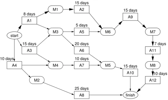
Once activities have been identied and personnel allocated, it becomes possible to deter-mine an actual schedule for the entire set of activities involved in the project. There are a number of techniques (and associated computer-based tools) for nding feasible schedules { i.e. schedules such that the activities are performed with due respect for their dependencies, and such that the same personnel or other resources are not allocated to two activities at the same time. An example is the activity graph shown in Figure 6 on the following page. In the gure, activities are denoted by rectangular boxes, and milestones by oval boxes. Each activity in the graph is marked with the estimated time required for its performance. Dependencies are marked by arrows: an arrow from A to B means that B depends on the completion of A. The heavy path through the graph is the critical path, whose duration gives the minimum time required to nish the project: 55 days, in this case. Delays on any other path through the directed graph do not necessarily delay the completion of the project. Tools for handling activity graphs can often automatically work out how much a given milestone or activity can be delayed without causing the overall project deadline to be missed. An alternative technique to the activity graph is the activity bar chart (or Gantt chart), where each activity is marked on a calendar as a bar which reects its estimated and maximum permissible duration.
start A1 A2 A9 A5 A3 A4 A7 A8 A10 A11 A12 M1 M2 M3 M4 M6 M5 M7 M8 A6 finish 8 days 15 days 15 days 7 days 10 days 15 days 25 days 5 days 20 days 10 days 15 days 10 days
Figure 6: Activity graph for a project
4.2 Risk Management
Risk management is the activity of evaluating risks and contingency plans for dealing with them if they should arise. This is often divided into three parts:
Risk analysis:
Potential risks and their consequences are listed, and the likelihood of each of them occurring is determined.Risk planning:
Plans to avoid the risk or to minimise its eects on the project are drawn up.Risk monitoring:
Each risk is assessed at regular intervals, and its likelihood and eect are re-evaluated.Typical risks in industrial projects include:
Sta turnover in the development team, Change of management,
Failure of a supplier to deliver hardware (or necessary software), Changes in customer requirements,
Imprecise specication,
Faulty estimation of cost or size of system components, Technology changes which make the technology outmoded, Competition from other companies.
Usually, the probability of a risk arising is estimated in a very rough manner (high, medium, low) and its eects in a similar manner as being catastrophic, serious, tolerable (marginal)
or negligible. Obviously, all catastrophic risks and most serious risks need to be taken seriously and a contingency plan needs to be drawn up to deal with those whose probability of occurrence is non-negligible.
Exercise:
Investigate the risks which are likely to occur in a student project, giving estimates of their likelihood of occurring and the consequences if they occur.4.3 Project Records
Activity scheduling relies on good estimates of the duration of the individual activities. Although some general results are known for all types of project, for example that Analysis and Design take about 40% of the resources (see for example Table 2), and roughly how development time is related to the number of lines of code (see Table 3), more detailed estimates for particular software engineering methods and types of software are based on experience.
System Type Phase costs (%)
Analysis/Design Implementation Test
Command and control 46 20 34
Spaceborne 34 20 46
Operating system 33 17 50
Scientic 44 26 30
Business 44 28 28
Table 2: Relative costs of software development activities (after [Boe95]) Type of Software Manpower required (man-months)
Simple application 2:4kLOC
1:05
Auxiliary/service program 2:8kLOC
1:10
Algorithmically heavy program 3:2kLOC 1:15
System program 3:6kLOC
1:20
Table 3: Development costs related to program size
Here 1 kLOC = 1000 lines of source text, and 1 man-month is 1.4 calendar months.
The values in the table are for average programmers. For inexpe-rienced programmers, multiply by at least 4; for experts, multiply by 0.3 (if less than 300 LOC) to 0.5 (more than 1 kLOC).
To accumulate this experience, you should always keep track of how much time you used to perform the various activities in a project. We recommend you to keep a detailed record of this in a project notebook, in which you record the progress of the project (especially ✍
the milestones reached, deliverables completed and documents produced) as time goes by. You can usefully combine this with a list of meetings held and decisions made during the project, so that it takes the form of a project diary. For example, every time you have a project-related meeting of any kind (either internally in the development team or with the customer, external consultant or whatever), you note down:
When and where the meeting took place Who was present
What the purpose of the meeting was What decisions were made
When the project is over, you can learn a lot by looking back to see which decisions were important ones, at what stage things went wrong (if they did), and what it cost to correct dierent types of fault.
5 Software Project Documentation
Software needs to be carefully documented if it is to be useful { almost everybody has experience of poorly documented software products, and knows how time-consuming and frustrating they are to deal with. One of the main reasons for this, as we have remarked above, is that software is intangible, so it is not in general possible just by looking at the product to nd out how to use it or how it works internally. Good quality documentation needs to be produced as part of every serious software project.
Documentation falls into three general categories:
User documentation:
This is intended to tell the user of the software about what the software product can do, and how to install and run it.Program documentation:
This is intended to tell programmers how the program works internally, and how it has been tested.Project documentation:
This is intended for the customer who initiated the software project and for the managers of the project, to specify the requirements and to keep track of progress and use of resources in all phases of the project.In the previous sections of these notes, we have marked important components of this documentation with the sign✍ in the margin. To summarise these:
The design specication
The internal technical documentation of the individual modules of the software. The test schemes for the individual modules from the internal test performed during
the implementation phase.
The test schemes for the complete product from the system test performed during
the system test phase.
The project notebook containing project management information, such as minutes
from all project meetings, management decisions, information about milestones and deliverables and documentation for the use of resources such as time and money. In this section we shall look in more detail at what the documentation should contain and how it should be organised. Much of the section is based on the general ideas presented in reference [Ris00].
5.1 Goals for documentation
The goal of any documentation can be summarised in two points:
The documentation should be useful to the reader. I.e. when consulting the
docu-mentation the reader should
{
get all the information which is needed{
not get information which is not neededThe documentation should be easy to update to a new version of the product.
Note that these goals conict with one another. For example, repeating the same in-formation at several places in the documentation may be helpful for the reader { but it is a nuisance when the documentation is to be updated. Thus the person writing the documentation will have to nd a compromise between these two goals.
You must also remember that the dierent target groups { users of the software, program-mers, managers etc. { have dierent requirements with respect to the documentation, as they have dierent ways of thinking about the product. Indeed, they often dier markedly in their general knowledge of software. For example the secretary who uses an oce system and the doctor who uses a computerised patient data system may only have a very vague idea of what a computer program is or what goes on inside the computer; hopefully this is not the case for the programmers or their managers! When producing documentation you must therefore be able to make descriptions of the same product on dierent levels, and on each level you must be able to write on the premises of a particular kind of reader.
5.2 The structure of the documentation
In a large, industrial-scale project, the items of documentation will typically be produced in the form of separate reports intended for the various target groups mentioned above. In a student project, a single report will normally be sucient. The structure of such a report should follow the generally accepted style of scientic reports, with sections as follows:
1. Abstract/introduction. This gives a short summary of the contents of the report and its structure.
2. The problem to be solved. This should give the reader a general introduction to the problem domain and describe the actual problem to be solved. Key concepts which will be used in the remainder of the report are introduced and dened. A concise description of the underlying theory is given. If a more extensive presentation of the theory is required (for example with long, detailed proofs of particular results), it should appear in an appendix.
3. The requirements specication. 4. The design specication.
5. A general overview presenting the detailed design of the software as implemented. This should describe the relationships between the individual modules, such as the way in which they depend on one another, and the internal working of these modules. Note that detailed program listings should be presented later in an appendix. 6. The test schemes for the system test of the complete software product.
7. A conclusion describing the state of the product as delivered, including any known faults or missing features (in relation to the requirements listed in the requirements specication), and suggestions for improvements.
8. A list of references for literature referred to in the report (see Section 5.6 below). More detailed material which is only of interest to particular groups of readers is usually placed in appendices, for example:
A. The user's manual (for the users). We return to this in Section 5.4 below. B. The project notebook (for the managers).
C. The actual source text of the software (for the programmers); see Section 5.5 below. D. The test schemes from the internal test of the individual sub-programs in the
indi-vidual modules (for the programmers).
E. (optional) Detailed theoretical results, proofs or derivations.
5.3 Presentation rules
In addition to following a more or less standardised way of organising the documentation, it is important to follow some general rules for presenting the documentation in a manner which makes it accessible to the reader.
5.3.1 Terminology
The terminology is the set of terms used to denote concepts pertaining to the software product together with their precise meaning when used in the documentation. Graphical symbols used in gures are also part of the terminology.
As we have already mentioned during our discussion of the design process, a software product should whenever possible be described in terms of accepted concepts, terms and symbols from the problem domain. In general, it is a poor idea to invent completely new terms for well-known ideas, as the reader then has to put much more eort into understanding the documentation, and may well give up. On the other hand, terms from the problem domain have to be used in very precise manner { typically more precise than is usual when people discuss things informally. This may make it necessary to express ner distinctions with more concepts, so one will have to invent new terms { or to dierentiate between terms which (in other contexts) are often considered synonymous.
The basic rules for terminology in documentation are:
Consistency:
Always use the same term (or symbol) to denote the same concept.Dierentiation:
Use dierent terms (or symbols) to denote dierent concepts.Note that these rules are in conict with a stylistic rule requesting the use of a varied language to create a uent text. This stylistic rule does not apply to the terminology of software documentation, where consistent use of terms and symbols is much more impor-tant than linguistic variation.
5.3.2 Language and style
The following stylistic rules should be used when writing documentation:
Use short sentences { avoid long convoluted sentences.
Avoid chattering \small-talk" { and remove sentences which are not essential for
conveying the message of the section being written.
Use gures when appropriate.
The use of gures must be consistent with the written text. Use examples instead of verbose explanations in tutorial material.
Use tables in the text to arrange referential material in a systematic way.
Give gures and tables titles (\captions") which summarise the information supplied.
If necessary, supplement the caption with an explanation of any special symbols or other notation used in the gure.
Literary skills are rather useful when documenting software, but don't get carried away. Use short and concise language { you are not writing a novel.
Make sure to divide the chapters or large sections of the report into sub-sections in a natural way. Each section or sub-section must have a title which gives the reader some idea of the section's contents. Each section should start by telling the reader what the section is about, either directly (\In this section we describe the stylistic rules...") or more indirectly (\The following stylistic rules should be used..."). In some contexts, it can also be useful to tell the reader what he or she is expected to get out of reading the section concerned, and to nish the section with a little summary of what has been presented. You should always try to keep the level of detail constant throughout a section or sub-section; if you need to present a particular subject in more detail, then start a sub- (or sub-sub-)section. For example, the part of these notes which you are reading at present is a sub-sub-section giving detailed rules for Language and Style within a sub-section on Presentation Rules within a section on Documentation.
5.3.3 Typography
Most companies have a corporate standard for setting up documentation, and you will, of course, comply to this standard when working in a company.
At DTU we follow common typographical rules for technical reports:
Write on A4 sheets.
Put title of report, title of course, date, and your name and signature on the front
page.
The margins should have room for holes used to put the report into a binder. Use an easily readable size of characters { the font should be at least 11 pt. Use page numbering.
Chapters, sections and subsections should be numbered. Figures and tables should be numbered.
Use page footing and/or headings.
Larger reports should have a table of contents and an index.
5.4 The user's manual
The user's manual should describe the way in which the product should be installed and run. In particular, it should tell the potential user about:
How to install, start and stop the program.
What input is to be provided to the program in response to particular prompts from
the program, or in connection with particular screen images, forms or whatever. The input should be described as precisely as possible in natural language or a formal notation (such as BNF), so that the user is in no doubt about what is required.
The normal output expected from the program.
Any error messages which may appear, what they mean, and what the user is
ex-pected to do in order to recover from (or avoid) such errors.
5.5 Source programs
Source programs should be presented in a manner which makes it possible to see their structure and which helps the reader to understand how they work.
The following rules will help you to achieve this aim:
Start the listing of each module (class, signature, functor, etc.) of the program on a
new page.
Start each module with a heading in the form of a comment which explains the
purpose of the module, who has programmed it, the version number and date of the current version and other appropriate details which can identify it.
Start each sub-program (method, function, procedure etc.) of the module with a
heading in the form of a comment which explains the purpose of the sub-program, and describes its parameters and results.
Use indentation to help the reader to identify the beginning and end of program
structures such as loops and branching structures (if-then-else, case, etc.).
Make sure that the lines of program text t within the width of the paper and do
not run out over the right hand margin or overow onto the next line.
Comments should give extra information which can not be read directly from the program, such as:
The intention of specic parts of the program. The intended use of declared variables.
Invariants of data representations.
Comments should be brief and they should not clutter the program. The program must be arranged in a way to make it easy for a reader to locate and nd any specic part of the program.
5.6 References
A list of references is an essential part of any scientic or technical report. The references should unambiguously identify the source of any other documents referred to in the text. It is both illegal and unethical to quote or refer to the work of other authors without giving a complete and correct reference, so that the reader can nd the original material if required! The format of a reference depends on the type of work being referred to, i.e. whether it is a book, conference paper, article in a journal, technical report or whatever. All references should mention the name(s) of the author(s) (or editors, if the work is a collection of articles or the like), the title of the item being referred to and the date of publication. In more detail, you should give at least the following information for the following common categories of references:
Book:
Author(s)/editor(s), title of book, publisher, year of publication.Article in book:
Author(s), title of article, title of book, chapter number/page numbers, publisher, year of publication.Conference paper:
Author(s), title of paper, name of conference, page numbers, year.Journal article:
Author(s), title of article, name of journal, volume, page numbers, year.Report:
Author, title of report, name of organisation, year.Some typical examples can be seen in the list of references at the end of these notes. Many text formatting systems make it easy to produce lists of references in suitable formats, and you are recommended to use such a system if it is available to you.
References
[Boe81] B. W. Boehm, Software Engineering Economics, Prentice-Hall, Englewood Clis, New Jersey, 1981.
[Boe95] B. W. Boehm, `The High Cost of Software', in E. Horowitz (ed.), Practical Strate-gies for Developing Large Software Systems. Addison-Wesley, Reading, Massachusetts, 1975.
[Ris00] Hans Rischel, `Documenting Software', Department of Information Technology, DTU, 2000.
[Roy70] W. W. Royce, `Managing the Development of Large Software Systems', Proceed-ings of WESTCON, California, August 1970.
[Som01] Ian Sommerville, Software Engineering, 6th edition. ISBN 0-201-39815-X. Addison-Wesley, 2001.

![Table 2: Relative costs of software development activities (after [Boe95]) Type of Software Manpower required (man-months)](https://thumb-us.123doks.com/thumbv2/123dok_us/10651206.2952842/20.892.191.720.533.689/table-relative-software-development-activities-software-manpower-required.webp)
