Michael Rybalko and Eric Loth
University of Illinois at Urbana-Champaign, Urbana, Illinois
Rodrick V. Chima, Stefanie M. Hirt, and James R. DeBonis
Glenn Research Center, Cleveland, Ohio
Micro-Ramps for External Compression
Low-Boom Inlets
NASA/TM—2010-216351
AIAA–2009–4206
NASA STI Program . . . in Profi le
Since its founding, NASA has been dedicated to the advancement of aeronautics and space science. The NASA Scientifi c and Technical Information (STI) program plays a key part in helping NASA maintain this important role.
The NASA STI Program operates under the auspices of the Agency Chief Information Offi cer. It collects, organizes, provides for archiving, and disseminates NASA’s STI. The NASA STI program provides access to the NASA Aeronautics and Space Database and its public interface, the NASA Technical Reports Server, thus providing one of the largest collections of aeronautical and space science STI in the world. Results are published in both non-NASA channels and by NASA in the NASA STI Report Series, which includes the following report types:
• TECHNICAL PUBLICATION. Reports of completed research or a major signifi cant phase of research that present the results of NASA programs and include extensive data or theoretical analysis. Includes compilations of signifi cant scientifi c and technical data and information deemed to be of continuing reference value. NASA counterpart of peer-reviewed formal professional papers but has less stringent limitations on manuscript length and extent of graphic presentations.
• TECHNICAL MEMORANDUM. Scientifi c and technical fi ndings that are preliminary or of specialized interest, e.g., quick release reports, working papers, and bibliographies that contain minimal annotation. Does not contain extensive analysis.
• CONTRACTOR REPORT. Scientifi c and technical fi ndings by NASA-sponsored contractors and grantees.
• CONFERENCE PUBLICATION. Collected papers from scientifi c and technical
conferences, symposia, seminars, or other meetings sponsored or cosponsored by NASA. • SPECIAL PUBLICATION. Scientifi c,
technical, or historical information from NASA programs, projects, and missions, often concerned with subjects having substantial public interest.
• TECHNICAL TRANSLATION. English-language translations of foreign scientifi c and technical material pertinent to NASA’s mission. Specialized services also include creating custom thesauri, building customized databases, organizing and publishing research results.
For more information about the NASA STI program, see the following:
• Access the NASA STI program home page at
http://www.sti.nasa.gov
• E-mail your question via the Internet to help@ sti.nasa.gov
• Fax your question to the NASA STI Help Desk at 443–757–5803
• Telephone the NASA STI Help Desk at 443–757–5802
• Write to:
NASA Center for AeroSpace Information (CASI) 7115 Standard Drive
Michael Rybalko and Eric Loth
University of Illinois at Urbana-Champaign, Urbana, Illinois
Rodrick V. Chima, Stefanie M. Hirt, and James R. DeBonis
Glenn Research Center, Cleveland, Ohio
Micro-Ramps for External Compression
Low-Boom Inlets
NASA/TM—2010-216351
AIAA–2009–4206
National Aeronautics and
Space Administration
Glenn Research Center
Cleveland, Ohio 44135
Prepared for the
27th Applied Aerodynamics Conference
sponsored by the American Institute of Aeronautics and Astronautics
San Antonio, Texas, June 22–25, 2009
Acknowledgments
This work was funded by the NASA Fundamental Aeronautics Program, Supersonics Project, Gulfstream Aerospace Corporation, and Rolls-Royce. The technical assistance of NASA Glenn Research Center, Rolls-Royce, Gulfstream Aerospace Corporation, Aerojet, and Joe Koncsek is gratefully acknowledged.
Available from NASA Center for Aerospace Information
7115 Standard Drive Hanover, MD 21076–1320
National Technical Information Service 5301 Shawnee Road Alexandria, VA 22312 Trade names and trademarks are used in this report for identifi cation
only. Their usage does not constitute an offi cial endorsement, either expressed or implied, by the National Aeronautics and
Space Administration.
This work was sponsored by the Fundamental Aeronautics Program at the NASA Glenn Research Center.
Micro-Ramps for External Compression Low-Boom Inlets
The application of vortex generators for flow control in an external compression, axisymmetric, low-boom concept inlet was investigated using RANS simulations with 3-D, structured, chimera (overset) grids and the WIND-US code. The low-boom inlet design is based on previous scale model 1’x1’ wind tunnel tests and features a zero-angle cowl and relaxed isentropic compression centerbody spike, resulting in defocused oblique shocks and a weak terminating normal shock. Validation of the methodology was first performed for micro-ramps in supersonic flow on a flat plate with and without oblique shocks. For the inlet configuration, simulations with several types of vortex generators were conducted for positions both upstream and downstream of the terminating normal shock. The performance parameters included incompressible axisymmetric shape factor, separation area, inlet pressure recovery, and massflow ratio. The design of experiments (DOE) methodology was used to select device size and location, analyze the resulting data, and determine the optimal choice of device geometry. The optimum upstream configuration was found to substantially reduce the post-shock separation area but did not significantly impact recovery at the aerodynamic interface plane (AIP). Downstream device placement allowed for fuller boundary layer velocity profiles and reduced distortion. This resulted in an improved pressure recovery and massflow ratio at the AIP compared to the baseline solid-wall configuration.
Nomenclature
Ap = Micro-ramp vertex half-angle
c = Micro-ramp chord (leading edge to tip of trailing edge) h = Micro-ramp height
H = Incompressible axisymmetric shape factor M = Mach number
Lsep = Length of separation region Re = Reynolds number
Re* = Reynolds number based on local incompressible displacement thickness s = Spanwise micro-ramp spacing
u = Streamwise velocity (x-direction) u∞ = Freestream streamwise velocity x = Streamwise direction coordinate y = Normal direction coordinate z = Spanwise direction coordinate y+ = Non-dimensional wall distance
Boundary layer thickness
Michael Rybalko and Eric Loth University of Illinois at Urbana-Champaign
Urbana, Illinois 61801
Rodrick V. Chima, Stefanie M. Hirt, and James R. DeBonis National Aeronautics and Space Administration
Glenn Research Center Cleveland, Ohio 44135
*
= Displacement thickness *
SI = Displacement thickness at shock impingement location Momentum thickness
I. Introduction
This study examines the impact of vortex generators for a low-boom axisymmetric supersonic inlet. Much of the work presented herein appeared in “Micro-Ramps for External Compression Low-Boom Inlets” by Rybalko et al.1
. This report includes updated conclusions and recommendations based on additional vortex generator test cases.
A. Supersonic Inlet Shock/Boundary Layer Interaction
The interaction of a shock wave with a turbulent boundary layer constitutes one of the fundamental problems of modern high-speed fluid mechanics. A detailed survey of past work on high-speed interactions has been carried out by Settles and Dolling2 and Smits and Dussauge3. The shock interaction problem is particularly germane to the design of supersonic inlets. In such supersonic inlets, deceleration of the flow is achieved through a succession of oblique shock waves followed by a terminal normal shock. Boundary layers form on the inlet surfaces and interact with the shock system, giving rise to various shock/boundary layer interactions (SBLIs). Each interaction of oblique/normal shock waves with the boundary layer causes stagnation pressure losses and downstream spatial distortions seen by the engine. The inlet is carefully designed to minimize these losses and distortions during the compression process since they affect overall propulsion performance. Thus, successfully controlling SBLIs has the potential to greatly improve supersonic inlet performance. Furthermore, shock-induced separation can lead to engine unstart, which requires that the entire propulsion system undergo a restart sequence during flight. As will be discussed in the subsequent section on flow control methods, various techniques of flow control for SBLI have been proposed.
B. Low-Boom Supersonic Inlet Concept
The Gulfstream Aerospace Corporation low-boom supersonic inlet concept considered in this work is based on a novel design by Conners & Howe4. Featuring a zero-angle cowl, a relaxed isentropic compression centerbody spike, and resulting defocused shocks that form a weaker terminating normal shock on the centerbody, the design was shown to significantly improve supersonic performance and reduce sonic boom overpressure as compared to traditional supersonic inlet designs. Computational results as well as analysis of scale model test data obtained at the NASA Glenn Research Center 1’x1’ supersonic wind tunnel for a range of operating conditions indicated the formation of thick boundary layers and flow separation downstream of the inlet geometric throat5,6. A consequence of the aggressive design, these boundary layers require flow control measures in order to reduce radial distortion at the Aerodynamic Interface Plane (AIP) and further improve inlet performance.
C. Flow Control Methods
1. Boundary Layer Bleed
The conventional flow control technique for SBLI conditions in an engine inlet is bleeding of the boundary layer7,8. Boundary layer bleed is generally able to suppress shock induced separation and improve the boundary layer health if sufficient mass removal is employed. Bleed can also fix the location of the final shock wave and help to prevent shock oscillations and flow unsteadiness. The bleed approach is sometimes separated into “performance-bleed” and “stability-“performance-bleed”. Performance-bleed is designed to improve stagnation pressure recovery and uniformity and is used throughout supersonic conditions. In contrast, stability-bleed is designed to ensure normal shock stability and is only used for strong transients with typically higher mass flow rates than performance bleed. Many bleed systems in current inlets have duct systems that can satisfy both goals. Indeed, a single throat slot is sometimes used for both performance-bleed and stability-bleed by using a valve within the plenum which simply opens further when increased bleed rates for stability are required.
Bleed mass flow rates have to be considerable to achieve the desired control effect, often being 2-5% of intake mass flow. Such a large removal represents a source of significant vehicle performance degradation because of the lost engine mass flow, over-sizing of the inlet to compensate for losses, and the effective drag associated with bleed. As such, several design studies have shown that the bleed penalty on overall performance can be significant. For example, trade studies completed by Pegg et al.9 have shown that large range increases (on the order of 20%) are possible if bleed could be completely eliminated. Similarly, Boeing Phantom Works conducted trade studies which indicated that gross take-off weight (GTOW) can be reduced by as much as 10% if bleed mass flow could be eliminated without degrading inlet performance10. Therefore, it would be highly advantageous to devise a flow
control system which gave the SBLI control benefits of bleed but did not incur the penalties associated with the mass removal. Such control has typically been proposed with the use of vortex generators (VGs). The next section discusses conventional VGs, while the following section discusses micro-VGs which are more appropriate for supersonic flow.
2. Full Scale Vortex Generators
Traditional VGs have been used in many passive flow control applications such as on wings at transonic speeds11. They typically appear in the form of thin rectangular or triangular vanes mounted perpendicular to an aerodynamic surface and in such a way as to have an angle of attack relative to the local flow. They work by generating a tip vortex which draws kinetic energy from above the boundary layer, above which the device protrudes, to energize the near-wall flowfield.
Although often effective in delaying or eliminating flow separation, the parasitic drag inherent to traditional VGs can be significant since the device height is close to the boundary layer thickness. While this can be an acceptable penalty for application on subsonic and transonic wings and control surfaces it poses challenges to traditional VG use in supersonic inlets – where stagnation pressure recovery with minimal losses is critical. The large size and minimal thickness of traditional VGs also pose problems of physical robustness. Accidental damage from routine maintenance or fatigue from cyclic loading experienced in the inlet may result in mechanical failure and potentially catastrophic ingestion by the engine. These problems are exacerbated in the case of supersonic inlets where flow conditions and resulting drag penalties are even more severe.
3. Micro Vortex Generators
As a way to address the shortcomings of traditional VGs in supersonic flows, Holmes et al.11 suggested that smaller devices can combine the well-demonstrated capability of traditional VGs to suppress or delay separation while significantly reducing device drag. In particular, sub-boundary layer vortex generators (SBVGs) are characterized by heights less than the boundary layer thickness and have been referred to as “low-profile” or “micro”-VGs. Several new approaches have been suggested in recent years by Raghunathan12
and Srinivasan et al.13, where micro vortex generators (micro-VGs) stand out for their potential in supersonic shock/boundary layer interactions in internal flows. The potential of micro-devices for supersonic inlet flow control has been investigated via various SBLI configurations. In an experimental study of normal SBLIs at Mach 1.5 by Holden & Babinsky micro-ramps have been shown to considerably reduce separations, while micro-vanes have been demonstrated to completely eliminate separation14. Recent Reynolds Averaged Navier-Stokes (RANS) computations performed at NASAGlenn Research Center (Anderson et al.15) on inlet configurations, have demonstrated that micro-ramps have the ability to produce benefits comparable to traditional boundary layer bleed (Fukuda et al.16) while also offering practical advantages such as physical robustness, low-cost and no power requirements.
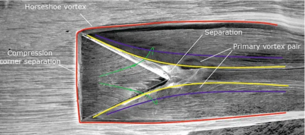
Micro-ramps introduce streamwise vorticity into a flowfield to delay or suppress flow separation. As described by Pitt Ford & Babinsky17, a micro-ramp operates by generating a set of primary and secondary counter-rotating vortex pairs in its wake due to pressure gradients generated along the trailing edges of the device. A pair of horseshoe vortices is also formed at the leading edge of the device as vorticity from the small flow separation induced by flow turning at the leading edge is deflected in the streamwise direction. These wake vortex pairs and leading edge horseshoe vortices are shown in the oil flow visualization of Fig.1. The horseshoe vortices can also be seen to bound a high-shear region downstream of the micro-ramp as evidenced by the darker region corresponding to increased scouring of oil from the surface. A weak oblique shock is generated at the device leading edge, followed by an expansion fan and reattachment shock at the trailing edge. Counter-rotating pairs of secondary vortices originate in small separation regions at the micro-ramp trailing edge, one pair at the corner between the trailing edge and mounting surface and another at the top of the trailing edge where the reattachment shock originates.
The main beneficial product of a micro-ramp is the primary counter-rotating vortex pair which entrains high momentum fluid in the near-wall region. This energizes the boundary layer by giving it a fuller, or healthier, velocity profile for a distance downstream of the device that scales approximately with the device height. Eventually, the vortex cores lift themselves up and out of the boundary layer due to mutually-induced upward velocity, thereby reducing their effectiveness and impact on the boundary layer.
D. Motivation and Objectives
The intent of this work was to investigate the performance and benefits of micro-ramp vortex generators in a low-boom, supersonic inlet and determine the optimal flow control configuration for planned wind tunnel tests of a scale model inlet. Flowfield properties including separation downstream of the shock, boundary layer thickness and radial distortion, both at the AIP were determined to be primary indicators of flow control performance. As long as performance gains are achievable with negligible drag increase (and possibly increased shock stability), the overall
advantage of such flow control could be highly significant. Even if these devices do not eliminate the need for performance-bleed, they may reduce the mass flow rate requirements which would improve overall inlet efficiency.
Starting with the baseline configuration proposed by Anderson et al.15, the parameters of micro-ramp height, distance from the shock, and spanwise array spacing were investigated herein using a Design of Experiments (DOE) approach. Micro-ramp placement in the supersonic flowfield upstream of the terminating normal shock as well as within the subsonic diffuser flow was investigated.
E. Previous Micro-Ramp Simulations
Simulations of micro-ramps in internal supersonic flow, with and without oblique shocks, were previously conducted by the author18 and served to validate much of the methodology employed in the present work. In this previous work, the RANS numerical simulations were based on, and validated with, experimental work performed at the University of Cambridge by Pitt Ford & Babinsky17. This experimental setup consisted of a blow-down supersonic wind tunnel with a rectangular test section 0.09 m high and 0.11 m wide. A pivoting wedge, with leading edge located at the test section inflow plane, was deployed from the wind tunnel top surface to generate oblique shocks at an angle of 7 degrees. This wedge was fully retracted for no shock cases. The no-shock case measurement locations are illustrated in Fig. 2a. For oblique shock cases an additional measurement plane at the shock impingement location of 50 mm was added and spanwise boundary layer velocity profiles were taken at the micro-ramp centerline, half-span, and full-span for all streamwise planes. The oblique shock case measurement locations are illustrated in Fig. 2b.
Flow parameters maintained in the test section during data acquisition runs were Mach number of 2.5, unit Reynolds number of 3x10⁷ m-1, stagnation temperature of 290 K, and stagnation pressure of 170 kPa. Compressed air storage limited run time to around 45 seconds. Variations in Reynolds number over the course of a typical run were less than five percent17.
Micro-ramp vortex generators were based on the geometry proposed by Anderson et al.15, with geometric parameters of chord (c), spanwise array spacing (s) – both normalized by the ramp height (h) – and ramp half-angle (Ap). Standard values of these parameters are 7.2, 7.5, and 24 degrees, respectively. The micro-ramp heights used for the Cambridge experiment were 25%, 38%, 50%, and 75% of the boundary layer thickness, , at the inflow location.
Experimental boundary layer velocity profile measurements were made using a pitot probe traversed by a stepper motor. Additional data were taken using laser doppler anemometry (LDA). Inflow boundary layer properties were measured in a clean tunnel at the -20 mm location, measured from the trailing edge of the micro-ramps. Measurements showed a boundary layer thickness, , of 7.5 mm, displacement thickness, *, of 1.1 mm, momentum thickness, , of 0.8 mm, and a shape factor, H, of 1.3.17 In addition to the inflow properties, boundary layer velocity profiles were measured at downstream stations to investigate micro-ramp performance. In no-shock cases the boundary layer velocity profiles were measured at three streamwise locations downstream of the micro-ramp trailing edge (x=0 mm): 20 mm, 80 mm, and 140 mm. For each plane normal to the flow four boundary layer velocity profiles were taken at spanwise locations corresponding to the micro-ramp centerline, quarter-span, half-span, and full-span.
1. Boundary Layer Velocity Profiles in Oblique Shock Flowfield
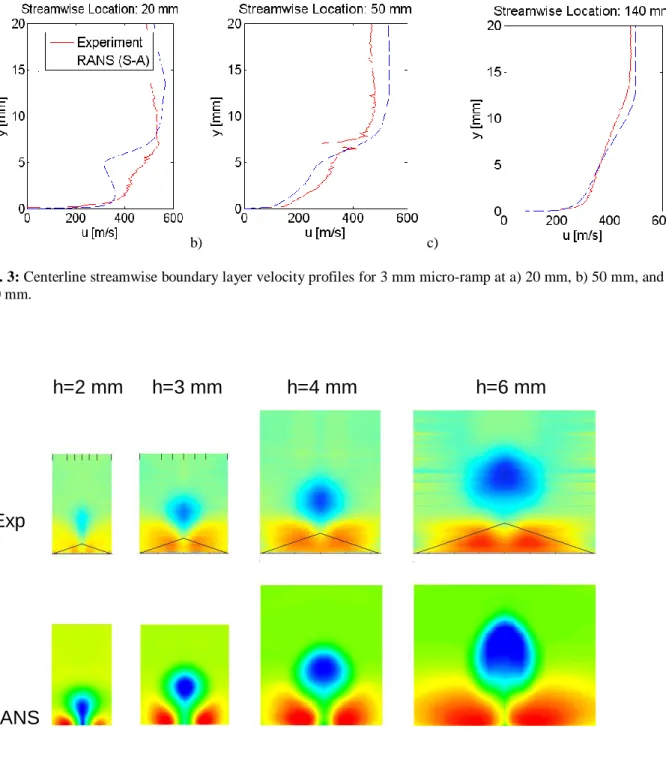
Comparisons of tunnel centerline boundary layer profiles for a 3 mm micro-ramp are shown in Fig. 3. At x = 20 mm the largest deviation from experimental is seen. The numerical prediction in the wake region has an s-shaped profile while the experimental data shows no such feature and a much fuller profile. This indicates that RANS is capturing the near-wall region recovery reasonably well but is under-predicting the wake dissipation.
The next streamwise measurement station is at 50 mm where the oblique shock impinges on the boundary layer. The fuller boundary layer velocity profile above 6 mm from the wall is outside of the shock/boundary layer interaction region whereas the less full profile below is caused by the marked increase in boundary layer thickness and separation bubble caused by shock impingement. This in turn results in a larger local displacement thickness and increased flow velocity above the separation bubble. With increasing streamwise distance the agreement at 140 mm is improved, though with a more exaggerated wake.
2. Parametric Study of Micro-ramp Height in No Shock Flowfield
In order to ascertain the capability of RANS simulations to predict trends in micro-ramp performance, the experimental parametric study of micro-ramp height was replicated. Single ramps of 2 mm, 3 mm, 4 mm, and 6 mm heights were tested in a clean tunnel, no shock configuration. For this comparison, axial velocity contours on planes perpendicular to the flow direction were considered. Upon subtracting the inflow axial velocity distribution from each streamwise plane, regions of low and high momentum can be more easily identified. Use of cross-stream planes where experimental measurements were made also allows for direct comparison with experimental results
processed in the same way. The resulting minimum and maximum velocities at each streamwise location were consistent between experimental and numerical data. Color maps matching the experimental results as closely as possible were chosen. Blue regions correspond to low momentum, including reverse flow, and red regions correspond to high momentum. The results are shown in Fig. 4, where experimental and numerical cross-stream axial velocity contour planes at the 140 mm location are shown for all four micro-ramp heights. Qualitative agreement between the axial velocity contours is good. Both sets of results indicate that mixing of the high momentum fluid entrained near the wall is strongest for the larger device sizes, indicating that the streamwise vortices are still dominant for this location. However, the predictions tend to show a stronger effect of the streamwise vortices near the lower wall than seen in the measurements. This is particularly true for the 2 mm micro-ramp, and indicates that some of the high energy mixing may not be well predicted. Consistent with this shortcoming, the distinct outlines of high and low momentum regions in the numerical results are an indication of incomplete mixing as compared to the experimental results.
Overall, it appears that flow development scales almost linearly with micro-ramp size, so that the flow features are qualitatively similar for all device sizes. This observation is consistent with the findings of Pitt Ford & Babinsky17, who found that the location of the approximate center of the low momentum region plotted as a function of streamwise distance collapses to a line when non-dimensionalized by the micro-ramp height. Furthermore, it follows that smaller devices produce weaker vorticity, though act on fluid closer to the wall. This suggests that the flow features should scale according to downstream distance normalized by device height.
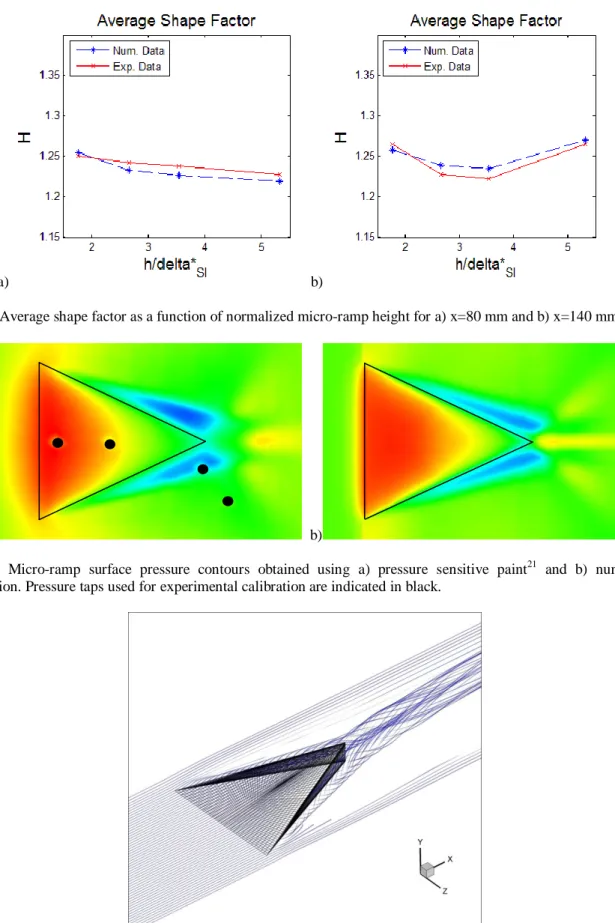
Trends in micro-ramp flowfields for devices of varying size can also be compared by computing the shape factor, which is an indication of boundary layer health, or fullness of the velocity profile. Averaged shape factor, as a function of micro-ramp size, is shown in Fig. 5 for both experimental and numerical data indicating good agreement. For the two streamwise locations considered, 80 mm and 140 mm, the average of values for all spanwise positions was taken, resulting in a single data point. Micro-ramp height was non-dimensionalized by the displacement thickness at the streamwise location corresponding to oblique shock impingement, *SI. This location was used as a reference since the shock-generating wedge and resulting oblique shock were not present for the parametric study of micro-ramp height.
Although the performance of micro-ramps is difficult to gauge in a no-shock configuration it is nonetheless possible to compare the degree to which the expected benefits of improved boundary health are imparted upon the flow. At the farthest downstream station of Fig. 5 (x=140 mm) the greatest decrease in shape factor, and therefore the fullest resulting boundary layer velocity profile, occurs for ramp sizes in the 3-4 mm range which are about 38-50% of the boundary layer thickness. This is consistent with the conclusions reached by Lin19 in a review of micro-VG research indicating that device heights of approximately 40% are optimal, and consistent with the ranges specified in an independent study by McCormick20. Smaller devices produce weak vortex filaments which dissipate quickly, while larger ones produce structures which, although able to persist in the flow longer, act farther away from the wall. The optimal size is between these two extremes.
3. Additional Micro-Ramp Flowfield Visualization
Numerical simulations can be used to better understand the flowfield features. One such example is the micro-ramp surface pressure distribution. Even though surface pressure measurements were not available in the Cambridge data set, a qualitative comparison was made with the pressure sensitive paint (PSP) results of Elliott21 for a similar configuration. The two surface pressure maps are shown in Fig. 6. There is a good qualitative correlation between features in the two flowfields, both indicating that the peak pressure occurs at the leading edge and then decays downstream along the ramp centerline, while the spillover of vortices leads to low pressure regions on the sides of the device. Additionally, since velocity data are available for all nodes in the numerical solution, it is also possible to visualize the primary vortex pair directly using flow streaklines in the near-wall region. Results for this flow visualization method for y+=10 in the micro-ramp region are shown in Fig. 7, where the primary vortex pair can be seen to originate as flow spills around the device sides. Once formed, the vortex filaments can be seen to twist around each other, though this effect is reduced farther downstream as the core vorticity diffuses and dissipates.
II. Methodology A. Inlet and flowfield specifications
The axisymmetric low-boom inlet considered herein is a 12-inch diameter scale model of the full geometry, intended for supersonic wind tunnel testing in the 8’x6’ wind tunnel at NASA Glenn Research Center. Inflow properties were specified to be consistent with wind tunnel test conditions: Mach number of 1.67, stagnation pressure of 4.637 psi, stagnation temperature of 390.8°R, and outflow pressure for the diffuser specified to be
consistent with massflow plug settings to be used in the test. A rendering of the inlet model, with notional upstream micro-ramp array indicated in yellow, is shown in Fig. 8.
B. Grid generation and chimera grid methods
All computational meshes employed in this study were generated using Gridgen V15. Structured grids were used in order to fully resolve boundary layers and capture the flow features associated with micro-VGs. Stretching factors were specified to ensure nodal distributions capable of fully resolving the viscous sub-layer by setting the first grid point away from the wall to coincide with y+~1 for the flow. Node clustering was also utilized to improve resolution in the inlet terminating normal shock region. While multi-zone grids were required for parallel computation, the zonal boundaries were chosen so as to avoid shock/zonal boundary interactions.
Although multi-zone abutting grids are well suited to simple geometries of micro-VGs at a fixed position and mounted to a flat surface such as in a wind tunnel, it was found that grid generation for more complex geometries was expedited by the use of chimera, or overset, grids. Specifically, use of micro-VG grids into an inlet parent grid allowed for easy modification of micro-VG parameters such as height, distance from the inlet throat, and radial array spacing.
Several methods for “mounting” micro-ramps onto the curved centerbody were investigated, including mating at the ramp center-line, mating at the ramp tips, and projecting the ramp geometry onto the centerbody resulting in a curved micro-ramp. The first method required that a pedestal be constructed beneath the ramp to ensure no gaps between it and the surface. This pedestal would alter the micro-ramp flowfield and could cause a stronger leading shock. The second method required that the ramp height be reduced and a concave cut be made in its lower surface, resulting in an alteration of the ramp scaling relations and a possible expansion fan at its leading edge. The last method required no pedestal or scaling modification, and allowed for smooth contact between the ramp surface and inlet center body. This method was chosen for chimera grid generation. The chimera, or overset grid, method was first validated using a micro-ramp on the relatively simple flat surface geometry of the Cambridge experimental cases. In this approach, a micro-ramp grid was inserted into a cutout generated in a larger parent grid of the relevant geometry. An overlap boundary condition was then generated at the interface and coupling was specified at the upstream, downstream, side, and top faces of the inserted block. The micro-ramp and adjacent bottom face surfaces were set as outer boundaries with viscous wall boundary conditions. The same general approach was used for the curved centerbody of the inlet but with the added step of projecting the inserted block to the centerbody surface (Fig. 9). Matching grid resolution within a predefined region of the parent grid enabled generation of the overlap boundary conditions, fringe regions, and inter-zonal coupling using scripts for the WIND-US utility GMAN.
C. Numerical methodology
1. Numerical Schemes
All simulations conducted in the course of this work were performed using the WIND-US computational platform developed by the NPARC alliance, a partnership between the Arnold Engineering Development Center (AEDC) and NASA Glenn Research Center (GRC) with contributions to the improvement and ongoing development of the code provided by the Boeing Company. The WIND-US package supports the solution of the Euler and Navier-Stokes equations of fluid mechanics and allows modeling of turbulent and reacting flows22. In addition to the solver module a number of utilities for grid and solution file manipulation and processing, diagnostics, convergence monitoring, and parallel processing are also available.
Various spatial-discretization schemes, time-integration schemes, and CFL numbers were investigated to determine an appropriate numerical approach. Two-dimensional grids together with the WIND-US axisymmetric keyword, which creates an axisymmetric domain with specified angle of revolution from a two-dimensional geometry, were used for this study to take advantage of axial symmetry and to decrease the computational expense. Results for the matrix of numerical schemes, time integration schemes, and the CFL numbers were compared by periodically computing the ratios of stagnation pressure at the diffuser outflow to the freestream stagnation pressure and the diffuser outflow massflow rate to the capture area mass flow upstream. Convergence was determined by plotting these ratios as a function of the number of iterations. This method of convergence monitoring was selected following the observation that small changes to the flow field continue even after the L2 norms of the Navier-Stokes solver stabilize. Convergence was defined as stagnation pressure recovery of 0.9693±0.005 and massflow ratio of 0.9267±0.001 based on baseline values obtained from a previous fully converged case.
Time integration schemes used in this study included Gauss-Seidel, Runge-Kutta (3-stage), MacCormack (1st -order MAFk, k=2), and the 2nd-order approximate factorization alternating direction implicit (AF ADI) scheme available in WIND-US. With all other settings held constant (3rd-order upwind-biased Roe, CFL=0.5) the 2nd-order
AF ADI time integration gave the lowest run time necessary for convergence and was therefore used for the remainder of this study.
Numerical schemes tested included all relevant numerical schemes available in WIND-US, including Roe, Roe_over (an implementation of the OVERFLOW version of the Roe scheme), VanLeer, and Rusanov. Both 2nd- and 3rd-order upwind-biased implementations of these schemes were investigated, including a “PHYSICAL” version of the Roe scheme optimized for stretched grids. The 2nd-order AF ADI time integration and CFL number of 0.5 were used for this first part of the numerical scheme study, showing that the Rusanov and VanLeer schemes achieved convergence most rapidly.
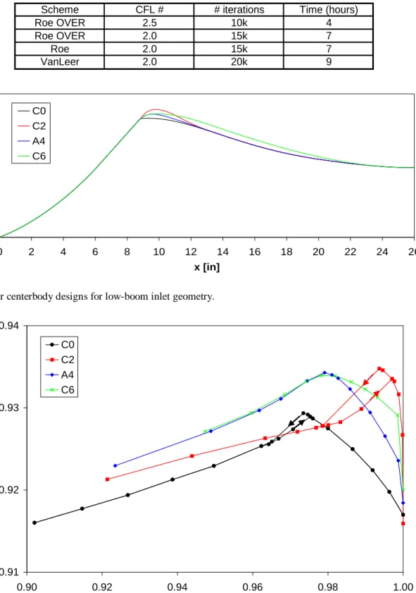
Finally, the CFL number was increased in increments of 0.5 for the best numerical schemes from the previous iteration of the study until an optimal combination of stability and CFL number was found. This corresponded to the 2nd-order upwind-biased Roe_over scheme with a CFL number of 2.5, yielding a speed-up factor of 5.7 compared to the baseline. These four schemes, along with corresponding highest achievable CFL number, number of iterations needed for convergence, and run time, are shown in Table 1. The WIND-US implementation of the OVERFLOW Roe scheme, with a CFL number of 2.5 and 2nd-order AF ADI time integration, was therefore employed in all subsequent simulations. Averaged outflow stagnation pressure values were used to monitor convergence, which was achieved within 15,000 time steps.
For numerical stability in this supersonic flow it was necessary to utilize a total variation diminishing, or TVD, scheme. A study was undertaken to determine TVD limiter performance and to resolve issues of shock over-sharpening, which resulted in horizontal banding downstream of the shock and undulations in stagnation pressure profiles when the default MINMOD TVD limiter was used. All TVD options available in WIND-US for structured grids were tested, including Koren, van Albada, and all relevant values of the compression parameter for the default MINMOD scheme. The Koren limiter was found to yield the best results, without shock over-sharpening as seen with the MINMOD TVD limiter and with smooth stagnation pressure profiles within the diffuser. It was therefore used for all subsequent simulations.
2. BAY Vortex Generator Model
The Bender, Anderson, and Yagle (BAY) vortex generator model was investigated as a possible alternative to the complex and computationally costly resolved vortex generator grids employed for the majority of the present study23. This approach does not require the vortex generator to be explicitly gridded; instead, a body force is applied over a specified range of grid nodes which results in flow turning consistent with that of a flat plate vortex generator at angle of attack. The model has been integrated into WIND-US and validated against experimental and fully resolved computational results for subsonic diffuser flow control with good agreement24.
Model input includes the range of indices in the i, j, and k nodal directions to fully specify the position, the angle of attack (sign can be changed to specify the rotation direction), and vane area. While a number of individual vanes can be specified, it is often helpful to take advantage of symmetry to reduce grid size when vane pairs arrayed around the inlet centerbody are considered. Reflection boundary conditions can be specified when modeling vane pairs with counter-rotating vortices, whereas periodic boundary conditions allow for a co-rotating configuration. Additionally, a model constant can be specified. With a default value of 10.0 for classical vanes this model constant can be adjusted to model alternative vortex generator geometries. While a parametric study of the value of this model constant was undertaken and the value of 1.0 was found to closely approximate results for fully resolved micro-ramps, application of the BAY model was limited to simulation of classical vanes in the subsonic diffuser.
D. Computing environment
1. In-house
A number of single-core and parallel simulations were conducted using in-house quad- and dual quad-core Pentium Xeon 3.0GHz 64-bit workstations with 2GB of DDR2 RAM per core running SUSE Linux 10.0. The parallel processing PVM package available in WIND-US was utilized to perform single-host parallel processing jobs.
2. NCSA
Complex three-dimensional simulations were carried out using the multiple-host parallel processing capabilities of the WIND-US PVM package and NCSA TeraGrid resources. The NCSA Linux cluster Abe (1200 systems of 64-bit Intel Xeon dual-socket quad-core 2.33GHz, 1333MHz system bus, 2GB DDR2 RAM per node, each running Red Hat Enterprise Linux 4) was employed for parallel jobs using up to 64 processors.
III. Inlet Design and History
The baseline low-boom inlet was designed by Tim Conners at Gulfstream Aerospace Corporation (GAC). It has since been analyzed and modified by several researchers using three different CFD codes: Axisymmetric Viscous CFD Solver25 (AVCS), OVERFLOW26, and WIND-US22. In general the codes predicted inlet recoveries within 0.2 points of each other. The modifications have improved the predicted recovery by 0.5 – 1.2 points depending on the operating point, while improving the likelihood that the inlet will be stable. The modifications are described below, where all results were computed with AVCS for consistency.
A. Baseline Inlet
The baseline low-boom inlet, hereafter referred to as C0, was designed using a method of characteristics (MOC) code for the supersonic spike and a polynomial profile for the diffuser. A detailed overview of the design approach and discussion of the compression surface is given by Coyne et al.27. The C0 inlet, shown in Fig. 10 (black), has a slope discontinuity at the shoulder intended to help hold the shock in place. Conners and Don Howe (GAC) analyzed the inlet using the OVERFLOW code, and later Rod Chima at NASA Glenn Research Center (GRC) analyzed it using AVCS. The AVCS results are shown in Fig. 11 (black circles) as a plot of total pressure recovery versus mass flow capture ratio. (The double valued recoveries to the left of the peak will be discussed in section E, Inlet Hysteresis.) It is desirable to operate the inlet near peak recovery at a capture ratio greater than 0.98 to minimize spillage and external shocks that lead to sonic boom. The peak recovery for this design was 0.929, but the recovery dropped off quickly away from the peak and the capture ratio at peak recovery was somewhat low at 0.974.
B. Throat Redesign - Chima Bumps
CFD simulations of the C0 inlet showed large regions of separated flow extending from the slope discontinuity at the shoulder to well downstream in the subsonic diffuser. Chima plotted the separation streamlines at several operating points using the Fieldview CFD visualization software, and used those streamlines to generate a family of rounded shoulder geometries known as the Chima bumps. The largest of these bumps, C2, is shown in Fig. 10 (red). The bump removes the slope discontinuity and moves the throat downstream. The predicted recovery shown in Fig. 11 (red squares) has a peak of 0.935 at a capture ratio of 0.994. These results were significantly better than the C0 baseline.
C. Throat Redesign - Atlanta Bumps
Howe used OVERFLOW to examine a parametric family of shoulder geometries similar to but smaller than Chima’s. He also added a slight curvature to the final supersonic portion of the spike so that supersonic expansion would help turn the flow onto the shoulder. Howe presented his results informally to the design team during the NASA Fundamental Aeronautics meeting in Atlanta, GA. The best of his designs, called A4, is shown in Fig. 10 (blue), and the predicted recovery is shown in Fig. 11 (blue diamonds). The peak recovery of 0.934 at a capture ratio of 0.983 is 0.3 to 0.6 points higher than the baseline everywhere. The A4 geometry is now the standard for conceptual vehicle design at GAC.
D. Diffuser Redesign
With the rounded shoulder designs the fastest area change occurs immediately after the throat, where the flow has just passed through a shock and is close to separation. Chima examined several diffuser designs intended to reduce the rate of diffusion near the throat. The best of these designs, called C6, is shown in Fig. 10 (green), and the predicted recovery is shown in Fig. 11 (green crosses). The peak recovery is the same as for A4, but the recovery is several tenths of a point higher at higher flow rates. The C6 geometry is now the standard for micro-ramp development at the University of Illinois at Urbana-Champaign (UIUC).
E. Inlet Hysteresis
Each operating point on the recovery curves shown in Fig. 11 represents a separate, converged CFD solution. The first calculation for a new design was started from an initial guess, with a low static pressure specified at the exit to produce a choked flow. To improve convergence rates subsequent points were usually restarted from the next point at a higher flow, with a higher static pressure specified at the exit. In this manner the recovery plots were built up from right to left on the cane curve. Howe and Chima both realized that some of the designs were very sensitive to small changes in back pressure near peak efficiency, and Chima noticed that the C0 and C2 designs produced multi-valued solutions, i.e., hysteresis, depending on whether the solution was restarted from a higher or
lower flow. In Fig. 11 the arrows on the C0 and C2 predictions show the direction that the solutions proceed on the two branches of the curves. As the flow ratio decreases from 1.0 the recovery increases to a maximum. At maximum recovery a small increase in exit pressure causes both the flow and recovery to drop abruptly as the shock jumps from the throat to the spike. Increasing the exit pressure further gives stable operating points at lower flows, while decreasing the exit pressure gives stable operating points on the lower branch of the recovery curve.
This hysteresis near peak recovery is better shown in Fig. 12 where inlet static pressure rise is plotted versus mass flow capture ratio. Although exit static pressure is an independent CFD boundary condition and the capture ratio is the dependent variable, pressure rise is plotted on the ordinate for similarity to compressor performance maps. Compressors are generally stable when the slope of the static pressure rise characteristic is negative, and unstable when the slope is zero28. The pressure rise curves for all four inlets have a steep negative slope at high flows, and a lower, linear slope at low flows. However, the C0 and C2 designs have a near-zero slope at peak recovery, suggesting possible instability. In a wind tunnel these designs might behave the same way that they do computationally, with an abrupt drop in flow as the throttle is closed and continuous operation as the throttle is opened, or they could buzz. The A4 and C6 designs have continuous slopes suggesting that these designs will be stable. Thus we have focused on the A4 and C6 designs in this work.
IV. Upstream Micro-VG Studies A. Upstream Micro-Ramp DOE Study
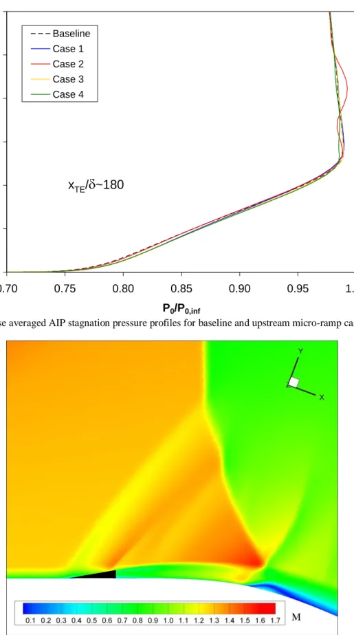
Flow control simulations were first conducted for micro-ramps placed on the inlet spike upstream of the shock. Mach number contours for an axisymmetric slice containing one micro-ramp, representative of all cases considered in the upstream micro-ramp study, are shown in Fig. 13. In order to investigate and optimize the performance of micro-ramps upstream of the shock for the A4 inlet, a main-effects DOE study with three parameters and two values of each was conducted. The design space parameters considered were nondimensional micro-ramp height, h/ where is the local boundary layer thickness, distance from the shock (at peak recovery conditions) with distance measured between the shock and the micro-ramp trailing edge, (xS-xTE)/h, and spanwise array spacing, s/h. The latter two parameters are both nondimensionalized by the micro-ramp height. These parameters form the three axes of the design space, bounded by values of 0.2 to 0.5 for h/ , 5 to 20 for (xS-xTE)/h, and 7.5 to 11.25 for s/h. These parameters and ranges were chosen based on the work of Anderson et al.15 and Pitt Ford & Babinsky17. Four corner points of the design-space cube are required to compute the main-effects dependence. Parameter values for DOE cases 1-4 are specified within Fig. 14, which also shows the streamwise location and height of the micro-ramps corresponding to these four cases overlaid on a centerline cross-section of Mach number contours for the baseline inlet flow.
Profiles of spanwise-averaged stagnation pressure normalized by the freestream stagnation pressure, as a function of distance from the centerbody surface at the AIP, were the first flow parameter considered. The variation of these stagnation pressure profiles was found to be minimal, as indicated in Fig. 15. This can be attributed to vortex dissipation which occurs through the shock and within the diffuser. The effect may exacerbated by excessive dissipation caused by the RANS approach. Distance between the micro-ramp and the data acquisition plane is around 180 local boundary layer thicknesses, a factor of ten more than the longest distance in the previous RANS validation using Cambridge experimental data17. The slight changes in stagnation pressure above the boundary layer are due to shock smearing, interaction of the oblique shock originating at the micro-ramp leading edge and the inlet terminating normal shock, as illustrated in Fig. 16, which is a localized and relatively weak effect.
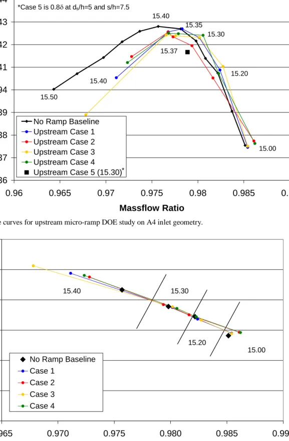
Area averaged AIP values of pressure recovery (stagnation pressure normalized by freestream stagnation pressure) and massflow ratio (ratio of inlet captured massflow to AIP massflow) were calculated, as a function of back pressure, consistent with the range of engine flow requirements and range of inlet operating conditions. These cane curves for the no-ramp baseline and the DOE cases are plotted in Fig. 17. An additional configuration with h/ = 0.8, (xS-xTE)/h = 5, and s/h = 7.5, not contained within the original design space definition, was also simulated at near peak recovery conditions to investigate the effects of micro-ramp height on the order of the boundary layer thickness. The cane curves for cases 1 through 4 all deviate from the baseline no-ramp result for a back pressure of 15.40 psi which corresponds to peak recovery for the baseline case. This is caused by movement of the shock, which is drawn upstream by the presence of the micro-ramp and affected by its interaction with the micro-ramp shock structure. The effect is most significant for case 3, where the stable shock position is fully upstream of the micro-ramps. For lower back pressures the agreement between the baseline and DOE results is quite close, with all but case
2 yielding consistently improved performance. The improvements in pressure recovery and massflow ratio, however, are only a fraction of a percent in all cases.
Massflow ratio is a direct measure of flow spillage, which in turn affects the external shock overpressure generated by the inlet. This overpressure was calculated as the difference of the maximum and minimum static pressure across the shock at a radial distance of 0.16 m from the cowl, normalized by the freestream stagnation pressure. This parameter is plotted as a function of massflow ratio for the baseline no-ramp case and four DOE cases in Fig. 18, indicating a nearly linear dependence. Furthermore, external shock overpressure appears insensitive to the presence of micro-ramps and variations in their configuration. This is consistent with the small changes in massflow ratio in the presence of micro-ramps as noted previously.
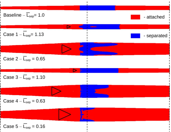
With shock intensity primarily a function of massflow ratio, and the ability of the micro-ramps to significantly affect flowfield parameters at the AIP limited by the streamwise distance and vortex dissipation, local flowfield benefits were investigated. Although the smooth lines of the A4 inlet limit flow separation at massflow rates near peak recovery even without flow control, separation downstream of the shock was found to occur at higher massflow rates. Simulations were therefore conducted at the highest massflow ratio considered in the DOE, 0.985, corresponding to a back pressure of 15.00 psi. Separation area downstream of the shock was compared for the baseline and micro-ramp cases by use of contour plots of velocity at the first grid point away from the wall, proportional to wall shear, as illustrated in Fig. 19, where red areas correspond to streamwise flow and blue areas to reverse flow. Because of the variation in angle of revolution for the grids used in these cases, as dictated by the ramp size and spacing, and due to the symmetric but irregular shape of the separation region with micro-ramps present, it was necessary to consider an average separation length, Lsep. This was computed by dividing the total separation area by the maximum spanwise width for the given case, and normalized such that the baseline Lsep was 1.0. A result for case 5, the larger h/ = 0.8 micro-ramp outside of the original DOE design space, is included along with the no-ramp baseline and four corner cases. The smaller h/ = 0.2 micro-ramps of cases 1 and 3 were found to increase separation downstream of the shock slightly, with Lsepof 1.13 and 1.10. This also indicated a very weak dependence on distance from the shock and array spacing. The larger h/ = 0.5 micro-ramps of cases 2 and 4 resulted in Lsepvalues of 0.65 and 0.64, respectively, where the effect of distance from the shock and array spacing appear minimal. Finally, the h/ = 0.8 micro-ramp of case 5 reduced Lsepto 0.16, with separation occurring only at the shock location itself and along the domain edges, or in the gap between micro-ramps where the vortices have the weakest effect.
Due to the large variation seen inLsep, and significant effect of micro-ramps on this aspect of the flowfield, it was chosen as the response function for the DOE analysis. Additionally, the relative contributions of the three parameters h/ , (xS-xTE)/h, and s/h were computed to be 63%, 24% and 3%, respectively. It was therefore decided to neglect the array spacing parameter s/h and analyze the data in two dimensions. The result is shown in Fig. 20, where micro-ramp height is seen to have the largest effect on flow separation. Distance from the shock at which the micro-ramps are placed is a second-order effect. This analysis indicated that larger values of h/ yield reduced separation area. In order to investigate behavior in the limit of large devices, an additional h/ = 1.1 micro-ramp was tested for comparison with Case 5. The resulting Lsep value of 0.17 indicates only a modest drop-off in separation control. However, it is likely that additional benefits for ramp heights beyond those on the order of the boundary layer thickness would be offset by increases in blockage, device wave drag, and vortex dissipation.
B. Alternative Micro-VG Geometry Study
In addition to the standard micro-ramps two additional geometries were tested: the split-ramp and ramped-vane, illustrated in Fig. 21. Both designs aim to decrease blockage caused by the presence of the device, thereby diminishing the wake and reducing overall device drag, while generating counter-rotating vortex pairs similar to those of the standard micro-ramp. This is achieved by dividing the device into two halves, split and symmetric about the streamwise axis, such that additional flow can pass through the resulting gap. An added benefit of this gap is increased spacing between the vortex filaments formed by the device, weakening their interaction. This weaker interaction reduces the amount of inter-vortex upwash and helps maintain the vortex cores near the wall longer, increasing their ability to transfer high momentum fluid into the boundary layer.
Both geometries were simulated using the A4 inlet and at the same high-massflow conditions as the separation area study in the preceding section. The device height was fixed at the value previously found to yield minimum
separation area, h/ = 0.8. Lsep was computed for both cases, yielding values of 0.16 and 0.06 for the ramped-vane and split-ramp, respectively. Thus, the ramped-vane is seen to perform equally well as the standard h/ = 0.8 micro-ramp of Case 5, whereas an additional decrease in post-shock separation is achieved with the split-micro-ramp geometry. Separation area for these two cases is illustrated in Fig. 22, compared to the baseline flow and Case 5 of the upstream DOE. While the separation structure downstream of the ramped-vane is qualitatively very similar to that of the micro-ramp, that downstream of the split-ramp differs significantly with two fully attached channels coincident with the vortex filaments and separated flow only downstream of the center and outside edges of the device. With the exception of a slight localized increased in AIP stagnation pressure due to shock smearing, as noted for the larger micro-ramps of the upstream DOE, the alternative geometries did not significantly affect the shape factor, distortion, or introduce spanwise variation at the AIP.
V. Downstream Micro-VG Studies A. Downstream Micro-Ramp DOE Study
Micro-ramp placement within the subsonic diffuser was also investigated. With no shock/boundary layer interaction or shock-induced flow separation to control, the primary benefit to the subsonic flow is that of reduced distortion. As in the upstream study, a DOE design space was defined. However, the parameter with the weakest influence, s/h, was not included and the resulting design space was therefore two-dimensional with only h/ and dimensional distance from the inlet geometric throat to the micro-ramp leading edge considered. The change to a dimensional distance parameter and a fixed geometric reference (instead of the shock position) was made to allow for consistent micro-ramp leading edge placement within the diffuser and purely geometric definition, as dictated by model design and machining constraints. The design space was bounded by 0.35 and 1.0 for h/ , and by 15.7 and 85.7 mm for the micro-ramp leading edge to geometric throat distance. Interior values were subsequently added to improve the response surface resolution. This two-dimensional design space and the six cases considered are indicated in Fig. 23. Additionally, Fig. 24 shows the streamwise location and height of the micro-ramps corresponding to these six cases overlaid on a centerline cross-section of Mach number contours for the baseline inlet flow.
The presence of downstream micro-ramps was found to cause significant radial and spanwise variation in the flow. The spanwise nature of these variations relative to the micro-ramp can be seen in the Mach number contours of Fig. 25, for the centerline and full-span planes, relative to the micro-ramp, of DOE case 4. A wake region can be distinctly seen downstream of the micro-ramp centerline and a much thinner boundary layer is present in the gap region. Additionally, spanwise stagnation pressure contours at the cross-stream AIP plane are also shown in Fig. 26, where the micro-ramp wake and low-momentum region being lifted away from the centerbody surface is clearly visible, as are regions energized by transfer of high-momentum fluid to the near-wall region at the micro-ramp half-span. Boundary layer rake pitot probe locations as defined by SAE ARP1420B Gas Turbine Engine Inlet Flow Distortion Guidelines, with probes on each rake located at the centroids of equal areas, are shown for reference29. Relevant boundary layer features are seen to fall below the first probe position, indicating that experimental flow measurements would need to be performed using additional probes.
A quantitative comparison of AIP stagnation pressure profiles, normalized by freestream stagnation pressure, for discrete locations defined by the micro-ramp centerline, half-span, and full-span, compared to the no-ramp baseline, are shown in Fig. 27. The centerline profile shows the effect of the micro-ramp wake, with low momentum flow being lifted away from the wall. The profile is fullest at the half-span, corresponding to the vortex core position and where the maximum amount of high-momentum flow is entrained in the near-wall region. At the full-span position, in the gap between adjacent micro-ramps in the array, the profile is still significantly fuller than the no-ramp baseline.
Due to these spanwise variations in AIP stagnation pressure, it was necessary to use spanwise averages to compare between baseline and DOE cases, yielding a single profile which captures the net contribution of a given micro-ramp to the flowfield. Spanwise averaged stagnation pressure profiles, normalized by the freestream stagnation pressure, for the baseline inlet and the six DOE cases are shown in Fig. 28. It can be seen that all cases yield a fuller boundary layer profile in the near wall region relative to the baseline, however, this effect is most pronounced for the large h/ = 1.0 cases 4 and 6. A corresponding decrease in pressure recovery in the outer portion of the boundary layer is noted, again most pronounced for cases 4 and 6, and clearly indicates that high momentum fluid is transported from the outer flow to the near-wall region resulting in a fuller profile. A single parameter to quantify the performance of these six cases was found in the form of incompressible axisymmetric shape factor, H, the ratio of displacement and momentum thicknesses, which is highly sensitive to changes in the boundary layer
velocity profile. Low values of shape factor are desirable as they indicate a healthy boundary layer with a full profile and low radial distortion. Values of shape factor for the baseline and micro-ramp cases are also summarized within Fig. 28. Used as a DOE response function, shape factor values can also be used to map the design space as a function of h/ and distance from the geometric throat, as indicated in Fig. 29. The primary dependence is again on micro-ramp height, however, the effect of position is much more significant than in the upstream study. The general trend is that increased micro-ramp size and increased distance from the geometric throat, i.e. placement closer to the AIP, result in lowest values of shape factor.
As in the upstream study, cane curves for each case and for range of back pressure conditions were generated for comparison with the baseline no-ramp case. These cane curves are displayed in Fig. 30. The impact of micro-ramps on the flow is more pronounced than in the upstream study, with improvement in pressure recovery of more than a quarter percent and in massflow ratio of greater than a tenth of a percent. There is also a clear difference in the performance of larger micro-ramp in cases 2 and 4-6, which yield consistently improved performance for all massflow rates above peak recovery, whereas smaller values of h/ yield cane curves which cross the baseline only for the highest massflow rates.
B. Downstream NACA 0012 Vane Study
Since it was found that micro-ramps on the order of the boundary layer thickness perform best in the subsonic diffuser, and because at this scale the devices are no longer micro- but rather traditional full-scale VG’s, the effectiveness of conventional vanes was investigated. These vanes were simulated in the subsonic diffuser using the BAY vortex generator model described in section C.2. The geometry specified was qualitatively similar to the outer edges of a corresponding micro-ramp, and vanes were considered in pairs to generate counter-rotating vortices similar to those produced by micro-ramps. Vane incidence angle was fixed at 16 degrees. Three parameters including height, distance downstream from the geometric throat, and spanwise array spacing, with ranges of 0.4 to 1.0 for h/ , 2 to 6 inches for geometric throat distance, and 1.0 to 4.0 for s/h. For the vane geometry the value of s/h corresponds to the spanwise spacing between leading and trailing edges of adjacent vanes. A typical vane pair is illustrated in Fig. 31. Using the symmetry argument of section C.2, only one vane was specified in the model and reflection boundary conditions were used to model the circumferential array.
Simulations of four vane configurations based on these ranges were initially performed using the C6 inlet geometry and the design massflow ratio of 0.988, corresponding to a back pressure of 15.00 psi. Stagnation pressure contours at the AIP plane for the baseline flow and these four cases are shown in Fig. 32, along with the case parameter specifications. All configurations transport high-momentum fluid to the near-wall region and introduce three-dimensionality not present in the baseline case. The largest devices do this to the largest extent and also generate more upwash and a larger wake region. To evaluate the effect on radial distortion, spanwise averages of stagnation pressure at the AIP were taken and compared with the baseline flow. These profiles, along with corresponding values of axisymmetric shape factor, are shown in Fig. 33. A pronounced wake is again evident and is most pronounced for the large devices. It is also with the largest devices that the fullest near-wall boundary layer profiles and lowest values of axisymmetric shape factor are obtained. The largest decrease from the baseline flow value of 1.44 is achieved by Case 4, down to 1.08. Data for the four vane cases and baseline were also used as inflow for fan simulations performed by Jeremy Hughes and Jason Jacobs at Rolls-Royce Indianapolis, indicating that Case 4 offers the best fan performance. This finding is consistent with the low value of axisymmetric shape factor and flow distortion found for Case 4, confirming the validity of these ranking criteria.
Finally, the specifications of the vanes in Case 4 were translated to the A4 inlet and simulated at the design massflow ratio of 0.988. To gain additional insight into the flowfield two configurations were considered: one with counter-rotating and one with co-rotating vortices. The counter-rotating configuration, analogous to Case 4 in the C6 inlet vane study, performed similarly to the previous result. The axisymmetric shape factor was reduced from a baseline value of 1.39 to 1.11, the profile near the wall became significantly fuller, and a pronounced wake was again present. In the co-rotating case, however, almost no deviation from the baseline was observed. The vortices mix and dissipate well upstream of the AIP, resulting in a uniform, almost axisymmetric profile. Flow contours, spanwise averaged AIP stagnation pressure contours, and values of axisymmetric shape factor are summarized in Fig. 34.
VI. Conclusions
The flow control performance of micro-VG’s upstream and downstream of the terminating normal shock of a model scale, low-boom, external compression, axisymmetric inlet was analyzed using RANS simulations. Upstream
micro-VG placement was found to significantly reduce separation area downstream of the terminating normal shock, by up to 96%, and performance was primarily driven by device height. However, the upstream micro-VG’s had minimal effect on overall inlet pressure recovery, massflow ratio, and radial distortion at the AIP. In contrast, downstream micro-VG’s were able to substantially influence the AIP distributions. In particular, the downstream devices yielded fuller AIP boundary layer profiles, a corresponding reduction in incompressible axisymmetric shape factor of up to 0.21, and improvements in pressure recovery and massflow ratio of up to a quarter of a percent and a tenth of a percent, respectively. DOE response function analysis was performed for average separation length for the upstream cases and for incompressible shape factor at the AIP for the downstream cases. Again, micro-VG height, h/ , was found to have the dominant effect on performance in both cases, with larger values of this parameter resulting in improved performance. The effect of array spacing, s/h, was found to be very weak while streamwise position effects were significant but secondary. These results indicate that inlet boundary layer properties can be controlled to a certain extent with the application of VG’s. Effects of unsteadiness, and the impact of micro-ramps on shock stability, could not be investigated due to the limitations of RANS. Large eddy simulation (LES) or detached eddy simulation (DES) could be used in future studies to quantify these effects.
VII. Recommendations
The investigations undertaken in the course of this work indicate that two distinct positive effects can be achieved with the use of vortex generators. Firstly, a reduction of separation area downstream of the terminating normal shock, can be achieved with micro vortex generators placed in supersonic flow on the compression surface upstream of the shock. Secondly, an improvement in boundary layer health, corresponding to a decrease in shape factor and reduced radial distortion at the AIP, can be achieved with vortex generators placed within the subsonic diffuser. The downstream VG placement has no effect on separation area downstream of the shock whereas upstream VG placement results in a small change in outflow properties due to shock smearing.
For the upstream VG’s it was determined that a device height of 0.8 is optimal based on minimizing the extent of post-shock flow separation. With this device height held constant, the most effective geometries in order of effectiveness are the split-ramp, standard micro-ramp, and ramped-vane. Distance from the shock at which the devices are placed was found to have only a weak impact on performance and so a fixed value of 5 is recommended. Similarly, the spanwise array spacing was found to be a secondary effect and the standard spacing values for each geometry are therefore used. Specifications for the best four upstream configurations are summarized in Table 2.
For downstream VG’s the best performance was obtained with standard vanes, however, standard micro-ramps with height scaled to be on the order of the boundary layer thickness were also shown to favorably impact AIP properties. Optimal vane performance was seen for pairs generating counter-rotating vortices similar to those produced by the other vortex generator geometries considered. Device heights between 0.4 and 1.0 were all found to improve the AIP flowfield, with larger devices providing increased benefits. Placement closer to the AIP and increased spanwise separation between vane leading edges were also found to offer performance benefits. Specifications for the best four downstream configurations are summarized in Table 3. In all cases, both upstream and downstream, the devices (either one micro-ramp or the two halves of a split-ramp, ramped-vane, or two adjacent, spanwise-diverging vanes are considered a “device”) are arrayed circumferentially around the inlet centerbody. The total number of devices for each configuration is indicated in Tables 2-3.
Figures
Fig. 1: Oil flow visualization of micro-ramp flowfield with schematic of flow features17.
a)
b)
Fig. 2: a) Schematic of wind tunnel and streamwise data acquisition locations for a) no-shock case and b) oblique shock case17.
a) b) c)
Fig. 3: Centerline streamwise boundary layer velocity profiles for 3 mm micro-ramp at a) 20 mm, b) 50 mm, and c) 140 mm.
Fig. 4: Cross-stream velocity planes at 140 mm for all four micro-ramp heights. Inflow velocity profile is subtracted from all planes.
h=6 mm
h=4 mm
h=3 mm
h=2 mm
RANS
Exp
a) b)
Fig. 5: Average shape factor as a function of normalized micro-ramp height for a) x=80 mm and b) x=140 mm.
a) b)
Fig. 6: Micro-ramp surface pressure contours obtained using a) pressure sensitive paint21 and b) numerical simulation. Pressure taps used for experimental calibration are indicated in black.
Fig. 8: Micro-ramp flow control array on the centerbody of a low-boom inlet geometry.
Fig. 9: Chimera grid approach showing parent inlet grid (black) and inserted micro-ramp block (blue) for the inlet geometry.
Table 1: Number of iterations and time required for convergence of final four schemes investigated at maximum stable CFL number.
Scheme CFL # # iterations Time (hours)
Roe OVER 2.5 10k 4 Roe OVER 2.0 15k 7 Roe 2.0 15k 7 VanLeer 2.0 20k 9 0 1 2 3 0 2 4 6 8 10 12 14 16 18 20 22 24 26 x [in] Y [in] C0 C2 A4 C6
Fig. 10: Four centerbody designs for low-boom inlet geometry.
0.91 0.92 0.93 0.94 0.90 0.92 0.94 0.96 0.98 1.00 Massflow Ratio Pr essure Recover y C0 C2 A4 C6