Operating and
Service Manual
4000TP4G8
Model
10031106
Part Number
Serial Number
EC Declaration of Conformity
We; Amplifier Research
160 School House Road
Souderton, PA 18964
declare that our product;
the Model 4000TP4G8 amplifiers
to which this declaration relates is in compliance with the requirements of the EEC EMC
Directive (89/336/EEC) and Low Voltage Directive (73/23/EEC) in accordance with the
relative standards listed below:
EMC:
EN 50082-1: 1992
Electromagnetic compatibility – Generic immunity standard
EN 50081-1: 1992
Electromagnetic emissions requirements for Industrial, Scientific, and
Medical (ISM) Equipment
Safety:
EN 60950 (1995)
The CE marking is affixed on the device according to the EC Directives.
Donald R. Shepherd
President
INSTRUCTIONS FOR SAFE OPERATION
Revised 0517
Observe the following safety guidelines to help ensure your own personal safety and to help protect your equipment and working environment from potential damage.
INTENDED USE
This equipment is intended for general laboratory use in generating, controlling, and measuring levels of electromagnetic Radio Frequency (RF) energy. Ensure that the device is operated in a location which will control the radiated energy and will not cause injury or violate regulatory levels of electromagnetic interference.
SAFETY SYMBOLS
These symbols may appear in your user manual or on equipment.
This symbol is marked on the equipment when it is necessary for the user to refer to the manual for important safety information.
The caution symbol denotes a potential hazard. Attention must be given to the statement to prevent damage, destruction, or harm.
Dangerous voltages are present. Use extreme care.
Indicates a terminal intended for connection to an external conductor for protection against electrical shock in case of a fault, or the terminal of a protective earth (ground) electrode.
Indicates invisible laser radiation–do not view directly with optical instruments.
Indicates frame or chassis ground connection terminal.
Indicates alternating current.
Indicates this product must not be disposed of with your other household waste.
Indicates that the marked surface and adjacent surfaces can attain temperatures that may be hot to the touch.
EQUIPMENT SETUP PRECAUTIONS
Review the user manual and become familiar with all safety markings and instructions. Protection provided by the equipment may be impaired if used in a manner not specified by AR RF/Microwave Instrumentation (AR).
• Follow all lifting instructions specified in this document. • Place the equipment on a hard, level surface.
• Do not use the equipment in a wet environment, for example, near a sink, or in a wet basement.
• Position your equipment so that the power switch is easily accessible.
• Leave 10.2 cm (4 in) minimum of clearance on all vented sides of the equipment to permit the airflow required for proper ventilation. Do not restrict airflow into the equipment by blocking any vents or air intakes. Restricting airflow can result in damage to the equipment, intermittent shut-downs or safety hazards.
• Keep equipment away from extremely hot or cold temperatures to ensure that it is used within the specified operating range.
• While installing accessories such as antennas, directional couplers and field probes, take care to avoid any exposure to hazardous RF levels.
• Ensure that nothing rests on your equipment’s cables and that the cables are not located where they can be stepped on or tripped over.
• Move equipment with care; ensure that all casters and/or cables are firmly connected to the system. Avoid sudden stops and uneven surfaces.
BEFORE APPLYING POWER
Your AR equipment may have more than one power supply cable. Use only approved power cable(s). If you have not been provided with a power cable for the equipment or for any AC-powered option intended for the equipment, purchase a power cable that is approved for use in your country. The power cable must be rated for the equipment and for the voltage and current marked on the equipment’s electrical ratings label.
Incorrectly installing or using an incompatible line voltage may increase the risk of fire or other hazards. To help prevent electric shock, plug the equipment and peripheral power cables into properly grounded electrical outlets. These cables are equipped with three-prong plugs to help ensure proper grounding. Do not use adapter plugs or remove the grounding prong from a cable.
Do not modify power cables or plugs. Consult a licensed electrician or AR trained service technician for equipment modifications. Always follow your local/national wiring rules.
Do not operate the equipment if there is physical damage, missing hardware, or missing panels.
SAFETY GROUND
This equipment is provided with a protective earth terminal. The mains power source to the equipment must supply an uninterrupted safety ground of sufficient size to attach wiring terminals, power cord, or supplied power cord set. DO NOT USE this equipment if this protection is impaired.
INSTRUCTIONS FOR SAFE OPERATION
Revised 0517
HAZARDOUS RF VOLTAGES
The RF voltages on the center pin of an RF output connector can be hazardous. The RF output connector should be connected to a load before AC power is applied to the equipment. Do not come into contact with the center pin of the RF output connector or accessories connected to it. Place the equipment in a non-operating condition before disconnecting or connecting the load to the RF output connector.
ACOUSTIC LIMITATIONS
If equipment noise exceeds 80dB, ear protection is required. MAINTENANCE CAUTION
Adjustment, maintenance, or repair of the equipment must be performed only by qualified personnel. Hazardous energy may be present while protective covers are removed from the equipment even if disconnected from the power source. Contact may result in personal injury. Replacement fuses are required to be of specific type and current rating.
ENVIRONMENTAL CONDITIONS
Unless otherwise stated on the product specification sheet, this equipment is designed to be safe under the following environmental conditions:
• Indoor use
• Altitude up to 2000m • Temperature of 5°C to 40°C
• Maximum relative humidity 80% for temperatures up to 31°C. Decreasing linearly to 50% at 40°C.
• Main supply voltage fluctuations not to exceed ± 10% of the nominal voltage or minimum and maximum autoranging values.
• Pollution degree 2: Normally non-conductive with occasional condensation. While the equipment will not cause hazardous condition over this environmental range, its performance may vary.
EQUIPMENT CONTAINING LASERS
AR Field Probes (FL/PL Series) and Field Analyzers (FA Series) are Class 1 laser products containing embedded Class 4 lasers. Under normal use, the laser radiation is completely contained within the fiber optic cables and poses no threat of exposure. Safety interlocks ensure that the laser is not activated unless the cables are properly connected. Always exercise caution when using or maintaining laser products. Do not view directly with optical instruments.
RF ANTENNAS
• This equipment (antenna or antenna assembly) may be heavy, requiring two persons to lift. Use caution when installing or removing unit. Follow all equipment setup and lifting instructions specified in this document.
• Ensure connectors are appropriate for intended operation. Connectors are specified in the user manual and product specification sheet.
• Do not exceed the maximum RF input level stated in the specifications. Refer to the user manual and product specification sheet to determine the applicable RF levels. • Excessive RF input could damage the equipment or
connectors, causing safety hazards.
• When in operation, the RF voltages on the antenna elements can be hazardous. Do not come into contact with the antenna or elements when the RF input connector is connected to a live RF source.
• To avoid injury to personnel and accidental damage to power amplifier or antenna, disable the RF output of power amplifier before connecting or disconnecting the input connection to the antenna.
• Perform periodic inspections of antenna and field probe systems to verify calibration due date, proper operation, and overall condition of equipment.
RACK MOUNTED TWT MODELS
Some TWT models are supplied without the removable enclosure offered for benchtop use. These rack-mountable models may be supplied with either carry handles or slides and front handles installed. Follow all lifting instructions specified in this document and installation instructions supplied in the TWT user manual.
LIFTING INSTRUCTIONS FOR AR EQUIPMENT Because most products must be
handled during distribution, assembly and use, the risk of serious injury due to unsafe product handling should be a fundamental consideration of every user. An authoritative guideline for
eliminating unwarranted risk of injury caused by lifting is provided by the NIOSH Work Practices (Publication #94-110) available at:
https://www.cdc.gov/niosh/docs/94-110/pdfs/94-110.pdf. In general, observe the following guidelines for lifting a weight of 50 lb or more:
• Use lifting eye (for floor standing) or side handles (table top) to lift unit only.
• Use equipment of adequate capacity to lift and support unit. • If using forklift to move unit, be sure forks are long enough
to extend beyond the side of the unit.
ADDITIONAL WARNINGS & NOTES
WARNING:This equipment generates high voltages and high power Radio Frequency energy.
Please read and follow the instructions for safe operation of this unit.
WARNING:
This equipment operates at potentially lethal voltages. Only trained, qualified personnel should operate, maintain, or service it.
Hazardous energy may be present while protective covers are removed from the equipment even if disconnected from the power source. Contact may result in personal injury.
CAUTION:
Adjustment, maintenance, or repair of the equipment must be performed only by qualified personnel.
CAUTION:
Replacement fuses are required to be of specific type and current rating.
CAUTION:
The information in this document was obtained from reliable sources and was believed to be accurate at the time of publication. Since subsequent modifications to the machine may have been made, use this information only as a guide. Carefully compare the unit's actual configuration and operation to the descriptions in this manual before you undertake to operate, service, or modify this machine. Any variance or modification should be noted, dated, and initialed in the discrepant part of all manuals on hand for future reference. If you have technical or editorial comments you wish to make to the manufacturer, please write them on photocopies of the relevant sheets.
NOTE: The contents of this document are the property of the manufacturer and this document is delivered on the express condition that it not be disclosed, reproduced in whole or in part, or used for manufacture for anyone other than the manufacturer without its written consent, and that no right is granted to disclose or so use any information in this document.
Suggested Periodic Maintenance for TWT Amplifiers
1.
Keep monthly log of the voltages, currents and temperatures as shown on Menus. Also record
Date, “Console” and “Operate” hours. Take readings in Operate mode with the gain at zero
(0%) percent. Leave unit in Operate mode for 20 minutes (Max Duty if Pulsed Unit), and then
record data. Review the log to identify trends and contact factory if required.
2.
Keep monthly log of performance with active RF. At mid-band frequency, with Gain set to
100%, apply RF drive that will provide rated power. This will help indicate if the gain or power
is changing and if the traveling wave tube or pre-amp needs service. Record the following:
a.
RF Drive Level
b.
Forward Power
c.
Reverse Power
d.
Body Current (Iw)
e.
Sample Port Power reading (if possible).
3.
Remove air intake filter and clean using compressed air and/or vacuum cleaner.
4.
Ensure air inlet and outlet are unobstructed.
5.
Check that AC Input connections are secure. Make sure the AC cable is not damaged or
deteriorated.
6.
Check that both input and output RF connections (waveguide or coax) are connected tightly and
un-damaged.
CONTENTS
CONTENTS ... 1
1. DESCRIPTION AND SPECIFICATIONS ... 1
1.1 General ... 1
1.2 TWTA Description ... 1
1.3 Suggested Applications ... 1
1.4 Specifications ... 1
1.5 Test Data Sheet ... 1
2. THEORY OF OPERATION ... 3
2.1 Design of the Amplifier ... 3
2.2 Description of the RF Subsystem ... 3
2.3 Description of the Power Supply Subsystem ... 3
3. OPERATION ... 5
3.1 Warnings and Cautions ... 5
3.2 Installation ... 6
3.2.1 Unpacking ... 6
3.2.2 Mounting ... 7
3.2.3 Cooling Requirements ... 7
3.2.4 AC Line Power Connections ... 8
3.2.5 RF Connections... 8
3.3 Front Panel Features ... 9
3.3 Rear Panel Features ... 10
3.5 Front Panel and Soft Keys ... 10
3.5.1 Overview ... 10 3.5.2 Menu Screens ... 13 3.5.3 Setup Screens ... 13 3.5.4 Sleep Mode ... 14 3.5.5 Warning Screens ... 14 3.5.6 Miscellaneous Screens ... 15
3.6 Initial Turn On and Warm-up Procedure ... 16
3.8 RF Operation ... 17
4. MAINTENANCE ... 19
4.1 Safety Warnings and Cautions ... 19
4.2 Unauthorized Repairs ... 19
4.3 Preventive Maintenance ... 19
4.4 Troubleshooting ... 20
4.5 Non-Repairable Modules ... 21
4.6 Recommended Spare Parts ... 21
5. TECHNICAL DOCUMENTATION ... 23
5.1 Top Level Build Tree (see Appendix C) ... 25
5.1.1 A38004-100 Pulsed HPA ... 25
5.2 Schematics ... 27
Model 4000TP2G8
2 Rev A
5.3.1 HPA Logic and Control Board (A23050-085) ... 30
5.3.2 HPA Interface Board (A25444-001) ... 32
Appendix A Remote RS422/485 Computer Interface ... 35
Interface Capabilities ... 35
Implementation ... 35
Hardware Configuration Using Setup Screen 7 ... 35
FIGURES 3-1 Front Panel ... 9
3-2 Rear Panel ... 10
3-3 Soft Key Display ... 11
3-4 Menu Map ... 12
TABLES 3-1 Front Panel Features ... 9
3-2 Rear Panel Features ... 10
Rev A 1
1. DESCRIPTION AND SPECIFICATIONS
1.1 GENERAL
This manual provides operating, interfacing and selected service information pertinent to the AR Model 4000TP4G8 Broadband Microwave amplifier. The Model 4000TP4G8 is a pulsed 4,000 watt L-band traveling wave tube amplifier (TWTA).
1.2 TWTA DESCRIPTION
The amplifier uses a 4,000 watt traveling wave tube (TWT) to provide 4,000 watts minimum output over the TWT amplifier's full bandwidth, higher in other parts of the band. The amplifier is well suited for applications where instantaneous bandwidth and high gain are required. The amplifier is completely self-contained and packaged for standard 19-inch rack mounting.
Primary power is 190-260 volts 50-60 Hz, single phase. An efficient switching power supply design provides minimum power consumption. A fast regulation control loop and a high degree of filtering ensure performance within specifications over a wide range of operating conditions. The amplifier is fully enclosed, and the upper and lower panels of the rack mountable amplifier are interlocked to reduce the likelihood of accidental contact with high voltage.
1.3 SUGGESTED APPLICATIONS
This equipment is intended for general laboratory environments. It is designed to be used in the process of generating, controlling and measuring high levels of electromagnetic Radio Frequency (RF) energy. Therefore the output must be connected to an appropriate load such as an antenna or field generating device. It is the responsibility of the user to assure the device is operated in a location which will control the radiated energy such that it will not cause injury and will not violate regulatory levels of electromagnetic interference.
1.4 SPECIFICATIONS
Refer to the AR data sheet at the end of this section for detailed specifications.
1.5 TEST DATA SHEET
Test Data for a specific unit is prepared at the time of manufacture and is included with the unit's copy of this manual.
Model 4000TP2G8
temperature and cabinet temperature. Modu-lar design of the power supply and RF compo-nents allow for easy access and repair. Use of switching mode power supplies results in sig-nificant weight reduction.
Housed in a stylish contemporary cabinet, the amplifier provides readily available pulsed RF power for a variety of applications in Test and Measurement, (including EMC RF pulse sus-ceptibility testing), Industrial and University Research and Development, and Service appli-cations. AR also offers a broad range of am-plifiers for CW (Continuous Wave) applica-tions.
See Model Configurations for alternative prime power, packaging, and special features. The export classification for this equipment is 3A999.d. These commodities, technology or software are controlled for export in accord-ance with the U.S. Export Administration Regu-lations. Diversion contrary to U.S. law is pro-hibited.
The Model 4000TP4G8 is a self-contained, forced air cooled, broadband traveling wave tube (TWT) microwave amplifier designed for pulse applications at low to moderate duty factors where instantaneous bandwidth and high gain are required. A reliable TWT pro-vides a conservative 3800 watts minimum peak RF pulse power at the amplifier output connector. Stated power specifications are at the fundamental frequency.
The amplifier’s front panel digital display shows forward and reflected average power output or forward and reflected peak power, plus extensive system status information ac-cessed through a series of menus via soft keys. Status indicators include power on, warm-up, standby, operate, faults, excess average or peak reflected power warning and remote. Standard features include a built-in IEEE-488 (GPIB) interface, 0dBm input, TTL Gating, VSWR protection, gain control, RF output sam-ple port, auto sleep, plus monitoring of TWT helix current, cathode voltage, collector volt-age, heater current, heater voltvolt-age, baseplate
Features
Specifications4000TP4G8
Pulse Amplifier M1–M11, M24 4000 Watts 4GHz–8GHz AR RF/Microwave Instrumentation 160 School House Rd Souderton, PA 18964 215-723-8181 For an applications engi-neer call:800.933.8181POWER (Fundamental), Peak Pulse, @ Output: Nomi-nal: 5000 watts; Minimum: 3.8 kW from 4-4.5 GHz 4.0 kW from 4.5-7.5 GHz 3.8 kW from 7.5-8.0 GHz FLATNESS: ±10 dB maximum FREQUENCY RESPONSE: 4-8 GHz
INPUT FOR RATED OUTPUT: 1.0 milliwatt maximum GAIN (at maximum setting): 66 dB minimum GAIN ADJUSTMENT (continuous range): 35 dB mini-mum
INPUT IMPEDANCE: 50 ohms, VSWR 2.5:1 maximum OUTPUT IMPEDANCE: 50 ohms, VSWR 2.5:1 typical MISMATCH TOLERANCE: Output pulse width foldback protection at peak reflected power exceeding 1000 watts. Will operate without damage with any magni-tude and phase of source and load impedance. May oscillate with unshielded open due to coupling to in-put. Should not be tested with connector off. See S3M special option, if applicable.
PULSE CAPABILITY:
Pulse Width 0.07 – 50 microseconds. Pulse Rate (PRF) 100 kHz maximum Duty Cycle 4% maximum.
RF Rise and Fall 35 ns max (10% to 90%). Delay 300 ns maximum from pulse
input to RF 90% Pulse Width Distortion ±50 ns maximum (50%
points of output pulse width compared to 50% points of input pulse width)
Pulse Off Isolation 80 dB minimum, 90 dB typi-cal
Pulse Input TTL level, 50 ohm nominal termination
NOISE POWER DENSITY:
(pulse on) Minus 65 dBm/Hz (maximum); Minus 75 dBm/Hz (typical)
(pulse off) Minus 140 dBm/Hz (typical) HARMONIC DISTORTION: Minus 0 dBc maximum
PRIMARY POWER: See Model Configurations CONNECTORS:
RF input: Type N female, rear panel
RF output: Type WRD350 waveguide flange, rear panel
RF output forward sample port:
Type N female, rear panel Pulse input: Type BNC female, rear panel GPIB: IEEE-488 female, rear panel Interlock: DB-15 female, rear panel
COOLING: Forced air (self contained fans), air entry and exit in rear.
SIZE AND WEIGHT: See Model Configurations EXPORT CLASSIFICATION: 3A999.d
Page 2
Specifications
4000TP4G8
Pulse Amplifier M1–M11, M24 4000 Watts 4GHz–8GHzPage 3
4000TP4G8
Pulse Amplifier M1–M11, M24 4000 Watts 4GHz–8GHzE Must select one enclosure type from the follow-ing [E1 or E2 or E2S]:
E1 with removable outer enclosure, size 19.8 x 12 x 28 in., 51 x 31 x 71 cm, weight 155 lbs, 71 kg.
E2 without outer enclosure, for rack mounting, size 19 x 10.48(6U) x 28 in, 51 x 27(6U) x 71 cm, weight of E1 less 30 lbs, 14 kg.
E2S without outer enclosure, for rack mounting with slides and front pull handles installed, size 19 x 10.48(6U) x 28 in, 51 x 27(6U) x 71 cm, weight of E2 plus 5 lbs, 2kg.
P Must select one primary power from the follow-ing [P1 or P2]
P1 208 VAC ±10% three phase 50/60 Hz 2.5 KVA maximum
P2 190-260 VAC single phase 50/60 Hz 2.5 KVA maximum
S May select a special feature (extra cost) from the following [S1R or S3M]:
S1R Reflected power sample port, type N female connector on rear panel. Forward and reflect-ed sample port calibration data supplireflect-ed on disk in Excel format at 51 points, evenly spaced over specified frequency response.
S3M Special Mismatch Tolerance Operation: Ampli-fier will permit up to 2kW reflected power at maximum 8μs pulse width and .8% duty, with-out VSWR trip or fold-back. Exceeding 2kW reflected power will cause the unit to truncate pulse within 2μs. For pulses beyond 8μs, ex-ceeding 1kW will cause the unit to truncate the pulse. If exceeding .8% duty with reflected power exceeding 1kW, the amplifier will trun-cate the pulse within 2μs. The amplifier will continue to truncate pulses until reflected power dissipates from outside source. Operation with truncated pulses for >250mS will result in latched “Truncated Pulse Fold Back” displayed on screen and over the remote interface, in-cluding an audible alarm. Operation with trun-cated pulses for 5 to 10 seconds will cause “Over Reverse” fault and a shutdown of high voltage and the amplifier.
Model Configurations
To order AR Products, call 215.723.8181. For an applications engineer call:800.933.8181. Direct to Service call: 215.723.0275 or email: [email protected] For Faxing Orders:866.859.0582 (Orders Only Please) [email protected]
Approved for public release by AR RF/Microwave Instrumentation 100616
Model Features 4000TP4G8 E P S 4000TP4G8 E1 P2 -M1 E2 P2 -M2 E2S P2 -M3 E1 P1 -M4 E2 P1 -M5 E2S P1 -M6 E1 P2 S1R M7 E2 P2 S1R M8 E2S P2 S1R M9 E1 P1 S1R M10 E2 P1 S1R M11 E2S P1 S1R M24 E1 P1 S3M
Rev A 3
2. THEORY OF OPERATION
2.1 DESIGN OF THE AMPLIFIER
The Model 4000TP4G8 TWT amplifier consists of two main subsystems. The power supply subsystem and the RF subsystem, which are discussed in sections 2.2 and 2.3, respectively.
These two subsystems work in conjunction with the control system. The heart of the microprocessor control system is the CPU board (A25450-000). The microprocessor control system supervises the power supply and RF gain controls and processes operator input by enabling communication with a host computer over the RS422/485 interface or local control through the front panel display and buttons.
Communication of operational status with the amplifier is via fiber-optic links to the HPA interface assembly (A25444-001). The HPA interface assembly provides fault monitoring capabilities for discrete fault logic and analog readbacks. This assembly also contains the digital to analog circuits for controlling the solid state pre-amp’s (SSPA) gain adjustment.
2.2 DESCRIPTION OF THE RF SUBSYSTEM
The TWTA consists of two stages of RF amplification: a solid state pre-amp (SSPA) assembly with adjustable gain (E02822-000) and a traveling-wave tube amplifier (E02595-002).
The Type N RF input connector is located on the rear panel. The RF input is fed to the input connector on the solid state pre-amp. The solid state pre-amp's output drives the RF input of the TWT. The RF output of the TWT is a WRD-350 waveguide. The output is directed through a high power coupler (E02814-000) which provides forward and reverse sample ports before directing the RF output through the rear panel.
The reverse port on the directional coupler is connected to a crystal detector, whose output is used for VSWR protection by the power supply logic board, for VSWR measurement in the leveling loop, and for reverse power measurement on the HPA interface board.
The forward port output is split by a -10 dB coupler. The output is connected to a crystal detector via a pad. The output of the crystal detector is used on the HPA interface board to measure forward power. The –10dB port of the coupler is connected to the RF sample port on the rear panel.
Amplifier gain is determined by the solid state pre-amp, which has a voltage-controlled attenuator. The CPU board determines the output of a digital-to-analog converter (DAC) on the HPA interface board. This analog reference is directed to the SSPA for the purpose of controlling the gain of the amplifier.
2.3 DESCRIPTION OF THE POWER SUPPLY SUBSYSTEM
The TWT power supply is of modular construction. All modules are connected through a motherboard, and are very easy to replace. This makes maintenance fast and easy.
Low Voltage Power Supply Module: AC/DC converter which generates the +15VDC/-15VDC/+5VDC needed for housekeeping.
Logic and Control Module: This module controls the power supply, monitors all the voltages and currents of the unit, and provides protection for the power supply and the TWT.
Power Factor Corrector Module: This switching module forces the line current waveform to follow the line voltage waveform. This minimizes the line harmonics and maintains the power factor near unity. The output of this module provides the 375VDC bus used by the high voltage switching power supply.
Model 4000TP2G8
4 Rev A
Power Board Assembly: This module contains a 120kHz switching buck regulator, and a 60kHz H-Bridge, which converts the DC regulated voltage to an AC signal. This regulated AC waveform is applied to the primary of the high voltage transformer. Control is by the pulse width modulation board. The post regulator, which is a fast linear regulator for the helix voltage, is also included in this module.
Diode/Cap Assembly: This module contains the high voltage transformer and the high voltage rectifiers.
High Voltage Filter: This module contains the high voltage capacitors for the cathode and the collector voltages. This module filters ripple from the high voltage rectifiers, monitors the cathode and collector voltages, and sends a feedback signal to the post regulator.
Heater Power Supply Module: Powers the TWT DC heater. It uses +15VDC input and provides isolated -6.3 VDC at cathode potential.
Grid Modulator Module: The Grid module generates two floating voltages at cathode potential, and switches its output between those voltages, at a rate of up to 50kHz. Bias and pulse top voltage for the TWT grid are provided by the Modulator Assembly.
Interconnects between the power supply modules are through a motherboard. It is installed in a finned heat sink assembly to which the modules are bolted. The incoming cabinet air cools the heat sink.
Rev A 5
3. OPERATION
3.1 WARNINGS AND CAUTIONS
Throughout this manual, the symbol:
WARNING:
indicates that a hazard exists that may result in personal injury or loss of life.
CAUTION:
indicates that failure to follow procedures may result in damage to the equipment.
WARNING: DANGER - High Voltage Present:
Electrical equipment in this TWTA generates and stores high-voltage energy that can result in electrocution. Do not operate the TWTA with covers or the front panel removed.
Service work must be performed only by technicians thoroughly familiar with the high-voltages present in microwave tube amplifiers in general, and with this equipment in particular.
Never handle the TWT leads or the high-voltage connectors unless the unit has been unplugged and it has been positively established that the high-voltage filter capacitors have been discharged to a known safe level.
WARNING: Safety Ground
This equipment is provided with a protective earth terminal. The main power source to the equipment must supply an uninterrupted safety ground to input wiring terminals, power cord, or supplied power cord set. The equipment MUST NOT BE USED if this protection is impaired.
WARNING: Explosive Atmosphere To avoid explosion, never operate this TWTA in an explosive
atmosphere. This equipment is not certified for operation in an explosive atmosphere.
Model 4000TP2G8
6 Rev A
WARNING:
A malfunctioning power supply can cause damage to the TWT. If
you are troubleshooting the TWTA, remove the TWT and
substitute suitable loads to prevent damage to the TWT.
WARNING:
This equipment generates high power microwave radiation.
Always operate the unit into a properly assembled waveguide
structure or suitable RF load.
WARNING:
Hazardous energy may be present while protective covers are
removed from the equipment even if disconnected from the power
source. Contact may result in personal injury.
WARNING:
Place the equipment in a non-operating condition before
disconnection or connecting the load to the RF output connector.
WARNING:
In a fault condition, there is a possibility that high voltages (other
than AC line Input) may be present when the equipment is
powered up and in the STBY mode. Extreme caution is required
when either top or bottom panels are removed.
3.2 INSTALLATION
3.2.1
Unpacking
Upon receiving the TWTA, unpack the unit and inspect it for obvious signs of external damage. If damage is observed, notify the carrier and contact an authorized service representative.
Save and store the shipping container in case the unit needs to be returned in the future for calibration or repair.
CAUTION:
The RF amplifier should not be operated if there is physical damage, missing hardware or missing panels.
Model 4000TP4G8
Rev A 7
3.2.2
Mounting
NOTE: Due to the weight of the unit, the removal of the amplifier from the cabinet or rack is a two-person operation.
Disconnect power and any other cables. Remove any screws connecting the HPA to a rack or cabinet. Carefully remove the HPA from the rack or cabinet. If slide rails are used, depress the buttons on each slide rail to remove the unit from the rack.
CAUTION:
Never rack mount the TWTA using the front panel alone. The chassis is likely to be damaged unless its weight is supported. Slide rails can be used in a rack mount configuration.
For rack mount installation of multiple units, the units should be separated vertically by at least 1 3/4 inches. This will allow room for necessary support rails, facilitate installation and removal of the units, and help prevent overheating.
3.2.3
Cooling Requirements
Each TWTA chassis is provided with an internal cooling fan. It is important that air movement around the rear of the unit be unobstructed.
CAUTION:
Do not position the TWTA in such a way that the air intakes or outlets are blocked, or that the exhaust flow is directed into the intake. See Sections 3.3 and 3.5 for locations of air intakes and air outlets. Make sure that the intake air is 50°C or below. If necessary, fabricate a short duct to direct the hot exhaust air out of the rack enclosure. Great care must be taken to minimize any exhaust air restrictions. Avoid mounting heat-producing equipment in the same rack, especially below the TWTA. Failure to provide adequate cooling can result in the unit shutting down from overtemperature conditions.
Model 4000TP2G8
8 Rev A
3.2.4
AC Line Power Connections
AC line power connection to the Power Supply Chassis is made at the AC inlet J1, which is a male, 4 pin receptacle, MS3102A22-22P. The power connector pinout is as follows.
A AC
B Neutral C Safety Ground
D NC
WARNING:
Improper grounding of this equipment can result in electric shock. The TWTA must be operated only with a line cord with a safety ground wire. It is the user's responsibility to ascertain that the power connector is properly wired and that the power outlet is grounded.
CAUTION:
Main supply voltage fluctuation not to exceed the nominal voltage range of 190-260 VAC.
3.2.5
RF Connections
The RF output connector is WRD-350 waveguide. The RF input connector is type N.
CAUTION:
Never operate the TWTA without a matched output load rated for at least 8,000 watts, peak and/or 450W continuous. The TWTA is not provided with an output isolator. Full reflected power may irreparably damage the TWT. Even with no drive, "looping" oscillation can result in RF output high enough to damage the tube if it is operated without a load. The VSWR detection circuit is provided to protect the tube from
progressive failure or mismatch of the output load; it should not be relied
on for protection from the absence of a load.
If an external isolator is installed at the output of the TWTA, either the isolator should have a load capable of dissipating the full output of the TWTA or the isolator load should be provided with a temperature sensing switch. The temperature switch should be normally closed, self-resetting, and with a temperature rating such that there is no possibility of damaging the load by overheating before the switch opens.
Model 4000TP4G8
Rev A 9
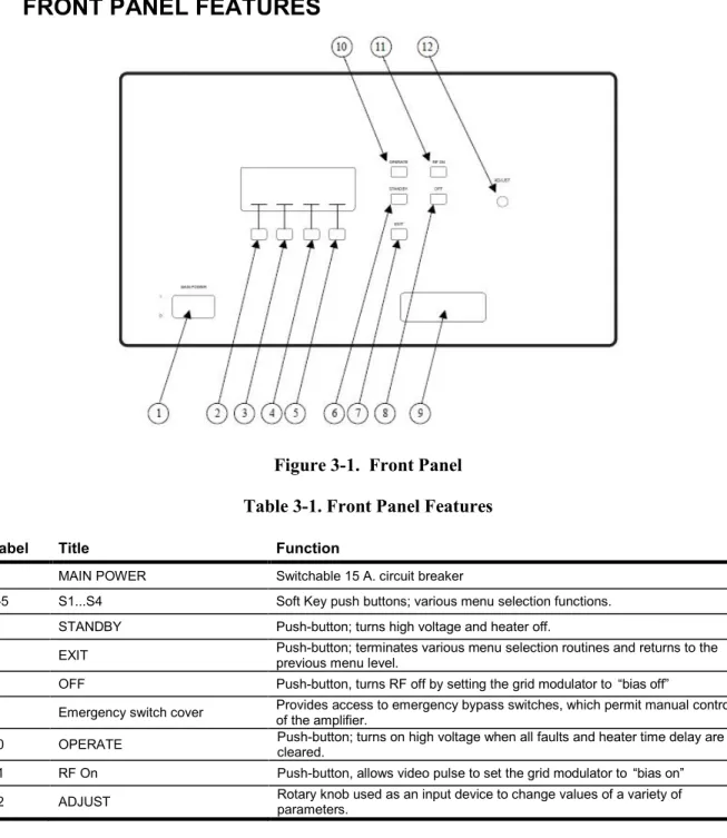
3.3 FRONT PANEL FEATURES
Figure 3-1. Front Panel Table 3-1. Front Panel Features
Label Title Function
1 MAIN POWER Switchable 15 A. circuit breaker
2-5 S1...S4 Soft Key push buttons; various menu selection functions.
6 STANDBY Push-button; turns high voltage and heater off.
7 EXIT Push-button; terminates various menu selection routines and returns to the previous menu level.
8 OFF Push-button, turns RF off by setting the grid modulator to “bias off”
9 Emergency switch cover Provides access to emergency bypass switches, which permit manual control of the amplifier. 10 OPERATE Push-button; turns on high voltage when all faults and heater time delay are cleared. 11 RF On Push-button, allows video pulse to set the grid modulator to “bias on” 12 ADJUST Rotary knob used as an input device to change values of a variety of parameters.
Model 4000TP2G8
10 Rev A
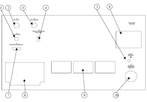
3.3 REAR PANEL FEATURES
Figure 3-2 Rear Panel Table 3-2 Rear Panel Features
Label Title Function
1 PULSE INPUT Modulator Pulse Input: BNC female
2 RF INPUT RF Input: Type N female
3 FWD SAMPLE Forward Power Sample Port: -50dB coupling factor, Type N female
4 RS-422/485 Remote Control Connector: D-Sub 9-pin female
5 SAFETY GROUND Internal and External Safety Ground Stud
6 RF OUTPUT RF Output: WRD-350
7 EXTERNAL INTERLOCK Connector for remote interlock and inhibit functions: D-Sub 15-pin female
8 AIR EXHAUST Convection cooling exhaust
9 AIR INTAKE Convection cooling inlet
10 AC INPUT Circular AC Input connector: 190-260VAC
3.5 FRONT PANEL AND SOFT KEYS
3.5.1
Overview
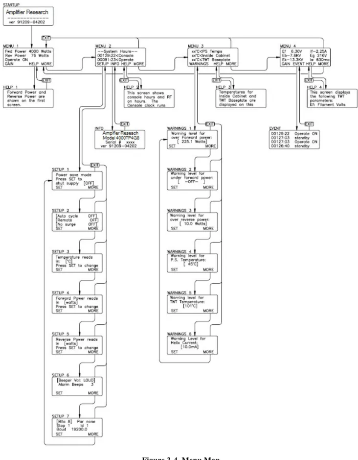
The purpose of the front panel display is to permit the operator to access extensive information about the condition and operation of the TWTA. To accomplish this, a number of informational screens are programmed. It is important for the operator to be able to select the screen with the required information. Screen selection is accomplished by pressing an appropriate soft key, or by pressing the EXIT key. When a soft key is active, its function is displayed on the bottom line of the display. Figure 3-4 provides a “roadmap” for navigating between the screens.
Model 4000TP4G8
Rev A 11
3.5.1.1
Soft Keys
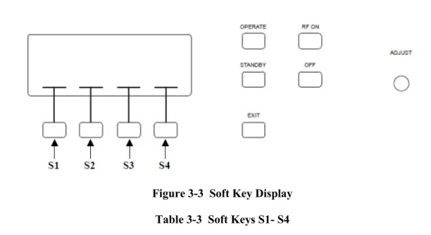
Figure 3-3 Soft Key Display Table 3-3 Soft Keys S1- S4
The current function of each soft key is displayed in the screen area immediately above it.
Key Function
S1 Entry to Setup screens 1-6 from Menu 2; Entry to Warning screens 1-6 from Menu 3 S2 Entry to Faults screen from Menu 4
S3 Entry to contextual help screens from top-level Menus 1 through 4 S4 Entry to next level down; from the lowest level, returns to the top.
3.5.1.2
EXIT
Returns to the top level from within a menu sequence.
3.5.1.3
ADJUST
This knob is used to:
• Set the amplifier gain
• Scroll through lists of menu items
• Select parameter values for change
Model 4000TP2G8
12 Rev A
Model 4000TP4G8
Rev A 13
3.5.2
Menu Screens
Menu Screens - The screens at the highest level are called menu screens. There are four menu screens. At power on, the MENU 1 screen is displayed. Each of the menu screens has the soft key S4 labeled MORE. The MORE key (S4) causes the next menu screen to appear. From MENU 4, MORE causes MENU 1 to reappear. In short, MORE permits scrolling through the menu screens. The EXIT key returns display to MENU 1 from any other menu screen.
The menu screens display system status and parameter levels. They are configured as follows:
Menu 1 Forward power (bar graph, watts, or dB)
Reflected power (bar graph, watts, dB or % forward power)
System status (if a latched fault exists, MENU 1 is displayed with the system shutdown message)
Menu 2 - System Hours -
Console hours (active when main power circuit breaker is on, represents TWT filament hours) Operate hours (active when HV is on)
Menu 3 Power supply temperature (°C or °F) Cabinet temperature (°C or °F) TWT baseplate temperature (°C or °F) Menu 4 Heater voltage (Ef)
Heater current (If) Collector voltage (Eb) Cathode voltage (Ek) Helix current (Iw)
Grid voltage (eg) (If Applicable)
NOTE: Readings and headings on Menu 1-4 will vary depending on the type of HPA. Check test data.
Help Screens S3 - On each of the menu screens 1, 2, 3 and 4 soft key S3 is labeled HELP. If S3 is selected, a message describing the functions of that screen will be displayed. Use the ADJUST knob to scroll through the message. The EXIT key will return you to the screen from which the help screen was called.
3.5.3
Setup Screens
Setup Screens Menu 2 - Labeled SETUP selects the first of the setup screens.
SETUP 1: allows the user to manually shut off the heater power supply and put the HPA into Sleep Mode (see Section 3.5.4). Pressing S1 (SET) toggles between ON and OFF. Pressing MORE again brings up the SETUP 2.
SETUP 2: toggles Auto Cycle On/OFF and Remote. Pressing S1 (SET) changes the selection. The setting displayed when the screen is exited will be retained.
Pressing MORE brings up the next screen, SETUP 3.
Auto Cycle: When primary power is restored after an interruption, the system will return to the On state that existed before the interruption. For example, if the TWTA is at RF On, and Auto Cycle is selected, it will automatically recycle the amplifier to turn RF On after a primary power interruption.
The control system will warn you at power up if Auto cycle is enabled. To cancel, simply press either the RF Off or Standby key.
Remote: When Remote is off, a device connected to the TWTA computer interface may monitor the amplifier's status but may not control the Operate , Standby , RF Off, RF On, or Reset keys. When Remote is On, the external device has full control of the amplifier for safety reasons. Pressing the RF Off or Standby keys cancels the Remote mode, and causes the system to revert to local control.
Model 4000TP2G8
14 Rev A
SETUP 3: toggles display of temperature parameters between Fahrenheit and Celsius degrees. Pressing S1 (SET) changes the selection. The setting displayed when the screen is exited will be retained. Pressing MORE again brings up the next screen, SETUP 4.
SETUP 4: allows a choice of displaying forward power in stripchart form, or in dBm or watts. Pressing MORE again brings up the next screen, SETUP 5.
SETUP 5: allows a choice of displaying reflected power in stripchart form, % of forward power, or in dBm or watts. Pressing MORE again brings up the next screen, SETUP 6.
SETUP 6: toggles the desired number of alarm beeps and the desired beep volume. S1 (SET) toggles between parameters, and the adjust knob is used to enter the data. Pressing MORE again brings up the next screen, SETUP 7.
SETUP 7: allows the RS-422/485 address to be set. Pressing MORE again brings the user back to SETUP 1.
3.5.4
Sleep Mode
Sleep Mode (see Section 3.5.3) - The Sleep Mode feature allows the user to selectively shut off the heater module of the power supply. This can be done manually through the front panel or remotely via the computer interface. This is typically used during extended periods of remote operation to improve tube life, by turning off the filaments (Sleep Mode activated). This eliminates excessive STANDBY hours on the TWTs while still permitting remote capability to turn on the amplifier.
To activate Sleep Mode locally: Press the MORE soft key to get to MENU 2. At MENU 2 press the SETUP soft key to get to SETUP 1. At SETUP 1 press SET to activate Sleep Mode (turn heater and fan off). The system will ask Are you sure? Press SET again.
After activating the Sleep Mode: Screen will display Cooling On while heaters cool down. System Off
notifies user that the amplifier is in Sleep Mode
To de-Activate Sleep Mode locally: Press the ON soft key to de-activate Sleep Mode. Amplifier will return to MENU 1. When de- activating the Sleep Mode the heaters will require at least a 3 minute heater time delay. Wait the full 3 minutes prior to selecting OPERATE.
3.5.5
Warning Screens
Warnings Screens Menu 3 - Labeled WARNINGS, selects the first of six setup screens
WARNINGS 1: allows the operator to enter the maximum forward power. The existing value is between brackets[ ]; pressing SET puts arrows >< around the value, indicating that the adjust knob is active. The effect of the warning setpoint is as follows: if the forward power exceeds the setpoint, the audible alarm will sound (if configured in SETUP 5). This warning will be repeated every thirty seconds until the over forward power condition is cleared. In addition, a warning message will appear on line 3 (the status line) of MENU 1. In the event that the alarm is heard, the operator should go to MENU 1 to determine the cause. Pressing MORE brings up the next screen, Warnings 2.
WARNINGS 2: allows the under forward power set-point to be entered. Adjusting this to the minimum value causes -OFF- to be selected, disabling this alarm. Pressing MORE again brings up the next screen, Warnings 3.
Model 4000TP4G8
Rev A 15
WARNINGS 3: allows for the maximum reflected power level to be set. Note that these are warning levels at which the beep sounds; the actual maximum reflected power level that generates a system fault is set in hardware in the TWT power supply HPA Logic and Control Module. Pressing MORE brings up the next screen, Warnings 4.
WARNINGS 4: allows input of the maximum power supply temperature. Entering this parameter is performed as above. Pressing MORE brings up the next screen, Warnings 5.
WARNINGS 5: allows input of the maximum TWT collector block temperature. If either parameter exceeds the setpoint, the audible alarm will sound every 30 seconds (if configured), and a warning message will appear on line 3 of MENU 1. Pressing MORE brings up the next screen, Warnings 6.
WARNINGS 6: permits setting the maximum helix current. Any helix current above this setpoint will result in an audible alarm (if configured), repeated every 30 seconds; and a warning message is displayed on the status line of MENU 1. Pressing MORE again returns display to WARNINGS 1. As before, pressing EXIT from any of the warnings screens returns display to MENU 3.
3.5.6
Miscellaneous Screens
Info Screen MENU 2 S2 - (labeled INFO) selects a screen that displays the RF sample port calibration factors at various frequencies across the band. In addition, this screen displays the model number, serial number and firmware revision information, which may be required by a service representative when providing technical assistance. The EXIT key returns the display to MENU 2.
Event Screen Menu 4 S2 - Labeled EVENT provides a display of events logged by the control system. These events include AC power-up, heater warm-up, change from standby to operate, faults, and resets. The events are stored in a first-in-first-out (FIFO) software buffer that has room for 100 events; as new events are logged, the older ones are discarded.
System Shutdown Screen - In the event of a system shutdown due to a latched fault (i.e., a fault such as body over-current or power low line that requires a reset), the MENU screen is replaced by a screen indicating the nature of the fault. Soft key S4 (labeled OK) is implemented as a reset key; pressing S4 brings back the MENU screens. Line 3 of MENU 1, which normally displays the operational state of the TWTA, is used as a fault display line until the fault is cleared. When the fault clears the system will automatically resume the standby state and high voltage on will be enabled once again.
Factory Service Screens - A number of screens intended for factory service and calibration are behind passwords and are not accessible to the user.
System Malfunction Screens - A number of screens are reserved to display error messages. These messages are not normally seen and indicate a malfunction of the TWTA. System malfunction messages include the following:
• Database corrupt
• Communication failure
• Cannot restore
• CU line voltage too low to operate. System shutdown
In the event that one of these appears, shut off the TWTA and contact an authorized service representative before proceeding.
Model 4000TP2G8
16 Rev A
CAUTION:
Attempts to operate the TWTA despite control unit problems may result in loss of the static RAM database and calibration
information.
3.6 INITIAL TURN ON AND WARM-UP PROCEDURE
Before Applying Power
1. Verify that the equipment line voltage is compatible with the TWTA.
NOTE: If the user does not have a 5VDC max TTL signal pulse connected to the pulse input BNC connector, there will be no RF output.
2. Install the TWTA as discussed in Section 3.2. Provide an RF generator to the RF input Type N connector. Set RF generator level below -50dBm and set desired frequency in specified range. Connect a load suitable for 8000 watts peak operation to the output connector. The load VSWR should be less than 2.0:1. A power meter and suitable attenuators may be connected to the RF sample port. (Refer to RF sample port calibration factors on the rear of the unit or on the Info screen in MENU 2). These show the relationship between the amplifier output power and the RF sample port power as a function of frequency. When only the power of the fundamental frequency is to be measured and when operating near rated power use filters, a frequency selective receiver, or a spectrum analyzer to reduce the harmonic content of the measured level.
3. Switch on the MAIN POWER circuit breaker. The fan will operate. Allow three minutes for the filaments on the TWTs to warm up.
The front panel display will show several identification messages and then MENU 1 screen. The third line will indicate the heater time delay is active. Allow the heater warm-up delay to expire. Line three will indicate STANDBY/READY.
4. Push S4 (MORE) three times to go to MENU 4. Verify that the heater voltage and current are near their nominal levels. The values of these parameters at the time the TWTA left the factory are logged on the test data sheet.
5. Push the OPERATE push-button. Stay in Menu Screen 4. You will now see the cathode and collector voltages rise. Verify that the collector and cathode voltages are near nominal. The values of these parameters at the time the TWTA left the factory are logged on the test data sheet.
6. Set Gain to 0%. Push RF ON, check the helix current (Iw). The helix current should be close to the nominal value for no RF drive. The value of this parameter at the time the TWTA left the factory is logged on the test data sheet.
7. Push S4 (MORE) or EXIT to get to Menu 1 . 8. Set the TWTA gain to maximum.
9. Adjust the RF generator to slowly increase the RF drive toward 0 dBm to reach the desired forward power on the display and power meter (connected to the forward sample port). The forward power display will become active, with a maximum reading when peak power output is achieved.
Model 4000TP4G8
Rev A 17
An alternate procedure is to pre-set the gain to a minimum, set the RF generator to 0 dBm and then slowly increase the TWTA gain to set the desired RF output level.
Observe that the helix current is sensitive to the RF drive level of the TWT. It is at a minimum with no RF drive. The helix currents with no drive and with rated RF output mid-band are logged on the test data sheet. The value of the helix current is a good qualitative indicator of RF drive present.
To shut the system down, push RF OFF and then STANDBY. Allow the TWTA to cool down until the TWT temperature drops below 50°C, then turn off main power.
3.8 RF OPERATION
NOTE: If the user does not have a 5VDC max TTL signal pulse connected to the pulse input BNC connector, there will be no RF output.
The RF chassis is provided with a front-panel BNC connector which must be connected at all times to generate RF output. The impedance of the pulse gate input is approximately 50 ohms.
For Pulsed operation, provide a TTL pulse signal from a pulse generator at the BNC connector on the rear panel of the RF chassis. In pulse mode the signal will be used for pulsing the beam of the TWT and hence the RF output. As compared with providing a pulsed RF input, pulsing the beam of the TWT offers low noise between pulses. It also offers reduced prime power consumption for low duty factor pulsing, since the beam current is off most of the time.
Best performance is obtained when the input RF drive is set at or just below the level which causes peak power output. Do not set input drive above 0 dBm
CAUTION:
Input drive above +10 dBm may damage the unit
The reverse (reflected) power level should remain below 10% of the forward power, assuming that the output is properly matched.
Model 4000TP2G8
Rev A 19
4. MAINTENANCE
The TWTA does not require routine scheduled maintenance. The only moving parts are the elements of switches, relays and the fans. Preventive maintenance is recommended in Section 4.3.
The TWTA is basically a factory repairable unit. However, since limited logic schematics and partial parts information is supplied in this manual (Section 5) some user service organizations may choose to perform their own corrective maintenance. Warnings and Cautions should be observed.
4.1 SAFETY WARNINGS AND CAUTIONS
WARNING:
Adjustment, maintenance, and repair of the equipment must be
performed only by qualified personnel. Service work must be performed only by technicians thoroughly familiar with the high voltages present in microwave tube amplifiers in general, and with this equipment in
particular.
Never handle the TWT leads or the high-voltage connectors unless the unit is unplugged and it has been positively established that the high-voltage filter capacitors have been discharged to a known safe level.
CAUTION:
A malfunctioning power supply can cause damage to the TWT. If you are troubleshooting the TWTA, remove the TWT and substitute suitable loads to prevent damage to the TWT.
Replacement fuses are required to be of specific type and current rating.
4.2 UNAUTHORIZED REPAIRS
CAUTION:
Unauthorized repairs or modification of this product during the warranty period may void the warranty. In the event that the TWTA malfunctions while it is still under warranty, always contact an authorized service representative.
4.3 PREVENTIVE MAINTENANCE
The RF characteristics and power supply voltages and currents of the TWTA should be logged on a regular basis. Maintenance should be performed if significant deviations from the logged values appear. If the unit is under warranty, contact an authorized service representative if impaired performance is suspected.
The frequency of service depends on the environment where the TWTA is used, and must be determined by inspection. If significant dust has been noted on or around the air intake grill, it may be desirable to vacuum the dust and debris from inside the chassis. To open the chassis:
Model 4000TP2G8
20 Rev A
1. Remove the amplifier from the cabinet or rack as follows:
NOTE: Due to the weight of the unit, the removal of the amplifier from the cabinet or rack is a two-person operation.
2. Disconnect power and any other cables or waveguide. Remove any screws connecting the HPA to a rack or cabinet. Carefully remove the HPA from the rack or cabinet. If slide rails are used, depress the buttons on each slide rail to remove the unit from the rack.
3. Remove the screws that secure the upper and lower covers. Remove the covers to gain access to the interior of the TWTA.
4. Vacuum dust and debris from inside the chassis. Clean dust from the TWTA and its flying leads. Remove any dirt from around the three high voltage connectors. While the cover is off, check for loose wires, components or fasteners.
5. Re-assemble in the reverse order.
Maintenance Actions (Review)
Periodic maintenance of AR amplifiers consists of 3 primary actions:
• Clean around the air intake grill on a regular basis.
• Maintain a log of the amplifier’s operating parameters. This will allow identification of problem areas before faults occur and allow quick corrective action.
• Keep the equipment as clean as possible and ensure that the front panel buttons are kept clean from dirt and dust ingress.
4.4 TROUBLESHOOTING
Symptom Possible cause
TWT or power supply overtemperature Air inlet grille blocked or dirty Collector heat sink dirty
Inadequate clearance behind TWTA High air inlet temperature
Defective blower or power supply
No response when main power turned on External breaker tripped
Fan comes on but control module display does not come up; unit
does not beep when powered up Defective control module or control module power supply
Control module does not boot EPROM(s) missing.
Control module datalink failure error appears HPA interface failure. Fiberoptic link failure +15 VDC supply failure
Heater power supply does not come up Defective low voltage power supply module Defective heater power supply module
No high voltage Open external interlock
Keylock switch on INHIBIT or REMOTE
Defective high voltage power supply. Voltages normal, but no RF output, helix current low No RF input
Defective remote control board Defective SSA
Model 4000TP4G8
Rev A 21
After review of the symptoms of the failure, the user may want to check for a loose connector or component especially after rough handling of the unit. Look externally for physical damage and internally for unmated or loose parts.
The service technician should become familiar with the internal mechanical construction to permit correct re-assembly. Limited troubleshooting may be conducted, with caution, based on the failure symptom and an understanding of the logic/schematic diagrams.
4.5 NON-REPAIRABLE MODULES
The following modules are encapsulated and not repairable. Contact an authorized service representative if replacement modules are needed.
A27824-100 Heater Power Supply Module A30594-001 Grid Modulator Assembly A33176-001 High Voltage Filter Assembly A33185-000 High Voltage Diode/Cap Assembly A33090-001 Capacitor Bank
4.6 RECOMMENDED SPARE PARTS
A27824-100 Heater Power Supply Module A30467-000 Power Inverter
A30594-001 Grid Modulator Assembly A33176-001 High Voltage Filter Assembly A33185-000 High Voltage Diode/Cap Assembly A23683-003 Power Factor Correction Module A26452-150 Low Voltage Power Supply Module E02822-000 SSPA, C-Band, 4.0-8.0 GHz E01120-000 Fan 11000 RPM, 400Hz
Model 4000TP2G8
Rev A 23
5. TECHNICAL DOCUMENTATION
The purpose of this technical documentation section is to provide a guide to the TWTA for technician-level servicing. It is intended for use by qualified technical personnel who must troubleshoot and repair the TWTA in the field. Such repairs are typically limited to replacement of modules or major components. For this reason, documentation pertaining to the highest levels of the system and to system control logic are included.
Model 4000TP2G8
Model 4000TP4G8
Rev A 25
5.1 TOP LEVEL BUILD TREE (SEE APPENDIX C)
5.1.1
A38004-100
Pulsed HPA
Level Item Number Item Description Qty Ref Des
1 10-38004-100 HPA, 4KW PULSED, 43PC 0
1 14-38004-100 ATP, 43PC 0
1 15-38004-100 PRODUCT SPEC, 43PC 0
1 33-38004-100 LABEL, 43PC 0
1 80-38004-100 43PC PACKAGE OUTLINE 0
1 85-27500-001 BLUE BOOK, PULSED UNIT 0
1 91-91209-04202 43PC,PS,422 0
1 A23692-000 INSULATED FAN DRIVER 1 A1
1 A25444-001 HPA INTERFACE BOARD (200UM GLASS FIBERS) 1 A2
1 A27392-007 RF OUTPUT PROTECTION BOARD, ARC DETECT, NO LASER,
+5VDC IN 1 A3
1 A27506-102 HPA SYSTEM CONTROL FRONT PANEL, SINGLE PHASE 1 A4
1 A27509-001 CONTROL UNIT ASSY, RS-485, 200UM HCS 1 A5
1 A30445-006 WIRING KIT, 43PC 1 A13
1 A30447-008 MICROWAVE POWER ASSY, 43PC 1 A7
2 A31674-000 HARNESS,FIBER OPTIC,ARC DETECTOR 2 A1,A6
2 E00888-015 CABLE,RF FLEX,15,SMA,M TO M,20 GHZ,50 OHM,0.141 CABLE,
[SRC 150-150-150150] 2 W6,W7
2 E01376-000 COUPLER, -10DB, 0.8 - 4.2 GHZ SMA, 2 KWPIC, 50W, AVG.,
FEMALES, [RLC M-3728] 1 A5
2 E02595-002 TWT, 4.5KW, 4.0 - 8.0 GHZ, PULSED 4% DUTY, +/- 4DB EQ,
WRD-350, [TELEDYNE, MEC-3103] 1 A4
2 E02672-000 RF GASKET, WRD-350 GROOVED FLANGE, D-STYLE
[CONTINENTAL MICROWAVE, GSK350] 1
2 E02814-000 OUTPUT ARM, 4-8 GHZ, DUAL COUPLERS, ARC DETECTOR,
WRD-350 [APOLLO, TBD] 1 A2
2 E02822-000 SSPA, 4-8 GHZ, 35DBM OUT, 37DB GAIN [KMIC TBD] 1 A3
2 E20145-000 FILTER,LOW PASS,8 GHZ, SMA(MICROLAB/FXR LA-80F) 3 FL1,FL2,FL3
2 E20284-000 ZERO-BIAS SCHOTTKY DETECTOR,10MHZ-18.5GHZ,POSITIVE
OUT PUT POLARITY,(RLC, M-3747) 2 D1,D2
1
A30537-102 HV BREAKOUT BOX, NO POTTING, EG REF TO EK, SAME AS -100 WITH SHORTER LEADS AND ALTERNATE PACKAGING 1
A14 1
A30750-006 PULSE MONITOR BOARD, SAME AS -001 WITH VSWR TRIP LEVEL ADJUST TO 1.2V AND CROWBAR JUMPER INSTALLED 1
A8
1 A30770-004 POTTED RESISTOR ASSEMBLY 1 A9
1 A30771-002 RESISTOR CAPACITOR SNUBBER ASSY 1 A10
1
A30956-001 OPTICAL RS-485/RS-422 BOARD (200UM HCS OPTICS) 1 A11
1
A33053-100 POWER CORD ASSEMBLY, SINGLE PHASE, 240VAC, 20A 1
1
A33069-100 POWER SUPPLY, TWT MEC-3103, SINGLE TWT WITH PFC 1 A6
2
Model 4000TP2G8
26 Rev A
Level Item Number Item Description Qty Ref Des
2
A23065-001 INPUT FILTER MODULE, PHASE LOST DETECTION NOT USED 1 A7
2
A23683-003 AVR CURRENT MODE PFC, 3KW , 200-250VAC INPUT ( CAN OPERATE WITH A23065-001 ) 1 A9
2 A26452-150 LOW VOLTAGE POWER SUPPLY MODULE 150W 1 A8
2 A27816-000 MOTHER BOARD 1 A10
2 A27818-000 TANK MODULE (NO CAPS) 1 A4
2
A27824-100 HEATER SUPPLY, HI POWER, 6.3V 6A, WITHOUT CATH REF INPUT LEAD 1 A1
2 A30467-000 PHASE & POST POWER INVERTER 1 A6
2
A30594-001 GRID MODULATOR MODULE, W/O CATH REF INPUT LEAD 1 A2
2
A33176-001 HV FILTER FOR TWT MEC 3102 AND MEC 3103 WITHOUT EXTERNAL CAP ASSY 1 A3 2
A33185-000 HV RECTIFIER & TRANSFORMER ASSEMBLY FOR 83PC 1 A5
1 A33090-001 CAPACITOR BANK FOR ONE TWT, 43PX 1 A12
Model 4000TP4G8
Rev A 27
5.2 SCHEMATICS
10-23050-085 HPA Logic and Control (A23050-085) 10-25444-001 HPA Interface (A25444-001) 10-25450-000 CPU Board (A25450-000) 10-38004-100 43PC Pulsed HPA
Model 4000TP2G8
Model 4000TP4G8
Rev A 29
5.3 PARTS LISTS
A23050-085 HPA Logic and Control Assembly A25444-001 HPA Interface Board
Model 4000TP2G8
30 Rev A
5.3.1
HPA Logic and Control Board (A23050-085)
Item Number Item Description Qty Ref Des
10-23050-085 HPA LOGIC AND CONTROL 0
61-23050-083 NOTES 0
B23050-000 LOGIC & CONTROL BOARD 1
C06103-000 CAP, 10MF, +/-20%, 25V, SOLID TANT, RADIAL [KEMET
T356E106K025AS] 2 C48,C49 C16333-000 CAP,33MF,25V,AERL,(NICHICON UVX1E330M) 1 C11 C17104-000 CAP,100UF,63V,AERL,(NICHICON, UVR1J101MPD) 1 C47 C31028-000 CAP,1000PF,200VDC,10%,CER,1% FAILURE,(KEMET CKR05 SERIES W/"V" OPTION) 3 C2,C5,C15 C31032-000 CAP,0.01MF,200VDC,10%,CER,1% FAILURE,(KEMET CKR06 SERIES W/"V" OPTION) 17 C9,C13,C14,C17,C19,C21,C22,C27,C28,C30,C31,C33,C34,C36,C41,C46,C58 C31036-000 CAP,0.1MF,100VDC,10%,CER, (KEMET, M39014/2-1310V) 5 C10,C24,C52,C101,R69 C31039-000 CAP,0.47MF,50VDC,10%,CER,1% FAILURE,(KEMET CKR06 SERIES W/"V" OPTION) 1 C99
C31040-000 CAP,1MF,50VDC,10%,CER,1% FAILURE,(KEMET CKR06 SERIES
W/"V" OPTION) 18 C1,C3,C4,C6,C7,C16,C18,C25,C26,C32,C37,C38,C39,C40,C43,C44,C45,C50 C31065-000 CAP,2.7MF,50V,10%,CER,1% FAILURE,(KEMET CSR13G275KM) 1 C100 D10965-000 ZENER,15V,(FAIRCHILD SEMICONDUCTOR, 1N965B) 3 D16,D23,D31 D14454-000 DIODE,AXIAL,(FAIRCHILD SEMICONDUCTOR, 1N4454) 22 D1,D3,D5,D7,D8,D9,D10,D11,D12,D13, D17,D18,D19,D21,D25,D26,D28,D29,D 30,D35,D37,D38 D14728-000 ZENER,3.3V,1W,10%,AXIAL,(MOTOROLA 1N4728) 1 D24 D14733-000 ZENER,5.1V,1W,10%,AXIAL,(FAIRCHILD SEMICONDUCTOR, 1N4733A) 1 D36
F00101-000 WASHER,#4 NAS,(PRO-STAINLESS NAS620C4) 4
F00107-000 #4 SPLIT LOCK WASHER,SST 2
F31004-000 NUT,4-40,HX,SMALL PATTERN,MIL-SPEC 2
G00043-000 HEX STANDOFF ,4-40 THREAD SS,FOR D SUBMIN CONN (PRO
STAINLESS, 620013) 2
J10370-000 CONN,37 PIN,MALE,D-SUB,PCB RIGHT ANGLE, (AMP, 747252-4) 1 J2 J12294-000 CONN RIGHT ANGLE MALE 29 PIN,(SAME AS J12291 W/NO
MODIF),(HYPERTRONIC KA29/127BPMC10T,&HARDWARE 1 J7 J18086-000 CONN,,SMA,JACK RECEPTACLE,RIGHT ANGLE,0-18GHZ,PC
MOUNT [JOHNSON COMPONENTS 142-0701-301] 2 J4,J5
L00200-000 WIDE BAND CHOKE,(VK200 10/3B FERROXCUBE) 1 L1
N23061-000 MODULE CHASSIS LOGIC 1
Q22907-000 TRANSISTOR,PNP, (ST, 2N2907A ) TO-18 1 Q2
Q26661-000 FET, 90V @ 1.5A ,N.CH DMOS, (T.O.39) POWER (SSD)
(SUPERTEX, 2N6661) 1 Q1
R00100-000 RES,10 OHM,1/4W,5%,CC,(OHMITE, OD100JE) 6 R1,R9,R19,R37,R44,R50
R01100-000 RES,100 OHM,1/4W,5%,CC,(OHMITE, OD101JE) 5 R4,R20,R27,R29,R39
R02100-000 RES,1K,1/4W,5%,CC,(OHMITE, OD102JE) 11 R5,R7,R17,R18,R28,R34,R45,R59,R71 ,R72,R87 R02330-000 RES,3.3K,1/4W,5%,CC,(A/B RC07GF332J) 1 R43 R02470-000 RES,4.7K,1/4W,5%,CC,(OHMITE, OD472JE) 3 R30,R31,R36 R02560-000 RES,5.6K,1/4W,5%,CC,(OHMITE, OD562JE) 1 R75 R03100-000 RES,10K,1/4W,5%,CC,(OHMITE, OD103JE) 1 R38 R05820-000 RES,8.2M,1/4W,5%,CC,(OHMITE, OD825JE) 1 R35
R20243-000 RES,243 OHM, 1%,MF,100PPM,(DALE RN55D2430F) 1 R23
R21100-000 RES,1K, 1%,MF,100PPM,(DALE RN55D1001F) 1 R49 R21301-000 RES,3.01K, 1%,MF,100PPM,(DALE RN55D) 1 R10 R21402-000 RES,4.02K, 1%,MF,100PPM,(DALE RN55D) 1 R67 R21750-000 RES,7.5K, 1%,MF,100PPM,(DALE RN55D) 1 R24 R21887-000 RES,8.87K, 1%,MF,100PPM,(DALE RN55D) 2 R52,R73 R22105-000 RES,10.5K, 1%,MF,100PPM,(DALE RN55D1052F) 1 R98 R23100-000 RES,100K, 1%,MF,100PPM,(DALE RN55D1003F) 9 R6,R42,R47,R48,R60,R61,R74,R99,R1 00 R23169-000 RES,169K,1%,MF,100PPM,(DALE, RN55D) 1 R54 R23249-000 RES,249K, 1%,MF,100PPM,(DALE RN55D) 2 R46,R53 R23698-000 RES,698K, 1%,MF,100PPM,(DALE RN55D6983FB14) 3 R33,R40,R55 R23750-000 RES,750K, 1%,MF,100PPM,(DALE RN55D) 1 R41 R23953-000 RES,953K, 1%,MF,100PPM,(DALE RN55D9533F) 1 R66
Model 4000TP4G8
Rev A 31
Item Number Item Description Qty Ref Des
R30035-000 RES,10K, 1%,MF,100PPM,(DALE RN55D1002F) 2 R21,R62 R31091-000 RES,47K,1/4W,5%,CC,<=1% FAIL,(A/B RCR07) 1 R32 R32004-000 TRIMPOT,1K,1/2W,10%,CERMET,20T,SIDE ADJ,(BI TECHNOLOGIES, 67XR1KLF) 1 R11 R32020-000 TRIMPOT,10K,1/2W,10%,CERMET,20T,SIDE ADJ,(BI TECHNOLOGIES, 67XR10KLF) 3 R12,R15,R16 R32049-000 TRIMPOT,5K,1/2W,10%,CERMET,20T,SIDE ADJ,(BI TECHNOLOGIES, 67XR5KLF) 2 R13,R14
U02390-000 IC,QUAD COMPARATOR,(NAT LM139J) 3 U4,U5,U6
U03240-000 IC,LOW POWER OP AMP,(NAT LM324) 1 U7
U10070-000 REFERENCE,PRECISION 10V [LINEAR TECH LT1031DCH] 1 U9
U17805-000 IC,5V REGULATOR,TO-220,(NAT LM340T-5.0) 1 U8
U20148-000 IC,HEX INVERTER,SCHMIDTT TRIGGER,(74HC14) (SSD) 3 U1,U2,U3
U30106-000 IC,10K,RES NETWORK,6 PIN,SIP (DALE MSP06A-01-103G) 2 RP4,RP8 U30410-000 IC,10K,2%,0.40A,10 PIN,ISOLATED RESISTORS (DALE
MSP10C-03-103G OR BOURNS 4610H-102-103) 6 RP1-2,RP5-7,RP9