(will be inserted by the editor)
A CAD Interface for GEANT4
C M Poole, I Cornelius, J V Trapp, C M LangtonAbstract Often CAD models already exist for parts of a geometry being simu-lated using GEANT4. Direct import of these CAD models into GEANT4 however, may not be possible and complex components may be difficult to define via other means. Solutions that allow for users to work around the limited support in the GEANT4 toolkit for loading predefined CAD geometries have been presented by others, however these solutions require intermediate file format conversion using commercial software. Here within we describe a technique that allows for CAD models to be directly loaded as geometry without the need for commercial soft-ware and intermediate file format conversion. Robustness of the interface was tested using a set of CAD models of various complexity; for the models used in testing, no import errors were reported and all geometry was found to be navigable by GEANT4.
Keywords Monte Carlo, GEANT4, computer aided design, CAD, geometry
1 Introduction
Geometry & Tracking 4 (GEANT4) is a C++ toolkit specifically designed to track particles traversing a geometry whilst being subject to physical processes [7, 8], it finds application in fields such as nuclear and particle physics, space engineering, and medical physics [10, 14, 15, 18]. Numerous physical processes can be mod-eled including photo-nuclear interactions, optical processes such as scintillation and Cherenkov radiation and other particle interactions over a wide energy range (250eV up toT eV energies); the full gamut of processes available to the user is described by others [7, 8]. Fast and effective geometry definition is available to the user with constructs such as G4Orb for defining orbs, G4Box for defining rect-angular prisms and the concept of boolean solids. Complex and irregular solids defined by a surface mesh can also be created using theG4TessellatedSolid [7, 8]. C. M. Poole is with Cancer Care Services, Royal Brisbane and Womens Hospital, Herston, QLD 4029, Australia.·C. M. Poole, I. Cornelius, J. V. Trapp and C. M. Langton are with the School of Chemistry, Physics and Mechanical Engineering, Science & Engineering Faculty, and the Institute of Health and Biomedical Innovation, Queensland University of Technology, Brisbane, QLD 4000, Australia. E-mail: [email protected]
(a) (b) (c)
Fig. 1 A diagrammatic comparison between two currently available CAD import techniques where (a) shows the technique described in persistence example G02, (b) shows the STEP to GDML conversion technique [12], and (c) shows the new direct import technique proposed here within.
Currently however, there is limited support for directly loading pre-existing or user defined computer aided design (CAD) models as geometry in GEANT4, whether it be an arrangement of primitive solids, or a surface mesh. Of the two methods available, both are reliant on intermediate file format conversion using commercial software [9, 12] and can only load CAD models described using the standard for the exchange of product model data (STEP - ISO 10303) [16].
ISO standard STEP is a CAD format designed to supersede the still widely used initial graphics exchange specification (IGES) [2,16]. As such STEP has previously been the target format for loading CAD geometry into GEANT4. The persistence example with identifier ‘G02’ distributed with GEANT4 describes loading STEP Tools (STEP Tools Incorporated, New York) files directly. Intermediate conversion of STEP to STEP Tools is required using the commercial ST-Viewer program or ST-Developer libraries (STEP Tools Incorporated, New York). This process, shown in Fig.1(a) allows for assemblies of components to be loaded directly, however the STEP Tools programs and libraries may be prohibitively expensive for some users. Constantine et al [12] described the process of converting STEP to geometry description mark-up language (GDML) using the commercial software FastRad (Tests & Radiation - Toulouse) [9], refer to Fig.1(b). Functionality within the GEANT4 toolkit already allows for geometries to be saved and reloaded using GDML [11], it is based on extensible mark-up Language (XML), allowing for persistence of many aspects of the GEANT4 geometry hierarchy [11]. However, as with the method used in GEANT4 persistence example ‘G02’, FastRad may also be considered prohibitively expensive for some users as it has a requirement of annual licensing, in addition to this the trial version limits the conversion process to no more than 20 elements per assembly.
Loading CAD models as geometry in a GEANT4 Monte Carlo simulation is particularly useful in instances where the geometry is such that it would be difficult to define with an arrangement of primitive solids. Typical examples include the description of components in beamlines such as targets, filters and collimators and for medical applications, metallic implants such as hip prostheses and anatomical structures derived from x-ray CT scans. CAD based geometry allows for more accurate simulation based representations of an experimental setup to be attained more rapidly [12], especially if parts of the experimental setup have already been
designed using CAD software. Whilst using a CAD model as geometry in GEANT4 may reduce the possibility of error when compared to manually creating a geometry in GEANT4 [12], any requirement to convert the CAD geometry to an intermediate file format gives rise to the potential for incorrect geometry definition, especially in instances where the source CAD geometry is undergoing regular modification and intermediate file conversion is not automated or in sync with revisions to the source CAD file.
Programming toolkits already exist for the creation and manipulation of trian-gular and quadrantrian-gular boundary representation (BREP) meshes; the same kinds exportable by many modern CAD packages [5, 13, 17]. Most notably the freely available templated C++ library VCGLIB (Visual Computing Laboratory, Italy) offers advanced mesh manipulation functionality and point cloud surface recon-struction algorithms. In addition to this, VCGLIB already offers an import/export interface for many common CAD file formats [5]. Herein we describe a very simple technique that allows for BREP CAD models to be directly loaded as tessellated solids in GEANT4. The technique is capable of handling many BREP file for-mats exportable by CAD programs whilst not relying on intermediate file format conversions.
2 Methods
The GEANT4 (version GEANT4.9.5 patch 1) geometry hierarchy is divided into solids, logical volumes and physical volumes where solids describe shape, logi-cal volumes define material properties and mother-daughter relations, and phys-ical volumes define placement within the mother volume [7, 8]. The equivalent GEANT4 solid to a BREP geometry is the tessellated solid (G4TessellatedSolid) and has specific properties so as to enable correct geometry navigation by the GEANT4 kernel. In particular, the tessellated solid must describe a closed sur-face, that is to say the boundary between the inside and outside of the solid is defined for all points. Furthermore, all faces on this surface (whether they be tri-angular or quadrtri-angular faces), must not have coincident vertexes; for example a triangular face must have exactly three unique vertexes thereby ensuring it has an area greater than zero. When a face is added to the solid, the direction and order of the vertexes must be anti-clockwise when the normal of the face is pointing to-wards the inside of the volume; the GEANT4 navigator uses this convention when it determines if a point is inside or outside of the tessellated solid. For tessellated solids with face vertex order in the opposite direction, navigation errors may arise. Additionally, boolean operations can not be performed with tessellated solids.
As common BREP CAD file formats and GEANT4 tessellated solids encode a surface mesh in similar ways, a direct mapping can be achieved by iterating over all of the faces in a BREP and adding them directly to the tessellated solid in GEANT4. For a direct mapping to be effective however, vertexes and faces defined in a BREP must be accessible in a common way that is independent of the source file format. This common access to various CAD file formats is achieved here using VCGLIB. Various custom types derived from VCGLIB base classes may be defined so as to describe for example a stereo-lithography format (STL) [1] or Stanford polygon file format (PLY) [6] mesh and the elements that encode it, such as vertexes, edges and faces. Template parameters are used to
attach attributes such as position for example to these custom types, in effect each custom type becomes a collection of specific VCGLIB attributes; a comprehensive description of this scheme is provided in the VCGLIB documentation [5]. Wrappers as they are referred to in VCGLIB extend the core to provide mesh manipulation functionality including importers, exporters and mesh refinement tools, generally the arguments that these wrappers expect are instances of custom types inheriting from VCGLIB base types. Here a custom VCGLIB type is defined that acts as the access layer between common CAD files and GEANT4, the process is automatic and transparent to the user. Implementation, usage and validation of this scheme is detailed in the following.
2.1 Design of the Interface 2.1.1 Implementation
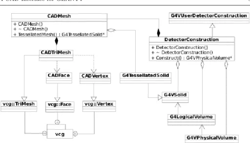
Referring to the unified modeling language (UML) diagram [4] in Fig.2, the core of the proposed CAD interface is a mapping between the VCGLIB derived CAD-TriMesh class which is comprised of faces and vertexes, and the GEANT4 G4 TessellatedSolid class. This mapping is performed automatically with an instance of the CAD interfaceCADMesh class, and unlike the manual solutions described above, requires no intermediate files or manual manipulations using commercial software. Upon creating an instance of CADMesh and supplying it with the file name and type of the target CAD file, an instance ofCADTriMesh is populated with a mesh described in the CAD file. A VCGLIB import wrapper is used to perform this action, with avcg::tri::io:: ImporterPLY wrapper used to populate CADTriMesh with a mesh described in a PLY formatted file for example. At this point, CADTrimesh enables access to the contents of the CAD file in a manner that is independent of its format. Other triangular facet mesh importers provided by VCGLIB include: Wavefront geometry definition (OBJ), Geomview object file format(OFF), STL files and more [5].
Given thatCADTriMesh is now populated with vertexes and faces describing a mesh, the CADTriMesh::FaceIterator iterator is used to iteratively instantiate a GEANT4G4TriangularFacet for each face. Subsequently, these faces are added to the tessellated solid using the G4TessellateSolid::AddFacet method. Once the iterator has looped over all faces, theG4TessellatedSolid::SetSolidClosedmethod is called, preventing further faces from being added to the volume. TheCADTriMesh object is set public so the user may interact with it and VCGLIB directly from within GEANT4, however this is not required if the user simply wants to load a supported CAD file into GEANT4.
2.1.2 Usage
At the user level, all functionality provided by the CAD interface is contained within an instance of the CADMesh object, which can be made available to the user with the inclusion of theCADMesh.hh C++ header file in the user detector construction. Instantiation of a CADMesh object and a call to the CADMesh:: TessellatedMesh method generates and returns a G4TessellatedSolid suitable for inclusion in the user geometry in the same manner as with any typicalG4VSolid
Fig. 2 UML class diagram showing interaction between VCGLIB, CADMesh and a GEANT4 user detector construction. The symbols have the usual meaning when considering a UML class diagram [4]. C++ class names prefixed byG4,CADandvcgbelong to GEANT4, the described CAD interface, and VCGLIB respectively andDetectorConstructionis a user defined class.
object. Following the standard GEANT4 geometry hierarchy, material properties and volume meta-data unique to the volume can be assigned with association to a G4LogicalVolume, and placement of theG4TessellatedSolid within a mother volume with association to a G4PhysicalVolume. Constructor arguments include the file name for the file that contains the mesh, a file type identifier, and op-tional arguments specifying the units of the coordinates described in the file, a G4ThreeVector used to offset the mesh in thex,yandzdirections, and a boolean option - reverse. The reverse boolean option results in faces being added to the TessellatedSolid with the order of their vertexes opposite to what is reported in the source CAD file should the vertex order be opposite to what is required for aG4TessellatedSolid. CAD file types currently supported by the interface include OFF, PLY, STL and COLLAborative Design Activity digital asset schema (COL-LADA) [3].
The source code of the interface is distributed with an autoconf script for testing for, and locating the required dependencies of the CAD interface, as well as generating a Makefile for compilation of theCADMesh.soshared object library. A working installation of GEANT4 is required for successful compilation of the library, additionally the source code for VCGLIB – which is freely available on the internet [5] – is required to enable support for loading OFF, STL and PLY files. From the users perspective however, direct interaction with VCGLIB is not required as it is used internally and automatically by the CAD interface. Once compiled, user code requires linking against CADMesh.so in the usual way, a process which is documented as a part of the source code distribution of the library.
2.2 Validation of the Interface
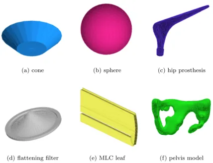
Six test volumes were used to verify the performance of the GEANT4 CAD in-terface. Three simple geometries, a truncated cone and a sphere generated using MeshLab (Visual Computing Laboratory, Italy) and an artificial hip (generated in-house) were saved in all formats capable of import by the CAD interface. Ad-ditionally, a flattening filter from a Varian clinical linear accelerator, a single leaf from a Varian multi-leaf collimator and a model of a pelvis from a CIRS Pelvic Phantom (Model 048) were loaded into GEANT4 using the CAD interface. Each volume, when loaded was visually inspected for qualitative geometric integrity us-ing the GEANT4 OpenGL viewer. Tessellated solid meta-data was dumped for each solid using theG4TessellatedSolid::DumpInfomethod providing a list of each face and vertex coordinate used to define the GEANT4 volume. This data was then compared directly to the original CAD file describing the same volume. A pass level of 100% matching was set, no rounding errors of the vertex coordinates were accepted and vertex and face counts had to agree exactly.
So as to ensure the loaded geometries were navigable by the GEANT4 kernel, each volume was assigned the materialG4 WATER and positioned at the center of aG4 AIR filled world volume. A general particle source (GPS) was initialized and configured to produce a beam of geantinos (the standard GEANT4 debugging pseudo-particle) aimed at the test volume. Each test volume was bombarded with 100,000 geantinos with the tracking verbosity level set to one and the step length set to 0.1mm, ensuring any navigation errors associated with the imported CAD geometry were output; the angular distribution of the beam was set so as to target the entire volume ensuring all faces were inside the beam. At any time, if the navigator was unable to determine if it was inside or outside of the tessellated volume as a consequence of invalid volume definition, the test was failed. Geometry overlap tests build into GEANT4, accessible via the/geometry/test/ user interface commands were also used to verify the correct definition of all geometries loaded using the CAD interface.
3 Results
Fig.3(a), Fig.3(b) and Fig.3(c) show three simple geometries loaded into GEANT4 via the CAD interface described in section 2.1. Further to this, Fig.3(d), Fig.3(e) and Fig.3(f) show more complex geometries loaded into GEANT4. All test volumes imported using the CAD interface, independent of the CAD file format, passed qualitative visual inspection - no corruption of the geometry was visible. Table 1 displays the vertex and face counts for each volume; there was no difference between the vertex and facet counts reported by VCGLIB or GEANT4.
A comparison between the original CAD file and the dumped face and vertex information from each tessellated solid generated no errors. Additionally, the in-built geometry overlap tests, when performed on all test geometries loaded using the proposed CAD interface, found that the geometry was valid. When bombarded with a simulated source of geantinos, no navigation errors were reported. In the case that a face were to be purposefully excluded from the G4TessellatedSolid, the volume would be unnavigable as a consequence of an undefined ‘inside’ or ‘outside’, known as a non-closed solid.
(a) cone (b) sphere (c) hip prosthesis
(d) flattening filter (e) MLC leaf (f) pelvis model
Fig. 3 Six test geometries loaded directly into GEANT4 using the proposed CAD interface and visualised using the GEANT4 OpenGL viewer.
Name Verts Faces Inspection Dump/Navigation
cone 50 96 Pass Pass
sphere 642 1280 Pass Pass
hip 502 1000 Pass Pass
leaf 120 236 Pass Pass
filter 1235 2346 Pass Pass
pelvis 4986 10000 Pass Pass
Table 1 Properties of the six volume loaded into GEANT4 via the proposed CAD interface.
The time required to load a mesh using the CAD interface was compared to the time required to load the equivalent geometry from a GDML file. It was found that the load time in both cases was bound by the G4TessellatedSolid::AddFacet method. Setup time, including the parsing of the CAD or GDML files was mea-sured and found to be insignificant compared to the time required to add faces to theG4TessellatedSolid.
4 Discussion & Conclusion
Using the templated C++ mesh manipulation library VCGLIB, we have demon-strated a technique whereby CAD models may be directly imported as geometry into GEANT4 without the express need for file format conversion using commercial software. Reliability of the interface in terms of preserving model integrity during import was evaluated quantitatively by comparing the vertex coordinates as re-ported by GEANT4 to the actual vertex coordinates described in the source CAD
file. Currently the interface cannot parse material properties or other GEANT4 specific meta-data, the interface is strictly limited to importing geometry or shape information only. A CAD model imported using the interface however, may be saved as part of an assembly in GDML using tools that are already part of the toolkit where its relation to other parts of the detector construction will be pre-served.
By removing the intermediate file format conversion step, unnecessary reliance on commercial third party software can be avoided and any CAD model described by a triangular tessellated surface may be directly loaded as a geometry within GEANT4. Fast geometry definition in GEANT4 from CAD models is also useful if the GEANT4 simulation forms part of the experiment design process. Having a CAD geometry for the manufacture of components for example, and a simulation comprised of primitives effectively decouples the simulation from the manufactured part - even if the part is simple. Using a CAD geometry for simulation requires changes (hole positions for example) be made using CAD, which automatically means the manufacture geometry is up-to-date, or perhaps more importantly, the manufacture and simulation geometries are the same.
No navigation errors were reported for any of the test geometries when bom-barded with a simulated source of geantinos and all tessellated solids in GEANT4 were found to be equivalent to the source CAD geometries. Finally, difference in load time between the method described here, and loading the same geometry using GDML was found to be insignificant as the load time for a tessellated solid in GEANT4 is bound by the time that is required to add each face using the G4TessellatedSoild::AddFacet method.
The CAD interface for GEANT4 described in this work is freely available for download on the internet along with installation instructions and usage examples athttp://code.google.com/p/cadmesh/
Acknowledgments
This work was supported in part by the Queensland Cancer Physics Collaborative, and Cancer Australia (Department of Health and Ageing) Research Grant 614217.
References
1. Stereolithography Interface Specification. 3D Systems Inc (1989)
2. Initial Graphics Exchange Specification 5. US Product Data Association (2007)
3. COLLADA - Digital Asset Schema Release 1.5.0 Specification. The Khronos Group Inc., Sony Computer Entertainment Inc. (2008)
4. Unified Modeling Language (UML) Superstructure Specification, v2.3. Object Manage-ment Group Inc (2010)
5. A portable C++ templated library for the manipulation, processing of triangle and tetra-hedral meshes. Computer software.http://vcg.sourceforge.net/(2011)
6. PLY - Polygon File Format. Computer software and file format description.http://local.
wasp.uwa.edu.au/~pbourke/Dataformats/ply/(2012)
7. Agostinelli, S., Allison, J., Amako, K., Apostolakis, J., Araujo, H., Arce, P., Asai, M., Axen, D., Banerjee, S., Barrand, G., et al.: Geant4 simulation toolkit. Nuclear Instruments and Methods in Physics Research-Section A Only506(3), 250–303 (2003)
8. Allison, J., Amako, K., Apostolakis, J., Araujo, H., Dubois, P., Asai, M., Barrand, G., Capra, R., Chauvie, S., Chytracek, R., et al.: Geant4 developments and applications. IEEE Trans. Nucl. Sci.53(1), 270–278 (2006)
9. Beutier, T., Delage, E., Wouts, M., Serres, O., Peyrard, P.: Fastrad new tool for radiation prediction. In: Proceedings of the 7th European Conference on Radiation and Its Effects on Components and Systems, 2003. RADECS 2003., pp. 181–183 (2003)
10. Carrier, J., Archambault, L., Beaulieu, L., Roy, R.: Validation of GEANT4, an object-oriented Monte Carlo toolkit, for simulations in medical physics. Medical Physics31, 484–492 (2004)
11. Chytracek, R., McCormick, J., Pokorski, W., Santin, G.: Geometry description markup language for physics simulation and analysis applications. IEEE Trans. Nucl. Sci.53(5), 2892–2896 (2006)
12. Constantin, M., Constantin, D.E., Keall, P.J., Narula, A., Svatos, M., Perl, J.: Linking computer-aided design (CAD) to Geant4-based Monte Carlo simulations for precise im-plementation of complex treatment head geometries. Physics in Medicine and Biology55, N211–N220 (2010)
13. Fabri, A., Pion, S.: CGAL: the Computational Geometry Algorithms Library. In: Proceed-ings of the 17th ACM SIGSPATIAL International Conference on Advances in Geographic Information Systems, pp. 538–539. ACM (2009)
14. Grevillot, L., Frisson, T., Maneval, D., Zahra, N., Badel, J.N., Sarrut, D.: Simulation of a 6 MV Elekta Precise Linac photon beam using GATE/GEANT4. Physics in Medicine and Biology56, 903–918 (2011)
15. Jan, S., Benoit, D., Becheva, E., Carlier, T., Cassol, F., Descourt, P., Frisson, T., Gre-villot, L., Guigues, L., Maigne, L., et al.: GATE V6: a major enhancement of the GATE simulation platform enabling modelling of CT and radiotherapy. Physics in Medicine and Biology56, 881–901 (2011)
16. Pratt, M.: Introduction to ISO 10303 - The STEP standard for product data exchange. Journal of Computing and Information Science in Engineering1, 102–103 (2001) 17. Rusinkiewicz, S.: Trimesh2: A C++ library and set of utilities for input, output, and basic
manipulation of 3D triangle meshes. Computer software.http://www.cs.princeton.edu/ gfx/proj/trimesh2(2011)
18. Xiao, S., Yang, X., Sztejnberg, M., Jevremovic, T.: Geant4 based Monte Carlo dose cal-culation engine for radiation therapy. IEEE Trans. Nucl. Sci.57(2), 775–781 (2010)
![Fig. 1 A diagrammatic comparison between two currently available CAD import techniques where (a) shows the technique described in persistence example G02, (b) shows the STEP to GDML conversion technique [12], and (c) shows the new direct import technique p](https://thumb-us.123doks.com/thumbv2/123dok_us/1823348.2763260/2.892.141.591.151.320/diagrammatic-comparison-currently-available-techniques-technique-persistence-conversion.webp)