Memorandum / Note
Guidelines for the Design of the Plant Interlock System
(PIS)
This document sets the guidelines to be taken into account by the I&C plant system designers
for the development and implementation of the Plant Interlock Systems (PIS) under their
responsibility.
Approval Process
Name Action Affiliation
Author Savouillan M. 24-Jan-2013:signed IO/DG/DIP/CHD/CSD/CDC
CoAuthor Vergara Fernandez A. 24-Jan-2013:signed IO/DG/DIP/CHD/CSD/PCI
Reviewers Wallander A.
Yonekawa I. 05-Feb-2013:recommended25-Jan-2013:recommended IO/DG/DIP/CHD/CSDIO/DG/DIP/CHD/CSD/PCI
Approver Thomas P. 24-Mar-2013:approved IO/DG/DIP/CHD
Document Security: level 1 (IO unclassified) RO: Vergara Fernandez Antonio
Read Access AD: ITER, AD: External Collaborators, AD: Division - Control System Division - EXT, AD: Section - CODAC - EXT, AD: Section - CODAC, project administrator, RO, LG: CODAC team, LG: Interlock Gang, AD: Only-staff
IDM UID
3PZ2D2
VERSION CREATED ON / VERSION / STATUS
24 Jan 2013 / 3.0/ Approved
Change Log
Title (Uid) Versio n
Latest Status Issue Date Description of Change
Guidelines for the Design of the Plant Interlock System (PIS) (3PZ2D2_v3_0)
v3.0 Approved 24 Jan
2013
Version for PCDH v7
Guidelines for the Design of the Plant Interlock System (PIS) (3PZ2D2_v2_4)
v2.4 Approved 09 Feb
2011
Formal corrections.
Guidelines for the Design of the Plant Interlock System (PIS) (3PZ2D2_v2_3)
v2.3 In Work 09 Feb
2011
Comments from I&C IPT reviewers included
Guidelines for the Design of the Plant Interlock System (PIS) (3PZ2D2_v2_2)
v2.2 In Work 09 Feb
2011
Comments from IO and DAs reviewers included.
Guidelines for the Design of the Plant Interlock System (PIS) (3PZ2D2_v2_1)
v2.1 Signed 10 Jan
2011
Minor modifications (version, date)
Guidelines for the Design of the Plant Interlock System (PIS) (3PZ2D2_v2_0)
v2.0 Signed 10 Jan
2011
Version for PCDH v6 external review
Guidelines for the Design of the Plant Interlock System (PIS) (3PZ2D2_v1_2)
v1.2 Signed 24 Sep
2010
One more chapter added: classification of machine protection functions.
Version sent to I&C IPT on Machine Protection Guidelines for the
Design of the Plant Interlock System (PIS) (3PZ2D2_v1_1)
v1.1 Signed 03 Sep
2010
Formalities.
Guidelines for the Design of the Plant Interlock System (PIS) (3PZ2D2_v1_0)
v1.0 In Work 03 Sep
Table of Contents
1 Introduction ...3 1.1 PCDH context ...3 1.2 Document Scope ...3 1.3 Acronyms...3 1.4 Related documents ...4 2 Principles... 5 2.1 Terminology...52.2 Interlock function scope...6
2.3 Interlock function integrity levels ...7
2.4 Interlock function response time...8
3 ICS Architecture...10
3.1 Conceptual ICS Architecture...10
4 PIS Architecture principles ...11
4.1 Conceptual PIS Architecture...11
4.2 Fast 3IL-3 Architecture (Fast Controllers) ...13
4.3 Hardwired Architecture...14
4.4 Slow 3IL-3 Architecture ...14
4.5 Slow 3IL-2 Architecture ...16
5 Sensors & Actuators ...18
5.1 Redundancy of Investment Protection sensors and actuators ...18
5.2 Sharing of Sensors between PIS, Conventional Control and Safety Systems...19
5.3 Sharing of Actuators between PIS, Conventional Control and Safety Systems ...20
6 Networks... 22
6.1 Conceptual Network Architecture ...22
6.2 Connection between PIS and remote I/O ...22
6.3 Connection between PIS and CIS ...23
6.4 Connection between different PIS in different plant systems ...23
6.5 Connection between different PIS in the same plant system ...23
6.6 Connection between PIS and PON (PSH&PSCC)...24
6.7 Connection between PIS and PSS...24
7 Powering... 25 7.1 Conceptual principles...25 7.2 Slow architectures ...25 7.3 Fast architecture ...27 7.4 Hardwired architecture ...27 7.5 Networks products...29 7.6 Other components ...29 8 Signal cabling...30
8.1 Slow architectures ...30 8.1.1 Digital Inputs ...30 8.1.2 Analog Inputs ...32 8.1.3 Digital Outputs...33 8.2 Fast architecture ...35 8.3 Hardwired architecture ...35 9 Hardware... 36
9.1 Catalogues for PIS hardware components ...36
9.2 Spare part...36
9.3 Cubicles ...36
1 Introduction
1.1 PCDH context
The Plant Control Design Handbook (PCDH) [RD1] defines the methodology, standards, specifications and interfaces applicable to the whole life cycle of ITER plant instrumentation & control (I&C) systems. I&C standards are essential for ITER to:
• Integrate all plant systems into one integrated control system.
• Maintain all plant systems after delivery acceptance.
• Contain cost by economy of scale.
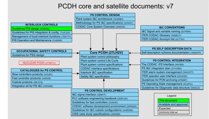
PCDH comprises a core document which presents the plant system I&C life cycle and recaps the main rules to be applied to the plant system I&Cs for conventional controls, interlocks and safety controls. Some I&C topics are explained in greater detail in dedicated documents associated with PCDH as presented in Figure 1. This document is one of them.
Core PCDH (27LH2V)
Plant system control philosophy Plant system control Life Cycle Plant system control specifications CODAC interface specifications Interlock I&C specification Safety I&C specification
PCDH core and satellite documents: v7
PS CONTROL DESIGN
Plant system I&C architecture (32GEBH) Methodology for PS I&C specifications (353AZY) CODAC Core System Overview (34SDZ5)
INTERLOCK CONTROLS
Guidelines PIS design (3PZ2D2)
Guidelines for PIS integration & config. (7LELG4) Management of local interlock functions (75ZVTY) PIS Operation and Maintenance (7L9QXR)
I&C CONVENTIONS
I&C Signal and variable naming (2UT8SH) ITER CODAC Glossary (34QECT) ITER CODAC Acronym list (2LT73V)
PS SELF DESCRIPTION DATA
Self description schema documentation (34QXCP)
CATALOGUES for PS CONTROL
Slow controllers products (333J63) Fast controller products (345X28) Cubicle products (35LXVZ) Integration kit for PS I&C (C8X9AE)
PS CONTROL INTEGRATION
The CODAC -PS Interface (34V362) PS I&C integration plan (3VVU9W) ITER alarm system management (3WCD7T) ITER operator user interface (3XLESZ) Guidelines for PON archiving (87N2B7) PS Operating State management (AC2P4J) Guidelines for Diagnostic data structure (354SJ3)
PS CONTROL DEVELOPMENT
I&C signal interface (3299VT)
PLC software engineering handbook (3QPL4H) Guidelines for fast controllers (333K4C)
CODAC software development environment (2NRS2K) Guidelines for I&C cubicle configurations (4H5DW6) CWS case study specifications (35W299) NUCLEAR PCDH (2YNEFU)
OCCUPATIONAL SAFETY CONTROLS
Guidelines for PSS design
Available and approved Expected
Legend This document
(XXXXXX) IDM ref. Guidelines PIS design (3PZ2D2)
Figure 1: PCDH documents structure
1.2 Document Scope
This document provides the guidelines to be followed by the plant system I&C designers for the hardware design of the part of the Plant System I&C which implements investment protection functions and interfaces with the Central Interlock System (CIS).
This document does not provide the guidelines to be followed by the plant system I&C designers for the configuration of the part of the PS I&C which implements the investment protection functions and interfaces with the Central Interlock Systems (CIS). These are described in Guidelines for PIS integration and configuration [RD2].
1.3 Acronyms
Table 1 shows the acronyms used in this document. The relevant acronyms have been extracted from the complete list in PCDH.
Acronym Item
3IL ITER Interlock Integrity Level ‘tril
CHD CODAC & IT, Heating & Current Drive, Diagnostics
CIN Central Interlock Network
CIS Central Interlock System
CODAC COntrol, Data Access and Communication
COTS Commercial Off-The-Shelf
CP Communication Processor
CPU Central Processing Unit
CSS Central Safety System
DLIB Discharge Loop Interface Box
I/O Input/Output
I&C Instrumentation & Control
ICS Interlock Control System
IO ITER Organization
PCDH Plant Control Design Handbook
PIN Plant Interlock Network
PIS Plant Interlock System
PLC Programmable Logic Controller
PON Plant Operation Network
PS Plant System
PSCC Plant System Conventional Control
PSH Plant System Host
PSS Plant Safety System
RO Responsible Officer
SIL Safety Integrity Level
Table 1: list of acronyms Convention:
As explained in Management of Local Interlock Functions [RD3] document, safety is a term that should not be used when describing the interlock system. Nevertheless, this term will be used in the expression “safety-related” as opposed to normal/standard.
1.4 Related documents
[RD1] Plant Control Design Handbook (PCDH) (ITER_D_27LH2V) [RD2] Guidelines for PIS integration and configuration (ITER_D_7LELG4) [RD3] Management of Local Interlock Functions (ITER_D_75ZVTY) [RD4] PIS Operation and Maintenance (ITER_D_7L9QXR)
[RD5] Central Interlock System Preliminary Design (CIS P-DDD) (ITER_D_CW5PKC) [RD6] Catalogue for I&C products – Slow controllers (ITER_D_333J63)
[RD7] Catalogue for I&C products – Cubicles (ITER_D_35LXVZ) [RD8] IO cable catalogue (ITER_D_355QX2)
[RD9] Catalogue for I&C products – Fast controllers (ITER_D_345X28) [RD10] Guidelines for I&C cubicle configurations (ITER_D_4H5DW6) [RD11] IO cabling rules (ITER_D_335VF9)
[RD12] I&C Interlock Control System – Overall Quality Plan (ITER_D_75GBSW)
[RD13] Functional specification of the I&C Cubicle Monitoring System (ITER_D_7A45LE) [RD14] Interlock Network Panel Requirements (ITER_D_4LNKHG)
[RS1] IEC 61508 Functional safety of electrical/electronic/programmable electronic safety-related systems
[RS2] IEC 61511 Functional safety – Safety instrumented systems for the process industry sector [RS3] EN 50159 Railway applications – Safety related communication on transmission systems
2 Principles
2.1 Terminology
CIS
The Central Interlock System (CIS) together with CODAC and the Central Safety System (CSS), forms the ITER I&C Central Systems. The CIS is in charge of implementing the central protection functions via the Plant Interlock Systems (PIS) and, if required, some direct actuators. It also provides access to the local interlock data of the different plant system interlocks.
PIS
The Plant Interlock Systems (PIS) are part of the plant systems I&C. Each PIS provides local protection by implementing the local interlock functions of the corresponding plant system. Most of the PIS also participate in the central interlock functions coordinated by the CIS.
All the sensors and actuators involved in machine protection in ITER are connected to at least one PIS in their plant system. The PIS constitutes the interface between the CIS and the plant systems.
Only plant systems I&C participating in inter-plant interlocks or implementing local investment protection functions are integrated in the Interlock Control System (ICS) architecture.
CIN
The Central Interlock Network provides communication between the plant interlock systems and the Central Interlock System for inter-plant systems investment protection functions.
Only plant system I&C participating in inter-plant system investment protection functions or performing local investment protection functions are connected to CIS via CIN.
PIN
The Plant Interlock Network provides communication between the components involved in the investment protection functions inside one plant system. The PIN connects the PIS in a plant system to the sensors and actuators of the same plant system. For the plant systems with more than one PIS, the PIN will also connect them together.
The Plant Interlock Network in one plant system will not be shared with other plant systems apart from the hardwired loops.
ICS
The Interlock Control System is in charge of the supervision and control of all the ITER components involved in the instrumented protection of the ITER plant systems. It comprises the Central Interlock System (CIS), the different plant interlock systems (PIS) and its networks (CIN and PIN). The ICS does not include the sensors and actuators of the plant systems but controls them through PIS.
Interlock action
These are measures or sequences of measures carried out by the CIS and/or the PIS to mitigate the risks following an interlock event. These protection actions are managed by the PIS when the measures are restricted to the plant system that generated the interlock and by the CIS when different plant systems are involved.
Interlock function
This is the logical description of the interlock actions following an interlock event. These functions are classified into two categories (see section 2.2).
Interlock event
This is the plant system state or combination of states involving different plant systems that triggers an action of the corresponding PIS and/or the CIS.
Critical interlock data
There are interlock signals performing the machine protection functions transmitted via the CIN and PIN. They can be divided into:
1. Critical Automatic Data:
- Interlock events (boolean). Example: quench.
- Interlock actions (boolean). Example: Fast Discharge Unit activation, plasma shutdown.
2. Critical Manual Data:
- Manual operation commands (boolean). Example: commands to actuators and
sensors in the case of an incident such as the loss of the control room.
- Interlock configuration data. Example: Thresholds, bypasses. Non-critical interlock data
Information treated by the PIS and the CIS which, although it is needed, does not directly participate in the interlock function. For instance, the reset (unlatch) of interlock functions, actuators and sensors, or the temperature values treated at the cryogenics PIS to decide whether the magnets can be powered or not, are used to create the Cryo_permit. However, only the Cryo_permit signal is routed to the CIS via the CIN while the temperature values are sent to CODAC via the non-secured network (see below).
Figure 2: Example of critical and non-critical data separation
2.2 Interlock function scope
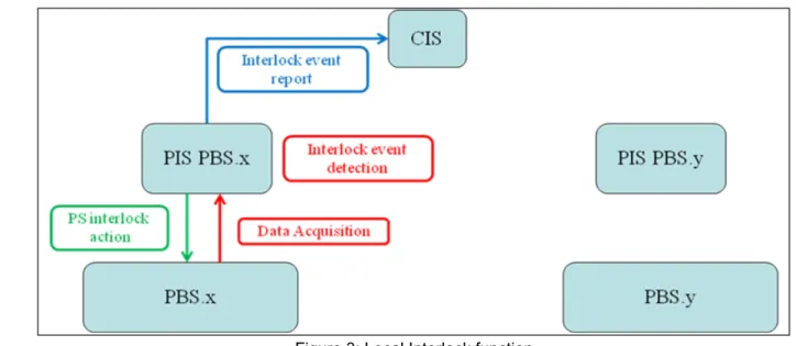
Local interlock functionThis is a machine protection function in which the interlock event and the interlock action(s) occur in the same plant system. The CIS does not play an active role in the protection function and it is only informed of the change of state of the plant system. An interlock function involving different PIS of the same plant system is considered to be a local function.
Figure 3: Local Interlock function Central interlock function
This is a machine protection function involving two or more plant systems. The interlock events are generated by the PIS and transmitted via the CIN to the CIS which takes an interlock decision and dispatches the required interlock actions to the PIS of the other plant systems involved.
Figure 4: Central Interlock function
2.3 Interlock function integrity levels
The integrity level is a functional safety profile defined for each interlock function. It is composed of a Safety Integrity Level (SIL), an inherent availability and the probability of unsolicited interlock action. The reliability and maintainability must conform to the SIL level required. The methodology to classify the machine protection functions is addressed in Management of Local Interlock Functions [RD3].
3IL-2 profile
3IL-3 profile
A 3IL-3 profile is defined with SIL3 and a minimum 99.9% inherent availability.
Distinction between CIS integrity, PIS integrity and interlock function integrity
An integrity level is specified for every interlock function. Its validation is based on a global calculation including CIS (for central functions), the PIS involved and the sensors and actuators.
The CIS integrity is the integrity level of the central standard architecture. The CIS integrity is dimensioned so that any central interlock function meets its specified integrity level.
The PIS integrity is the integrity level of the plant system standardized architecture. PIS integrity is dimensioned so that any local, central interlock function meets its specified integrity level.
2.4 Interlock function response time
Fa ul t O cc ur s Fa ul t D et ec te d Ac tio n Ta ke n
Fault Not Managed Fault Managed
Sensor detection
time
Time to React Actuator time Cushion
Process Safety Time
Pr oc es s R ea ct s H az ar do us e ve nt Activation Point Process Limit time
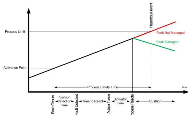
Figure 5: Time to respond to abnormal situations
The interlock system must be capable of detecting the process hazard and responding in time to prevent the hazardous event. For local functions involving only one controller this means for example, performing the following actions:
1. Sense the out-of-control condition 2. Digital filtering of input signal 3. Input process scan time 4. PLC program scan time
5. Any trip delay timers set to remove process noise must time out 6. Output process scan time
7. Digital filtering of output signal 8. Fully actuate the output device
If several controllers are involved in the interlock function (central functions or local functions involving several controllers), the communication time and the PLC program scan time for each controller must be added.
How much time the interlock system has to respond depends on the process dynamics and the conditions initiating its actions. The process safety time available for any given safeguard starts when it is required to take action and ends at the point where the event can no longer be mitigated.
The process safety time is defined as the time period between a failure occurring in the process or the basic process control system (with the potential to give rise to a hazardous event) and the occurrence of the hazardous event if the safety instrumented function is not performed.
Given the degree of uncertainty in the process safety time, the interlock system should be capable of completing its action within one-half of its allocated process safety time.
The time to react is defined for each interlock function. It determines the techniques to be used for the implementation of the function. The time to react is the time elapsed between the risk materialization and the request for mitigating action is issued.
Slow profile
If the time to react for a local function is above 200ms and 1s for a central function, standard industrial control techniques like PLCs can be used.
Fast profile
If the time to react for a local function is below 200ms and 1s for a central function, functions will be implemented by faster but more expensive and difficult to deploy techniques like FPGAs.
3 ICS Architecture
3.1 Conceptual ICS Architecture
As explained above, the ICS is formed by the Central Interlock System and the different plant interlock systems of each plant system. The ITER CODAC team is in charge of the design and implementation of the CIS through the PBS-46 (CIS) RO. The design and implementation of the PIS fall under the responsibility of the IO and Domestic Agency responsible officers for the corresponding plant system. As the person responsible of the central interlock system, the PBS-46 RO is also in charge of ensuring the proper integration of both architectures (central and local) via these guidelines.
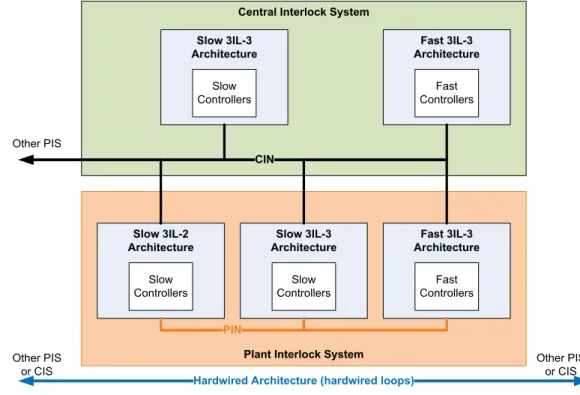
Figure 6 shows the architectures that are currently considered for the central and local architectures.
Central Interlock System Slow 3IL-3
Architecture
Fast 3IL-3 Architecture
Plant Interlock System Slow 3IL-3 Architecture Fast 3IL-3 Architecture Slow 3IL-2 Architecture CIN Fast Controllers Fast Controllers Slow Controllers Slow Controllers Slow Controllers
Hardwired Architecture (hardwired loops)
Other PIS or CIS Other PIS or CIS Other PIS PIN
Figure 6: ICS Architecture The Central Interlock System will consist of:
- Slow 3IL-3 architecture (based on PLC)
- Fast 3IL-3 architecture (based on fast controllers)
- Hardwired architecture (based on hardwired loops between plant systems)
The description of these architectures is beyond the scope of this document and is addressed in detail in the CIS Preliminary DDD [RD5].
Each plant system is connected to one or more of these central architectures via the Central Interlock Network.
Each architecture may consist of one or several controllers. Each plant system is connected to one or more of the central controllers via the Central Interlock Network.
4 PIS Architecture principles
4.1 Conceptual PIS Architecture
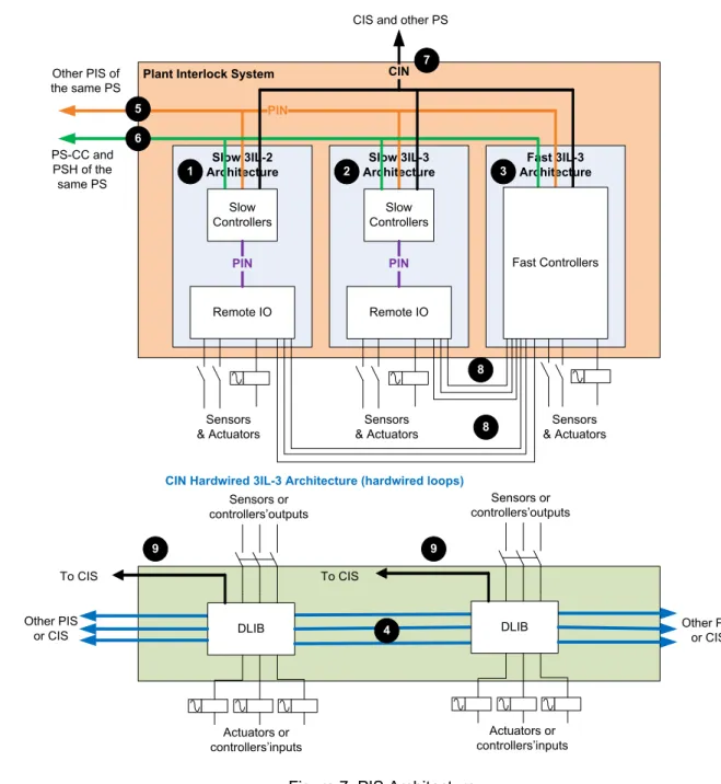
Figure 7 shows the architectures that are currently considered for the Plant Interlock System. Depending on the local and central functions that the plant system performs, one or several of these architectures may be implemented.
Plant Interlock System
Slow 3IL-3 Architecture Fast 3IL-3 Architecture Slow 3IL-2 Architecture PIN Slow Controllers Slow Controllers Remote IO PIN Sensors & Actuators Sensors & Actuators Sensors & Actuators Remote IO
CIN Hardwired 3IL-3 Architecture (hardwired loops)
Other PIS of the same PS
CIN
CIS and other PS
Other PIS
or CIS DLIB Other PIS or CIS
Sensors or controllers’outputs Actuators or controllers’inputs To CIS DLIB To CIS PS-CC and PSH of the same PS 1 2 3 4 5 6 7 8 9 9 Sensors or controllers’outputs Actuators or controllers’inputs Fast Controllers 8 PIN
Figure 7: PIS Architecture
Each Plant Interlock System is formed by one or several of the following architectures:
- Bullet 1 : Slow 3IL-2 architecture (based on PLC)
- Bullet 2: Slow 3IL-3 architecture (based on PLC)
- Bullet 3 : Fast 3IL-3 architecture (based on fast controllers)
- Bullet 4 : Hardwired architecture (based on hardwired loops inside the plant system)
The choice of the PIS architecture depends on the local and central functional analysis, the allocating rules, the process safety time of the functions and the integrity level of the functions.
Slow functions are implemented in standard slow architectures (3IL-2 or 3IL-3). Fast functions are implemented using the fast architecture based on fast controllers or a hardwired architecture based on hardwired loop. The decision to use one or other depends on the performance and the level of intelligence required by the function.
The number of different architectures inside one plant interlock system shall be kept as small as possible.
The hardwired architecture forms the only system that will directly connect components (controllers, sensors, actuators) of different plant systems, even though all actions will be surveyed by CIS (bullet 9). The number of hardwired systems must be kept to a minimum as they make inter-system standardization difficult.
Unless it is strictly necessary, only one slow architecture shall be implemented per PIS. However, architectures with different integrity levels may be found inside the same plant system when it hosts different PIS (it may be necessary to implement interlock functions in several PIS due to the application size and complexity).
Hence it is possible to implement both 3IL-2 and 3IL-3 functions in 3IL-3 architectures, whilst only 3IL-2 functions can be implemented in 3IL-2 architectures.
Even if no 3IL-3 functions are required, it is possible to implement 3IL-2 functions in a 3IL-3 architecture in order to increase availability of the system/functions. Implementing 3IL-3 architecture is also preferable if further 3IL-3 functions are identified (i.e. incorrect estimation of 3IL-2 functions).
Hence it is possible to implement functions having a slow performance requirement in fast or slow architectures, while functions requiring fast performance can only be implemented in fast architecture. Although the PIS may exchange non-critical data (i.e. signals not directly involved in the interlock chain) with the other controllers of the plant system (conventional control) and the PSH, see bullet 6, the local protection functions are carried out without any intervention from the controllers and networks apart from the PIS and PIN; and the central protection functions are carried out without any intervention from the controllers and networks apart from the PIS, the PIN, the CIS and the CIN.
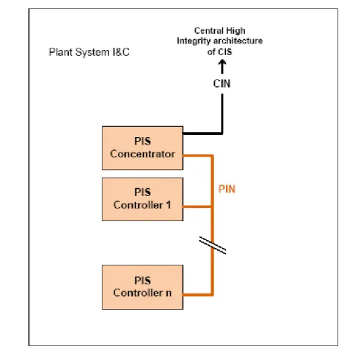
Ideally one plant system contains only one plant interlock system which is responsible for the local and central machine protection function in the plant system. The PIS controls and monitors the machine protection sensors and actuators via the plant interlock networks (PIN) and it provides the interface to the CIS via the central interlock networks (see bullet 7).
In some special cases, one plant system may host more than one plant interlock system. This is the case for plant systems with I&C procured by different Domestic Agencies or formed by components geographically separated on the site. In these cases, the protection functions may be shared among the different PIS controllers via the PIN (see bullet 5). For technological or integrity reasons, hardwired links may be considered for safety-related communication between PIS slow controllers and PIS fast controllers instead of a PIN link (see bullet 8). Whenever possible only one PIS in the plant system is connected to the CIS via the CIN. This PIS concentrator of the plant system is the single access point to CIN/CIS (see Figure 8).
Figure 8: Multiple PIS Architecture
The PIS concentrator must be chosen specifically because 3IL-2 controllers cannot be involved in 3IL-3 functions, its availability is critical for all the other PIS of the Plant Systems and it will have an impact on the response time and the integrity level of central functions. It is necessary to be careful about the PLC load because it has an impact on the PLC cycle time and about the number of connections.
4.2 Fast 3IL-3 Architecture (Fast Controllers)
This architecture may be used for local or central fast functions up to 3IL-3. Given that a few PIS will require this architecture, each PIS may have specific fast architectures. The guidelines for integration will be described in Guidelines for PIS integration and configuration [RD2]. Nevertheless, some principles should be followed:
The fast controller technology must enable 3IL-3 functions to be implemented according to the IEC standards [RS1] and [RS2] .
For the exchange of critical data, the fast controllers which are not involved in fast central functions interface with the CIS via the PIS slow architecture.
For the exchange of critical data, the fast controllers which are involved in fast central functions interface directly with the CIS fast architecture via the CIN. The use of redundant hardwired links may be considered.
The exchange of critical data directly involved in interlock functions must be done through safe protocols (keeping in mind the risks described in [RS3]), or redundant hardwired links. The exchange of critical data not directly involded in interlock functions can be done through standard protocols.
If possible, the PIS fast controllers may be connected directly to the plant system PSH and the other conventional controllers for the exchange of non-critical data within the plant system and CODAC (Bullet 6, Figure 7). Otherwise, the PIS fast controllers should interface with CODAC via PIS slow architecture for the exchange of non-critical data.
The interface between PIS fast controllers and PIS slow controllers may be done through PIN (Bullet 5, Figure 7) or redundant hardwired connections (Bullet 8, Figure 7).
When required, the PIS fast controllers should be connected to the hardwired loops connecting its I/O to a discharge loop interface box.
The PIS fast controllers may be connected to the CIS supervision tools (redundant CIS supervisor, redundant CIS engineering workstation, redundant CIS Back-up Logging System) through the CIN.
4.3 Hardwired Architecture
Depending on the interlock function requirements, some plant system controllers, sensors and/or actuators may need to be connected by a hardwired loop called a discharge loop.
Each discharge loop consists of three independent current loops that will connect one or more users in series before returning to the PLC master (CIS module). The lack of current in each of the loops will be interpreted as a false state. If at least two out of the three loops are without current, this will be interpreted by the discharge loop clients as the command to trigger a fast discharge of the circuit. In order to allow for simple and unique connectivity of all discharge loops, a dedicated user interface box called discharge loop interface box (DLIB) will be developed. This user interface box will provide a homogeneous interface to the different users for reading and acting on the discharge loops, whilst maintaining full electrical separation.
The description of this architecture is addressed in detail in the PBS-46 Preliminary DDD [RD5].
When required, the slow and fast controllers of one PIS will be connected to the hardwired loops connecting their I/O to discharge loop interface boxes.
Plant system controllers, sensors and/or actuators of one PIS must be connected to the hardwired architecture of the CIS through user interface boxes (one box per equipment).
The discharge loop is a part of the CIS. The user interface boxes and their power supplies are provided by PBS-46 but installed by the plant systems suppliers inside their cubicle near the users. The plant systems suppliers install the user interface box, the users and the power supplies and connect the users (controllers, sensors, actuators) and the power supplies to the user interface boxes. PBS-46 connects the user interface boxes together (Bullet 4, Figure 7) and monitors the discharge loops (Bullet 9, Figure 7).
4.4 Slow 3IL-3 Architecture
The slow 3IL-3 functions are implemented in a standard architecture (see Figure 9) composed of SIMATIC S7 400FH PLC, TÜV approved to SIL3. These are used in a redundant configuration to fulfil requirements relating to slow 3IL-3 functions: both CPUs are connected redundantly to all I/O modules via Profibus protocol and implementing the additional safety layer PROFIsafe. The redundant inputs or outputs are connected to different remote I/O. Whenever it is possible, hot swapping will be used. In order to keep a permanent backup of the user program on the memory card, even when power is off or when the memory card is outside the CPU, a FLASH card must be used.
Figure 9: Slow 3IL-3 Architecture
The slow 3IL-3 architecture of one PIS shall be connected to the slow 3IL-3 architecture of the CIS via safety-related protocol on Ethernet (CIN) for the exchange of critical data directly involved in interlock functions.
The slow 3IL-3 architecture of one PIS shall be connected to the slow 3IL-3 architecture of the CIS via standard protocol on Ethernet (CIN) for the exchange of critical data not directly involved in interlock functions.
The slow 3IL-3 architecture of one PIS shall be connected directly to the PSH and the plant system conventional control controllers via Ethernet (PON) for the exchange of non-critical data within the plant system and CODAC.
When required, the slow 3IL-3 architecture of one PIS will be connected to the other PIS slow architectures inside the plant system, independently of whether they are 3IL-2 or 3IL-3, using a safety-related protocol for exchanging critical data directly involved in interlock functions or using standard protocol for exchanging critical data not directly involved in interlock functions (PIN).
When required, the slow 3IL-3 architecture of one PIS will be connected to the fast controllers inside the same PIS and act as an interface between the PIS fast architecture and the CIS for the critical data,
and CODAC for the non-critical data: using a safety-related protocol or redundant hardwired links for the exchange of critical data directly involved in interlock functions; using a standard protocol for the exchange of critical data not directly involved in interlock functions.
When required, the slow 3IL-3 architecture of one PIS will be connected to the hardwired loops connecting its I/O to a discharge loop interface box.
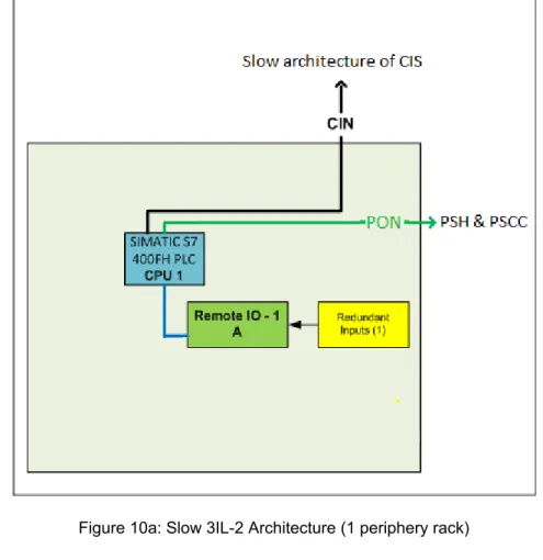
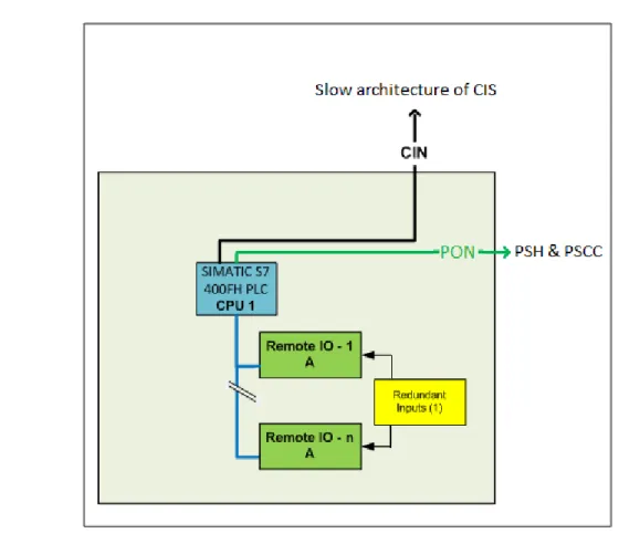
4.5 Slow 3IL-2 Architecture
The slow 3IL-2 functions are implemented in a standard architecture (see Figure 10) composed of SIMATIC S7 400FH, TÜV approved to SIL3, to fulfil requirements relating to slow 3IL-2 functions. The single CPU-H is connected to I/O modules using Profibus protocol and implementing the additional safety layer PROFIsafe. The redundant inputs or outputs are connected to different modules. In order to increase the availability of the system or if the PIS complexity (number of I/O) requires several remote I/O (peripheral racks), the redundant inputs or outputs shall be connected to different remote I/O (peripheral racks). Whenever it is possible, hot swapping must be used. A FLASH card must be used in order to keep a permanent backup of the user program on the memory card, even when power is off or when the memory card is outside the CPU.
Figure 10b: Slow 3IL-2 Architecture (several periphery racks)
The slow 3IL-2 architecture of one PIS shall be connected to the slow 3IL-3 architecture of the CIS via safety-related protocol on Ethernet (CIN) for the exchange of critical data directly involved in interlock functions.
The slow 3IL-3 architecture of one PIS shall be connected to the slow 3IL-3 architecture of the CIS via standard protocol on Ethernet (CIN) for the exchange of critical data not directly involved in interlock functions.
The slow 3IL-2 architecture of one PIS shall be directly connected to the PSH and the plant system conventional control controllers for the exchange of non-critical data within the plant system and CODAC via Ethernet (PON).
When required, the slow 3IL-2 architecture of one PIS will be connected to the other PIS slow architectures inside the plant system, independently of whether they are 3IL-2 or 3IL-3 using a safety-related protocol for exchanging critical data directly involved in interlock functions or using a standard protocol for exchanging critical data not directly involved in interlock functions (PIN).
When required, the slow 3IL-2 architecture of one PIS may be connected to the fast controllers inside the same PIS and act as an interface between the PIS fast architecture and the CIS for the critical data
of up to 3IL-2 functions only, and CODAC for the non-critical data: using a safety-related protocol or redundant hardwired links for the exchange of critical data directly involved in interlock functions; using a standard protocol for the exchange of critical data not directly involved in interlock functions.
When required, the slow 3IL-2 architecture of one PIS will be connected to the hardwired loops connecting its I/O to a discharge loop interface box.
5 Sensors & Actuators
5.1 Redundancy of Investment Protection sensors and actuators
Sensors and actuators must have the dominant failure mode to safe state or their dangerous failures must be detected (Safe Failure Fraction SFF > 60%).
To establish whether the dominant failure mode is to safe state, it is necessary to consider each of the following aspects:
- the process connection of the device,
- use of diagnostic information of the device to validate the process signal,
- use of inherent fail-safe behaviour of the device (for example, live zero signal, loss of power results in a safe state).
The minimum duration of sensor signals required for reliable detection by the fail-safe digital inputs modules of slow architectures is 30ms. This must be taken into account when choosing sensors.
Whenever it is possible, sensors and actuators involved in 3IL-2 functions should be SIL-2 or SIL-3 certified components.
Whenever it is possible, sensors and actuators involved in 3IL-3 functions or in discharge loops should be SIL-3 certified components or SIL-2 certified components able to achieve SIL-3 when used in a redundant configuration.
Whenever possible if sensors and actuators are not SIL certified components, they should be “proven in use” components. This means that a documented assessment has shown that there is appropriate evidence, based on the previous use of the component that the component is suitable for use in a safety instrumented system (refer to [RS2] IEC 61511-2 Section 11.5.3).
To limit common mode failure the choice of redundant instruments should be diversified (use of different technologies or different constructors) whenever it is possible.
Sensors and actuators involved in 3IL-2 functions shall use 2 components with a 1oo2 voting or 3 components with a 2oo3 voting in the case where there is a high risk of spurious trips or a low acceptable spurious trip rate.
In 3IL-2 architecture, redundant sensors and actuators shall be connected to different modules. If the amount of I/O requires additional peripheral racks, connection to modules on different racks should be maximized.
Sensors and actuators involved in 3IL-3 functions shall use 2 certified or “proven in use” components with a 1oo2 voting or 3 certified or “proven in use” components with 2oo3 voting in the case where there is a high risk of spurious trips or a low acceptable spurious trip rate.
Whenever it is not possible to use certified or “proven in use” sensors or actuators, sensors involved in 3IL-3 functions must use 3 components with a 1oo3 voting or 4 components with a 2oo4 voting in the case where there is a high risk of spurious trips or a low acceptable spurious trip rate.
The fail-safe digital output modules of slow architectures perform a cyclic test of the outputs. The module briefly disables the active outputs and enables the inactive outputs. The test pulses have a duration less than 1ms. High-speed actuators may briefly drop out or be activated during this test. If the process does not tolerate this action, actuators with sufficient lag (>1ms) must be used; if it is not possible, this issue can be solved duplicating the outputs (refer to 8.1.3).
5.2 Sharing of Sensors between PIS, Conventional Control and
Safety Systems
If a sensor has to be shared between the PIS and the Plant Safety System (PSS) or between the PIS and the plant system conventional control (PSCC) the preferred solution is to duplicate it (together with its redundancy) and to totally separate the systems, linking one to the PIS and the other to the PSS or the PSCC. Indeed all the components involved in an interlock function shall comply with the interlock requirement and all the components involved in a safety function shall comply with the safety requirement.
When the sensor cannot be duplicated and needs to be shared between PIS, PSS and PSCC, the preferred solution is to share the sensor between PIS and PSS and to totally separate PSCC. This allows the conventional control to be considered as a first protection layer for the process.
When the sensor cannot be duplicated and needs to be shared, two solutions are proposed:
Solution 1: The sensor is shared but the signal treatment is done separately by each system (using a signal duplicator makes the sharing of sensors transparent for each system). Example: Information from the IR is cameras treated with intelligent image processing in the diagnostics but with a reliable low-definition processor at the interlock level.
Figure 11: Sensor sharing - solution 1
Solution 2: The most critical system (i.e. the PSS for the PSS-PIS sharing and the PIS for the PIS-PSCC sharing) takes control of the sensor sharing its information via the PSS-PIS (secured) interfaces or PIS-PSCC (non-secured). Example: a quench detector connected to the interlock system whose state is sent to the conventional control of the magnet I&C.
Figure 12: Sensor sharing, solution 2
If solution 2 is chosen, it is necessary to specify the safe-state for the case of communication failures between systems (as it will be specified for PIS-CIS or PIS-PIS communication).
Whichever solution is chosen, the shared components shall comply with the requirements of each system.
Probability of failure for each solution (PFHs is the sensor part of the PFH of the function as defined above):
Solution 1:
PFHs = PFH(sensor) + PFH(signal duplicator) for each system. Solution 2:
PFHs = PFH(sensor) for the most critical system
PFHs = PFH(sensor) + PFH(most critical system) + PFH (communication between system) for the other system
If it is possible to implement a signal duplicator with a low probability of failure and which reacts quickly (compared to the sensor detection time), solution 1 is preferred.
5.3 Sharing of Actuators between PIS, Conventional Control and
Safety Systems
If an actuator has to be shared between the PIS and the Plant Safety System (PSS) or between the PIS and the plant system conventional control (PSCC) the preferred solution is to duplicate it (together with its redundancy) and to totally separate the systems, linking one to the PIS and the other to the PSS or the PSCC. Indeed all the components involved in an interlock function shall comply with the interlock requirement and all the components involved in a safety function shall comply with the safety requirement.
When the actuator cannot be duplicated and needs to be shared between PIS, PSS and PSCC, the preferred solution is to share the actuator between PIS and PSS and to totally separate PSCC. This allows the conventional control to be considered as a first protection layer for the process.
When the actuator cannot be duplicated and needs to be shared, the proposed solution is:
Solution: The actuator is shared but the command is performed separately by each system. The actuator respects the fail-safe principle, any system commanding the actuator in safe position has priority. Example: A valve can be finely regulated by the conventional control but can also be reliably set in two single states (open-closed) by the interlock (the regulation loop controlled by conventional system is opened by a safety relay controlled by interlock system: when the loop is opened, the valve goes to a safe position).
Figure 13: Actuator sharing
6 Networks
6.1 Conceptual Network Architecture
The redundant communication cables shall be kept as separate as possible althought sharing of the same cable tray is permitted.
PS0a PS0b CPU 0 C P 0 Sync 10m Sync 10m PS1a PS1b CPU 1 C P 1 Sync 10m Sync 10m FO (2m) FO (2m) PIS 1 Rack 0 PIS 1 Rack 1
To Periphery racks To Periphery racks
DP DP MAIN SWITCH BACK-UP SWITCH RJ45 RJ45 INP INP PBS.X Interlock Cubicle Bus 0 Profibus Bus 1 Profibus Bus 1 Ethernet Bus 0 Ethernet SWITCH RJ45 RJ45 Bus Ethernet Pl an t S ys te m S co pe To PON PSa PSb CPU C P a C P b To Periphery racks DP PIS 2 Rack 0 RJ45 RJ45 FO FO CIN 1 CIN 2 X 1 X 2 X 1 X 2 X 1 X 2 X 1 X 2 RJ45 PIN PIN PIN FO
Figure 14: Conceptual Network Architecture for Slow architecture TBD
Figure 15: Conceptual Network Architecture for Fast architecture
6.2 Connection between PIS and remote I/O
The connection between the PIS and its remote periphery is part of the PIN.
The communication between controllers and remote periphery shall use a safety-related protocol. Slow architectures:
In S7 F/FH Systems, the fail-safe signal modules can be operated in an ET200M distributed I/O system. Safety-related communication between the safety program in the F-CPU and the fail-safe inputs and outputs takes place via the standard PROFIBUS DP with superimposed PROFISAFE safety profile using the interface module IM-153-2 HF. In the case of 3IL-3 architecture, the Profibus network shall be redundant: each redundant CPU is connected to all the peripheral racks using 2 interface modules per rack.
Fast architectures: TBD
6.3 Connection between PIS and CIS
The connection between the PIS and the CIS is part of the CIN and it is done via the Interlock Network Panel (INP) for the architecture based on controllers and via user interface boxes for the hardwired architecture. Depending on the ability to implement safety-related protocols, exceptions can be made for connecting PIS Fast controllers to CIS Fast controllers via redundant hardwired links instead of using network attachment.
CIN is a dedicated redundant Ethernet network called CIN-P1 and CIN-P2 for interlock critical data only. Each PIS shall be connected to both CIN-P: CIN-P1 and CIN-P2.
For the architecture based on controllers, the connection between the PIS and the CIS is generally done via the Interlock Network Panel (INP). INP are installed at strategic locations close to plant system I&C cubicles. The plant system shall provide the single mode optic fibre connection up to the INP. More details about this connection are available in the Interlock Network Panel Requirements [RD14].
Slow architectures:
It must be possible for each PIS to communicate with each slow CIS module (3 CIS slow 3IL-3 modules corresponding to 6 CPU) and with each CIS supervision tool (redundant CIS supervisor, redundant CIS engineering workstation, redundant CIS Back-up Logging System).
The Central Interlock System is connected to CIN via communication processors (CPs). As communication between internal interfaces and CPs is not possible in S7 F/FH systems, each PIS shall be connected to CIN via a CP.
The safety-related communication between PIS and CIS uses the safety message frame (F_SEND/F_RCV) via S7 fault-tolerant connections between the F-CPUs.
The standard communication between PIS and CIS uses the standard message frame via S7 fault-tolerant connections.
Fast architectures: TBD
Hardwired architecture:
The connection between PIS and CIS is done via the user interface boxes. The loop connection between the user interface boxes and the network for the monitoring of the user interface boxes is provided by PBS.46. The details about the interfaces between PIS and CIS are described in Chapters 4.3 and 8.3.
6.4 Connection between different PIS in different plant systems
The direct connection between plant interlock systems belonging to different plant systems is, in principle, not allowed. The two PIS must use the CIS to exchange information.
Exceptions can be made for performance or integrity reasons (e.g. hardwired loops between plant systems). In such cases this connection between one or more PIS belonging to different plant systems is considered to be part of the CIN and therefore falls under CIS responsibility.
6.5 Connection between different PIS in the same plant system
The number of PIS inside the same plant system must be kept as low as possible and its increase can only be justified by procurement, geographical or operational reasons.
This PIS to PIS interface inside the same plant system is dedicated to the exchange of critical interlock data.
Whenever possible only one PIS of the plant system should be connected to the CIS.
In the case of the exchange of critical interlock data directly involved in interlock functions or implementation of central functions involving PIS not directly connected to CIS (this mainly concerns slow architectures), the connection between PIS must use a safety-related protocol. In addition, in the case of 3IL-3 functions, this connection must be redundant.
6.6 Connection between PIS and PON (PSH&PSCC)
The PIS or different PIS inside a plant system transmit non-critical data to the PSH which makes it available to CODAC and therefore accessible from the control rooms and to PSCC which requires it for its normal operation.
Figure 17: Connection between PIS and PSH&PSCC
The connection is done through the Ethernet PON for transmission of non-critical interlock data.
Hardwired connections are allowed for the connection PIS-PSCC but connection through PIN or CIN is not allowed: the CIN and PIN must be used for transmission of critical interlock data only.
The link between PIS and PSH must be bidirectional in order to transmit non critical commands from CODAC to PIS via the PSH and to make non critical data available from control rooms.
The link between PIS and PSCC must be unidirectional.
6.7 Connection between PIS and PSS
In principle, the network connection between PIS and PSS is not allowed. Hardwired circuits must be used to exchange information. Electrical circuits include electrical separations between the safety-class equipments (PSS) and the non-classified equipment (PIS), according to IEC 61513 and RCC-E D7540.
7 Powering
7.1 Conceptual principles
The Central Interlock System cubicles are powered by two independent sources:
- Class II-IP power supply: an uninterruptible with backup by battery set of 1 hour autonomy and by a diesel generator available for 24 hours.
- Class IV power supply: an alternative power supply in the event of class II inverter failure or fault in the class II power feeder.
The principle for powering of the PIS should be the same as for the CIS and all the PIS cubicles and components must be redundantly powered.
By mutual agreement between the Steady State Electrical Power Supply Networks and the consumer, another Class II-IP power supply can be used instead of Class IV power supply for a particular PIS. The route of the redundant powering cables should be kept as separate as possible minimizing the use of the same cable tray.
The powering of components not directly involved in investment protection, such as cubicle monitoring systems, will not have any impact on components involved in investment protection.
For powering all the recommended components, it is required to have these voltages in the cubicles:
- Class II-IP – 230Vac,
- Class IV – 230Vac,
- Class II-IP – 24Vdc,
- Class IV – 24Vdc,
The power supplies shall be monitored so that a failure of one power supply can be reported and it can be repaired in order to restore the redundant configuration in the minimum period of time. In most cases, considering that Class II-IP 24Vdc and Class IV 24Vdc are linked to Class II-IP 230Vac and Class IV 230Vac, it will be necessary and sufficient to connect Class II-IP – 24Vdc and Class IV- 24Vdc with a NC relay or switch to a digital input module.
7.2 Slow architectures
Each CPU rack shall be powered by two redundant power supplies (PS 407 AC 120/230V DC 5V / 10A for redundant use). Each power supply module shall have two backup batteries in its battery compartment (Battery Lithium AA, 3.6V/2.3 Ah).
PS0a PS0b CPU 0 C P 0 Sync 10m Sync 10m PS1a PS1b CPU 1 C P 1 Sync 10m Sync 10m FO (2m) FO (2m) PIS Rack 0 PIS Rack 1 DP DP
Class II-IP - 230Vac Class IV - 230Vac B A T T B A T T B A T T B A T T B A T T B A T T B A T T B A T T
PSa PSb CPU C P a C P b PIS Rack 0 DP Class II-IP - 230Vac
Class IV - 230Vac B A T T B A T T B A T T B A T T
Figure 19: Powering CPU racks for Slow 3IL-2 architecture
The powering of peripheral racks depends on the architecture and the number of redundant components and of its cabling on peripheral racks. It is recommended to have separate power supplies for the digital I/O and the analog inputs. The schemas below describe the redundancy concepts for peripheral racks. In the schemas below, the PS blocks are power supplies 230Vac/24Vdc and redundancy blocks are conceptual materials that enable a redundant 24Vdc supply to be implemented using 2 PS (diodes or Sitop Redundance module for example).
IM DI DO AI
DP
DI DO AI
Redundant PS – 24Vdc
PSa PSb Redundancy
Class II-IP - 230Vac Class IV - 230Vac
Figure 20: Powering 1 Periphery rack (3IL-2 architecture)
IM1a DI DO AI DP DI DO AI Redundant PS – 24Vdc IM1b DI DO AI DP DI DO AI Redundant PS – 24Vdc PSa PSb Redundancy 1
Class II-IP - 230Vac Class IV - 230Vac Redundancy 2 IM0a DP IM0b DP PSc PSd
Figure 21: Powering 2 Periphery racks
Using 2 power supplies and 1 redundancy block per rack is just one solution for creating redundant 24Vdc trains for 2 periphery racks, other solutions fulfilling redundancy requirements can be implemented.
IM1a DI DO AI DP DI DO AI Redundant PS – 24Vdc IM1b DI DO AI DP DI DO AI Redundant PS – 24Vdc IM0a DP IM0b DP IM1c DI DO AI DP DI DO AI IM0c DP Redundant PS – 24Vdc
Figure 22: Powering 3 Periphery racks
7.3 Fast architecture
TBD
7.4 Hardwired architecture
Each user interface box shall be powered by two redundant power supplies.
USER INTERFACE BOX
PSa PSb
Class II-IP - 230Vac Class IV - 230Vac
Figure 23: Powering user interface boxes (DLIB)
Each user interface box uses three redundant signals and 2oo3 voting. Exceptions can be made to allow the connection of two redundant signals and 1oo2 voting.
The following are proposals for the creation of redundant 24Vdc trains, other solutions fulfilling redundancy requirements can be implemented.
In the following solutions, it is possible to lose one power supply or one redundancy module and still operate with 2oo3 voting during the degraded period; during the degraded period, it is possible to lose one remaining power supply module or one redundancy module and still operate with 2oo3 or 1oo2 voting depending on the combination of failures.
DLIB Sensors or controllers’outputs DLIB Sensors or controllers’outputs Actuators or controllers’inputs Redundant PS – 24Vdc Redundant Train – 24Vdc Redundant Train – 24Vdc PSa PSb Redundancy 1
Class II-IP - 230Vac Class IV - 230Vac
Redundancy 3 PSc PSd Redundancy 2
PSe PSf
Figure 24: Solution 1 for powering signals for user interface boxes
DLIB Sensors or controllers’outputs DLIB Sensors or controllers’outputs Actuators or controllers’inputs Redundant PS – 24Vdc Redundant Train – 24Vdc Redundant Train – 24Vdc PSa PSb Redundancy 1
Class II-IP - 230Vac Class IV - 230Vac
Redundancy 3 PSc PSd Redundancy 2
7.5 Networks products
Each network product (switches…) involved in PIN or CIN shall be powered by two independent sources Class II-IP and Class IV.
MAIN SWITCH
BACK-UP SWITCH Class II-IP
Class IV
Figure 26: Powering network products
Network products involved in PON shall follow the recommendations of this (CODAC) network.
7.6 Other components
It is preferred that other components (monitoring system…) are redundantly powered but they can be powered by Class II-IP only.
8 Signal cabling
When signal redundancy is required, the redundant cables shall be kept as separate as possible but they may be routed through the same cable tray.
8.1 Slow architectures
It is recommended signals are connected to I/O card through terminal blocks. It is advisable to install an external protective circuit in order to provide sufficient surge strength to an ET200M with fail-safe signal modules. It is recommended that the Marshalling Terminal Assembly referenced in Catalogue for I&C products – Slow controllers [RD6] is used. It is possible to use ABB/Entrelec, UL Group or Phoenix Contact equipments as recommended in Guidelines for I&C cubicles configuration [RD10] if the equipment is certified IEC 61508 SIL3 and it is able to fulfil the reliability requirements.
8.1.1 Digital Inputs
Digital inputs modules shall be SM 326; DI 24 x DC 24V.
It is not recommended to use an external sensor supply but if it is required, the figure below shows how the sensors can be connected to an external sensor supply. All 6 channels of a channel group must be connected to the same external sensor supply. In this case, some errors cannot be detected but these errors can be met by short-circuit proof routing of the sensor lines.
Figure 27: Wiring schema of external sensor supply
For 3IL-2 functions with 1oo2 voting, two redundant sensors are each connected via one channel to the two digital modules for each process signal (1oo1 evaluation).
For SIL-2 functions with 2oo3 voting, the redundant sensors are each connected via one channel to the different digital modules (1oo1 evalution) following the same principles as with 1oo2 voting.
For 3IL-3 functions with 1oo2 voting, two redundant two-channel sensors are required per process signal. One sensor is connected via two channels to each of two opposite inputs of the digital module for each module (1oo2 evaluation).
Figure 29: Wiring schema for 1oo2 voting for 3IL-3 functions (preferred solution)
In the case of single-channel sensors, one sensor is connected via one channel to two opposite inputs of the digital module for each module (1oo2 evaluation). In general, if one sensor is connected to two inputs of the module and the module-internal sensor supply is used, the sensor supply of the left half of the module shall be used.
Figure 30: Wiring schema for 1oo2 voting for 3IL-3 functions (other solution)
For 3IL-3 functions with 1oo3, 2oo3 or 2oo4 voting, the redundant sensors are each connected via one or two channels to two opposite inputs of the different digital modules (1oo2 evaluation) following the same principles as with 1oo2 voting.
8.1.2 Analog Inputs
Analog input modules shall be SM 336; F-AI 6 x 0/4..20mA HART. This module allows 0..20mA and 4..20mA configuration. For interlock controls, the 4..20mA configuration shall be used.
The short circuit-proof internal sensor supply of the module shall be used.
The figure below shows the connections for a 2-wire transducer and for a 4-wire transducer.
For all voting schemes, each transducer shall be connected to a different module. The figure below is an example for three redundant 2-wire transducers.
Figure 32: Wiring schemas for 2oo3 voting with three redundant 2-wire transducers
8.1.3 Digital Outputs
Digital outputs modules shall be SM 326; F-DO 10 x DC 24V.
If the availability of the signal does not have to be privileged for safety reasons, the wiring scheme should use a single-channel connection for each actuator.
In this wiring scheme, if actuators respond too fast to dark period test signals, parallel wiring will suppress the dark periods. Indeed, interconnecting two opposite outputs with assigned redundancy to form a single output solves the issue. The parallel circuit in combination with an internal test coordination between the outputs 0 to 4 and 5 to 9 suppresses the 0 test pulse.
Figure 34: Wiring schemas for digital outputs for dark period suppression
If the availability of the system has to be increased for safety reasons, each actuator should be redundantly controlled by the two digital modules.
8.2 Fast architecture
TBD
8.3 Hardwired architecture
The user interface box provides a homogeneous interface to all users for reading and acting on the discharge loops.
To open the discharge loop, each user must provide three electrically independent signals to the user interface box. The user must provide a voltage in the range of 15...28V on the positive pin, whilst switching the state of the signal on the negative pin (i.e. through a dry contact…)
The user interface box will provide three electrically independent signals representing the state of the quench loop in the form of a dry contact. The user must provide a voltage in the range of 15...28V on the positive pin, whilst reading the state of the signal on the negative pin.
The connectors of the user interface box are allocated in the following way:
- One 8-pin male Burndy connector for the user for opening the discharge loop,
Pin Function 1,2 GND 3 USER 1+ 4 USER 1-5 USER 2+ 6 USER 2-7 USER 3+ 8 USER
3-Table 2: Connection diagram of connector for the user for opening the discharge loop
- One 8-pin female Burndy connector for the user for reading the discharge loop,
Pin Function 1,2 GND 3 USERSTATUS 1+ 4 USERSTATUS 1-5 USERSTATUS 2+ 6 USERSTATUS 2-7 USERSTATUS 3+ 8 USERSTATUS
3-Table 3: Connection diagram of connector for the user for reading the discharge loop
- One 12-pin male Burndy connector and One 12-pin female Burndy connector for the current loop (IN and OUT channels),
- One connector for monitoring purposes.
The 12-pin Burndy connectors and the monitoring connector are beyond the scope of the plant systems and will be connected by PBS-46.
9 Hardware
Each PIS equipment shall be compliant with its environmental constraints.
The recommendations of the providers (SAREL, Siemens…) and IO cabling rules [RD11] shall be followed.
As far as possible, cable paths prepared by Cable Trays (PBS-44) should be followed. If a path needs to be changed for any reason, then the proposed new cable path must be approved by PBS-44.
9.1 Catalogues for PIS hardware components
The cubicles hosting interlock equipment have to be chosen from the ITER Catalogue of I&C products for Cubicles [RD7].
The slow architectures for the interlock systems are based on Siemens S7 PLC. The components must be chosen from the ITER Catalogue of I&C products for Slow controllers [RD6].
The fast controllers for the interlock systems are based on TBD The components must be chosen from the ITER Catalogue of I&C products for Fast controllers [RD9].
The network equipment must fulfil the following criteria: managed switches; redundant power supply; enable ring network topology; MTBF compatible with the operational target of CIS; at least 2 optical interfaces, range of optical interface > 1km; enough electrical interfaces to connect the equipment inside the interlock cubicle (around 6 electrical interfaces).
The cables must be chosen from the ITER Catalogue for Cables [RD8].
The sensors, actuators and power supplies should be chosen to achieve the reliability (PFD/PFH criteria) and availability (MTBF criteria) requirements of the functions.
As far as possible, the PIS hardware components should be the COTS equipment that are recommended for standardization of the ITER interlock components in order to simplify the reliability, adaptability, maintenability and integration with the ICS.
The user interface boxes used for the hardwired architecture will be provided by PBS.46. Each user interface box consists of a 19” rack mounted board, having a height of 2U. The power supplies of the user interface boxes (figure 23) will be provided by PBS.46.
9.2 Spare part
In addition to the requirements set in the Plant Control Design Handbook [RD1]:
- there shall be more than 20% additional reserve ports per switch,
- there shall be more than 20% additional reserve number of connections per PLC,
- the plant systems suppliers shall provide spare parts and tools in order to replace faulty equipment within the maximum time to repair (one shift).
9.3 Cubicles
The components belonging to the Plant Interlock System are hosted in designated IP cubicles which will not be shared with conventional control or plant safety systems.
For maintenance purposes, cubicles shall be installed as far as possible in areas which are accessible during plasma operation.
The interlock cubicles located in buildings with seismic class SC1 or located in rooms with SIC cubicles are classified SC2. Other cubicles are classified NSC.
The number of interlock cubicles shall be kept as small as possible. Each architecture shall be fully implemented in a single cubicle (LCC+SCC). If several cubicles are required, it is preferred to separate slow and fast architectures.
It is recommended that the guidelines for I&C cubicle configurations [RD10] are followed.
A cubicle monitoring system is included in each I&C cubicle. Details about this system can be found in [RD13].
10 Verification and Validation
Each interlock function shall be implemented as specified taking into account identified requirements and constraints. Not only verification of compliance with its specifications, requirements and recommendations shall be performed, but also validation that these enable to achieve a sufficient functional safety.
Each plant system supplier is fully responsible for the 3IL level of its local interlock functions throughout their lifecycle as defined in the applicable standards [RS1] and [RS2] and that the system will complete its actions (in the worst case response time) within one-half of its allocated process safety time.
PBS.46 is responsible of the central interlock functions but plant systems suppliers provide part of them and they must ensure that the folowing requirements can be met. The two main requirements are interlock integrity level and response time.
As PIS event detection and PIS risk mitigation can proceed in parallel, the time to react allocated for a central function can be divided in 3 parts.
CIS PIS detecting events
Sensor detection time PLC time Comm. time
PIS mitigating risk
PLC time Actuator time
PLC time Comm. time PIS detecting events
Sensor detection
time
PLC time
PIS mitigating risk
PLC time Actuator time
Figure 36: PST validation of central function
As all the PIS event detection and all the PIS risk mitigation must be taken into account when calculating the 3IL level of a central function, the 3IL level allocated for a central level has to be divided into as many parts as there are in the PS involved in the function.
CIS PIS detecting events
Sensor PFH/PFD PLC PFH/PFD CIN PFH/PFD
PIS mitigating risk
PLC PFH/PFD Actuator PFH/PFD PLC PFH/PFD CIN PFH/PFD PIS detecting events
Sensor PFH/PFD
PLC PFH/PFD
PIS mitigating risk
PLC PFH/PFD
Actuator PFH/PFD
Figure 37: 3IL validation of central function
The CIS will probably participate in 15% of the 3IL-3 functions and so 1.5% of the 3IL-2 functions. Each plant system must provide the documentation concerning its part of the interlock function (functions specification, organic and functional analysis, justification of “proven in use” components, calculations for SIL compliance, FAT report, response time validation in the worst case response time, SAT report, datasheets, user/maintenance manual and procedures…) as described in I&C interlock Control System – Overall Quality Plan [RD12].