A system for marker-less human motion estimation
B. Rosenhahn1,4, U. G. Kersting2, A. W. Smith2, J. K. Gurney2, T. Brox3, and R. Klette1
1
Computer Science Department,2Department of Sport and Exercise Science The University of Auckland, New Zealand
Math. Image Analysis Group, Saarland University, Germany
4
From November 2005: Max Planck Center Saarbr ¨ucken,[email protected]
In Pattern Recognition, Springer LNCS 3663, W. Kropatsch, R. Sablatnig, and A. Hanbury (Eds.), pp. 230-237, Vienna, Austria, Aug. 2005 °c Springer-Verlag Berlin Heidelberg 2005
Abstract. In this contribution we present a silhouette based human motion
es-timation system. The system components contain silhouette extraction based on level sets, a correspondence module, which relates image data to model data and a pose estimation module. Experiments are done in a four camera setup and we estimate the model components with 21 degrees of freedom in two frames per second. Finally, we perform a comparison of the motion estimation system with a marker based tracking system to perform a quantitative error analysis. The results show the applicability of the system for marker-less sports movement analysis.
1
Introduction
Human motion estimation from image sequences means to determine the rigid body motion [11] and joint angles of a 3D human model from 2D image data. Due to redun-dancies multi-view approaches are necessary. Often simplified models are used, e.g. by using stick, ellipsoidal, cylindrical or skeleton models [1, 9, 7]. We recently introduced an approach for silhouette based human motion estimation [14] which uses free-form-surface patches to estimate the pose and joint angles of the upper torso. In [15] we further applied local and global morphing techniques to get realistic motions of the up-per torso model. These basic modules are now extended to a complete human motion estimation system. The system consists of an advanced image segmentation method, dynamic occlusion handling and kinematic chains of higher complexity (21 degrees of freedom). Finally we perform a comparison of the system with a commercial marker based tracking system [10] used to analyze sports movements1. We perform and ana-lyze exercises, such as push ups or sit ups. The algorithm proves as stable, robust and fairly accurate.
The contribution is organized as follows: We will start with the basic setup of the motion capture system. Then we will continue with the system modules. Here we will briefly describe image segmentation based on level sets, pose estimation and the dy-namic occlusion handling to deal with partial occlusion in certain frames. The next section presents the experimental results and the quantitative error analysis followed by a brief discussion.
1
Motion Analysis Corporation is one of the leading provider of optical motion capture sys-tems in entertainment, video-games, film, broadcasting, virtual reality, medicine, sports, and research.
2
The human motion tracking system
A 3D object model builds the a priori knowledge of the system, which is in this case given as two free-form surface patches with two kinematic chains. Each kinematic chain
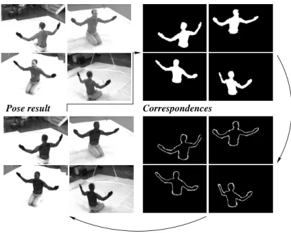
Pose result Correspondences Extracted Silhouettes Input Image
Fig. 1. The capture system consists of iterating the following steps: Segmentation,
correspon-dence estimation, pose estimation.
consists of seven joints (three for the shoulder, two for the elbow and two for the wrist). Furthermore we added one back segment joint to the torso surface patch. The estimation procedure is dealing with 21 unknowns, six for the pose parameters (three for rotation and three for translation), 7 for each arm and one backbone joint. During correspon-dence estimation (along four frames) we collect around 5000 point corresponcorrespon-dences (slightly varying dependent on the visible information) and still track in two frames per second for the four camera sequence. Using the 3D model and four images from a (trig-gered) calibrated camera sequence, the motion tracking system consists of three main components, namely silhouette extraction, matching and pose estimation. All compo-nents are iterated to stabilize segmentation on the one hand and pose estimation on the other hand.
2.1 Image segmentation
Image segmentation usually means to estimate boundaries of objects in an image. This task can become very difficult, since noise, shading, occlusion or texture information
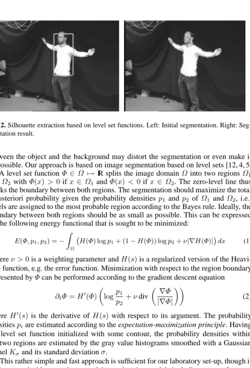
Fig. 2. Silhouette extraction based on level set functions. Left: Initial segmentation. Right:
Seg-mentation result.
between the object and the background may distort the segmentation or even make it impossible. Our approach is based on image segmentation based on level sets [12, 4, 5, 2]. A level set functionΦ ∈Ω 7→ IR splits the image domainΩinto two regionsΩ1 andΩ2withΦ(x)> 0ifx∈ Ω1andΦ(x) < 0ifx ∈ Ω2. The zero-level line thus marks the boundary between both regions. The segmentation should maximize the total a-posteriori probability given the probability densitiesp1 andp2 of Ω1 andΩ2, i.e., pixels are assigned to the most probable region according to the Bayes rule. Ideally, the boundary between both regions should be as small as possible. This can be expressed by the following energy functional that is sought to be minimized:
E(Φ, p1, p2) =− Z Ω ¡ H(Φ) logp1+ (1−H(Φ)) logp2+ν|∇H(Φ)| ¢ dx (1)
whereν >0is a weighting parameter andH(s)is a regularized version of the Heavi-side function, e.g. the error function. Minimization with respect to the region boundary represented byΦcan be performed according to the gradient descent equation
∂tΦ=H0(Φ) µ logp1 p2 +νdiv µ ∇Φ |∇Φ| ¶¶ (2) whereH0(s)is the derivative of H(s) with respect to its argument. The probability densitiespiare estimated according to the expectation-maximization principle. Having the level set function initialized with some contour, the probability densities within the two regions are estimated by the gray value histograms smoothed with a Gaussian kernelKσand its standard deviationσ.
This rather simple and fast approach is sufficient for our laboratory set-up, though it is also conceivable to apply more elaborated region models including texture features. Figure 2 shows an example image and the contour evolution over time. As can be seen, the body silhouette is well extracted, but there are some deviations in the head region, due to the dark hair. Such inaccuracies can be compensated from the pose estimation procedure. For our algorithm we can make a tracking assumption. Therefore, we ini-tialize the silhouette with the pose of the last frame which greatly reduces the number of iterations needed. The implementation is fast; the algorithm needs 50 ms per frame and 200 ms image processing time for a four-camera setup.
2.2 Pose estimation
For pose estimation we assume a set of point correspondences(Xi, xi), with 4D (homo-geneous) model pointsXiand 3D (homogeneous) image pointsxi. Each image point is reconstructed to a Pl¨ucker lineLi= (ni, mi), with a (unit) directionniand moment
mi[11].
Every 3D rigid motion can be represented in an exponential form
M= exp(θξˆ) = exp µ ˆ ω v 03×1 0 
whereθξˆis the matrix representation of a twistξ= (ω1, ω2, ω3, v1, v2, v3)∈se(3) =
{(v, ω)|v∈IR3, ω∈so(3)}, withso(3) ={A∈IR3×3|A=−AT}.
In fact,M is an element of the one-parametric Lie group SE(3), known as the group of direct affine isometries. A main result of Lie theory is, that to each Lie group there exists a Lie algebra which can be found in its tangential space, by derivation and evaluation at its origin; see [11] for more details. The corresponding Lie algebra to
SE(3)is denoted as se(3). A twist contains six parameters and can be scaled toθξ with a unit vectorω. The parameterθ∈IR corresponds to the motion velocity (i.e., the rotation velocity and pitch). For varyingθ, the motion can be identified as screw motion around an axis in space. To reconstruct a group actionM ∈SE(3)from a given twist, the exponential functionexp(θξˆ) =M ∈SE(3)must be computed. This can be done efficiently by using the Rodriguez formula [11],
exp(ˆξθ) = µ exp(θωˆ) (I−exp(ˆωθ))(ω×v) +ωωTvθ 01×3 1 ¶ , forω6= 0
withexp(θωˆ)computed by calculating
exp(θωˆ) =I+ ˆωsin(θ) + ˆω2(1−cos(θ)).
Note that only sine and cosine functions of real numbers need to be computed. For pose estimation we combine the reconstructed Pl¨ucker lines with the screw representation for rigid motions and apply a gradient descent method: Incidence of the transformed 3D pointXiwith the 3D rayLican be expressed as
(exp(θξˆ)Xi)3×1×ni−mi= 0.
Indeed,Xiis a homogeneous 4D vector, and after multiplication with the4×4matrix
exp(θξˆ) we neglect the homogeneous component (which is1) to evaluate the cross product with ni. We now linearize the equation by usingexp(θξˆ) = P∞k=0(θk!ξ)ˆk ≈
I+θξˆ, withIas identity matrix. This results in
((I+θξˆ)Xi)3×1×ni−mi= 0
and can be reordered into an equation of the formAξ =b. Collecting a set of such equations (each is of rank two) leads to an overdetermined system of equations, which can be solved using, for example, the Householder algorithm. The Rodriguez formula can be applied to reconstruct the group actionM from the estimated twist ξ. Then
the 3D points can be transformed and the process is iterated until the gradient descent approach converges.
Joints are expressed as special screws with no pitch of the formθjξˆj with known
ˆ
ξj(the location of the rotation axes as part of the model representation) and unknown joint angleθj. The constraint equation of ajth joint has the form
(exp(θjξˆj). . .exp(θ1ξˆ1) exp(θξˆ)Xi)3×1×ni−mi= 0
which is linearized in the same way as the rigid body motion itself. It leads to three linear equations with the six unknown pose parameters andj unknown joint angles. Collecting a sufficient number of equations leads to an overdetermined system of equa-tions.
Note, that since we work with reconstructed 3D lines, we can gain equations from different cameras (calibrated with respect to the same world coordinate system) and put them together in one system of equations and solve them simultaneously. This is the key idea to deal with partial occlusions: A joint which is not visible in one camera must be visible in another one to get a solvable system of equations. A set of four cameras around the subject covers a large range and allows to analyze quite complex motion patterns.
2.3 Correspondence estimation
After image segmentation correspondences between the object model and the extracted silhouettes are established. Therefore, we follow a modified version of an ICP algorithm [14] and use a voting method to decide, whether a point belongs to the torso or one of the arms. These correspondences are applied on the pose estimation module resulting in a slightly transformed object. This is used to establish new correspondences until the overall pose converges.
3
Experiments
A lack of many studies is that only a visual feedback about the pose result is given, by overlaying the pose result with the image data, e.g. [14]. To enable a quantitative error analysis, we use a commercial marker based tracking system for a comparison. Here, we use the Motion Analysis software [10], with an 8-Falcon-camera system. For data capture we use the Eva 3.2.1 software and the Motion Analysis Solver Interface 2.0 for inverse kinematics computing [10]. In this system a human has to wear a body suit and retroflective markers are attached to it. Around each camera is a strobe light led ring and a red-filter is in front of each lens. This gives very strong image signals of the markers in each camera. These are treated as point markers which are reconstructed in the eight-camera system. The system is calibrated by using a wand-calibration method. Due to the filter in front of the images we had to use a second camera set-up which provides real image data. This camera system is calibrated by using a calibration cube. After calibration, both camera systems are calibrated with respect to each other. Then
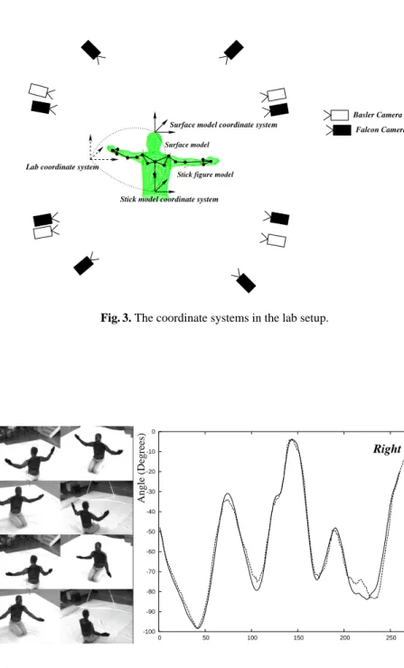
Surface model
Stick figure model
Stick model coordinate system
Surface model coordinate system
Lab coordinate system
Basler Camera Falcon Camera
Fig. 3. The coordinate systems in the lab setup.
-100 -90 -80 -70 -60 -50 -40 -30 -20 -10 0 0 50 100 150 200 250 300 Right Elbow Frame Angle (Degrees)
Fig. 4. Tracked arms: The angle diagrams show the elbow values of the Motion analysis system
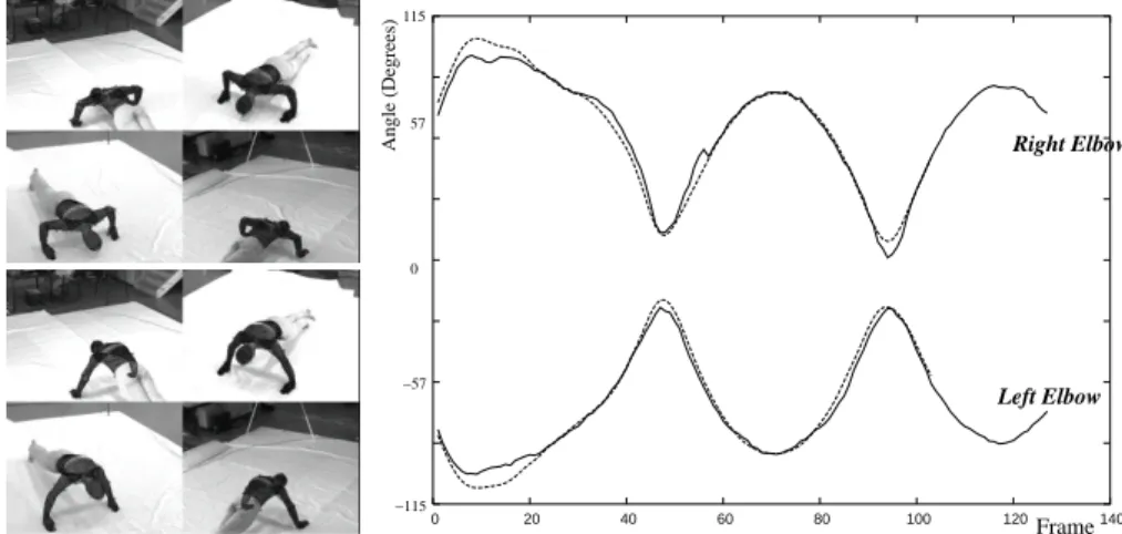
-2 -1.5 -1 -0.5 0 0.5 1 1.5 2 0 20 40 60 80 100 120 140 Right Elbow Left Elbow Frame 0 −115 −57 57 115 Angle (Degrees)
Fig. 5. Tracked Push-ups: The angle diagrams show the elbow values of the Motion analysis
system (dotted) and the silhouette system (solid).
we generate a stick-model from the point markers including joint centers and orienta-tions. This results in a complete calibrated set-up we use for a system comparison. It is visualized in figure 3.
The images in the upper left of figure 1 show the body-suit with the attached mark-ers. These lead to minor errors during silhouette extraction, which are omitted here. Figure 4 shows the first test sequence, where the subject is just moving the arms for-wards and backfor-wards. The diagram on the right side shows the estimated angles of the right elbow. The marker results are given as dotted lines and the silhouette results in solid lines. The overall error between both angles diagrams is 2.3 degrees, including the tracking failure between frames 200 till 250.
Figure 5 shows the second test sequence, where the subject is performing a series of push-ups. Here the elbow angles are much more characteristic and also well com-parable. The overall error is 1.7 degrees. Both sequences contain partial occlusions in certain frames. But this can be handled from the algorithm.
4
Discussion
The contribution presents a human motion estimation system. The system extracts sil-houettes by using level-set functions and uses a model with 21 degrees of freedom in a four-camera set-up. Finally we perform a comparison of the marker-free approach with a commercial marker based tracking system. In [13] eight bio-mechanical mea-surement systems are compared (including the Motion Analysis system). There is also performed a rotation experiment which shows, that the RMS2errors are typically within three degrees. Our error measures fit in this range quite well.
Marker-less human motion tracking is highly challenging for sports, exercise and clinical analysis and the system evaluation shows, that our approach is leading in the
2
right direction for a marker-less stable and accurate human motion estimation system. Future works will continue with silhouette extraction in more complex environments, so that we can also analyze sports movements in non-lab environments.
Acknowledgments
This work has been supported by the DFG grants RO 2497/1-1 and RO 2497/1-2.
References
1. Bregler C. and Malik J. Tracking people with twists and exponential maps. IEEE Computer
Society Conference on Computer Vision and Pattern Recognition, Santa Barbara, California,
pp. 8-15, 1998.
2. Brox T., Rousson M., Deriche R., Weickert J. Unsupervised segmentation incorporating colour, texture, and motion In Computer Analysis of Images and Patterns, Springer LNCS 2756, N.Petkov, M.A.Westenberg (Eds.), pp. 353-360, Proc. CAIP 2003 Conference, Gronin-gen, The Netherlands, 2003.
3. Campbell R.J. and Flynn P.J. A survey of free-form object representation and recognition techniques. Computer Vision and Image Understanding (CVIU), Vol. 81, pp. 166-210, 2001. 4. Caselles V., Catt´e F., Coll T. and Dibos F. A geometric model for active contours in image
processing. Numerische Mathematik, 66:1–31, 1993.
5. Chan T. and Vese L. An active contour model without edges. In M. Nielsen, P. Johansen, O. F. Olsen, and J. Weickert, editors, Scale-Space Theories in Computer Vision, volume 1682 of Lecture Notes in Computer Science, pages 141–151. Springer, 1999.
6. Cremers D., Kohlberger T., and Schn¨orr Ch. Shape statistics in kernel space for variational image segmentation. Pattern Recognition, No. 36, Vol. 9, pp. 1929-1943, 2003.
7. Fua P., Pl¨ankers R., and Thalmann D. Tracking and modeling people in video sequences.
Computer Vision and Image Understanding, Vol. 81, No. 3, pp.285-302, March 2001.
8. Gavrilla D.M. The visual analysis of human movement: A survey Computer Vision and
Image Understanding, Vol. 73 No. 1, pp. 82-92, 1999.
9. Mikic I., Trivedi M, Hunter E, and Cosman P. Human body model acquisition and tracking using voxel data International Journal of Computer Vision (IJCV), Vol. 53, Nr. 3, pp. 199– 223, 2003.
10. Motion Analysis Corporationwww.motionanalysis.comlast accessed February 2005.
11. Murray R.M., Li Z. and Sastry S.S. A Mathematical Introduction to Robotic Manipulation.
CRC Press, 1994.
12. Osher S. and Sethian J. Fronts propagating with curvature-dependent speed: Algorithms based on Hamilton–Jacobi formulations. Journal of Computational Physics, Vol.79, pp. 12-49, 1988.
13. Richards J. The measurement of human motion: A comparison of commercially available systems Human Movement Science, Vol. 18, pp. 589-602, 1999.
14. Rosenhahn B., Klette R. and Sommer G. Silhouette based human motion estimation.
Pat-tern Recognition 2004, 26th DAGM-symposium, T¨ubingen, Germany, C.E. Rasmussen, H.H.
B¨ulthoff, M.A. Giese, B. Sch¨olkopf (Eds), LNCS 3175, pp 294-301, 2004, Springer-Verlag Berlin Heidelberg.
15. Rosenhahn B. and Klette R. Geometric algebra for pose estimation and surface morphing in human motion estimation Tenth International Workshop on Combinatorial Image Analysis
(IWCIA), R. Klette and J. Zunic (Eds.), LNCS 3322, pp. 583-596, 2004, Springer-Verlag
Berlin Heidelberg. Auckland, New Zealand,
16. Zang Z. Iterative point matching for registration of free-form curves and surfaces.