Installation Instructions
–
Shaper 1800 aircraft cable installation
Installation Instructions
–
Shaper 1800 aircraft cable installation
Installation Instructions
–
Shaper 1800 aircraft cable installation
IMPORTANT: Read carefully before installing fixture. Retain for future reference.
GENERAL: Upon receipt of the fixture, thoroughly inspect for any freight damage which should be brought to the attention of the delivery carrier. Compare the catalog description listed on the packing slip with the fixture label on the housing to assure you have received the correct material.
SAFETY: This fixture must be wired in accordance with the National Electrical Code and applicable local codes and ordinances. Proper grounding is required to insure personal safety. Carefully observe grounding procedure under installation section.
APPLICATIONS: This lighting fixture is designed for outdoor lighting services, and should not be used in area of limited ventilation or inside high ambient temperature enclosures. It must be stored in a dry location prior to installation. Do not expose lighting fixture to rain, dust or other environmental conditions prior to installation and insertion of photo control or shorting cap (if so equipped). Do not install the fixture near combustible materials or locate next to airflow blocking surfaces within 6 inches. Best results will be obtained if installed and maintained according to the following recommendations.
WARNING
Make Certain Power is OFF before starting installation or attempting any maintenance.
WARNING
Risk of Fire/Electric Shock. If not qualified, consult an electrician.
WARNING
Risk of Electric Shock – Disconnect power at fuse or circuit breaker before installing or servicing.
WARNING
Risk of Personal Injury – Fixture may become damaged and/or unstable if not installed properly.
● Do not mount luminaire within 6” of a combustible
surface.
● Do not handle luminaire by the glass. Do not touch
LEDs.
WARNING
Risk of Burn – Disconnect power and allow fixture to cool before servicing.
ote:
N These instructions do not claim to cover all details or variations in the equipment, procedure, or process described, nor to provide directions for meeting every possible contingency during installation, operation or maintenance. When additional information is desired to satisfy a problem not covered sufficiently for user’s purpose, please contact your nearest representative.
ote:
N This lighting fixture has been shipped complete with one of several mounting options. Please follow the installation instructions specific to the catalog part that you ordered.
ote:
N Care must be taken not to set lighting fixture down on optical lenses or lift the fixture in the lens area.
ote:
N Specifications and dimensions subject to change without notice.
ote:
N Ensure adequate structure to support luminaire weight.
DOME
Shade/ ShapeRLM
A B
INSTRUCTIONS:
1. Make sure power is off.
2. Remove Shade and inspect Product Label.
3. Align the holes on the Shade along with the Grippers (Fixture Side) and secure with Coupler. 4. Using the provided screws, secure the Mounting Plate unto the J-Box (provided by others).
5. Pull the Grippers (Ceiling Side) through the Aircraft Cables as shown and secure the Grippers on to the Mounting Bracket.
6. Place the Canopy through the AC Cord and make sure the holes are aligned as shown. 7. Push the AC Cord into the Grippers on the fixture side and set the height of the fixture. 8. Pull the SJ Cord through the Canopy and through the Mounting Bracket.
9. Strain Relief the SJ Cord unto the Canopy Plate.
10. Using U.L. approved wire connectors: connect the neutral (white) wire to the supply neutral, connect the luminaire line wire (black) to the supply line wire, connect the ground (green) wire to the supply ground.
11. Push all wire into the J-box can mount the Cover Bracket using 2x 8-32 screws. 12. Turn power on to test installation.
13. Raise Canopy flush to ceiling and secure with 2x Set Screws.
Canopy Cover Canopy Aircraft Cable Set Screw SJ Cord Strain Relief Gripper Canopy Plate Detail B Scale 1 : 1.5 Gripper Nipple Shade Trim
Side View Isometric View Coupler
3 COOPER LIGHTING SOLUTIONS IL525014EN Installation instructions
Figure 1.
Figure 2.
Figure 3.
INSTRUCTIONS:
1. Make sure power is Off.
2. Remove Shade and inspect Product Label.
Shade
Coupler Product Label
Shade Gripper (Fixture Side)
3. Align the holes on the Shade along with the Grippers (Fixture Side) and secure with Coupler.
4. Using the provided screws, secure the Canopy Plate
Make Sure The Holes Are Aligned Figure 6. Figure 7. Figure 5. Canopy Plate Canopy AC Cord Grippers (Ceiling Side)
Grippers Aircraft Cables
5. Pull the Grippers (Ceiling Side) through the Aircraft Cables as shown and secure the Grippers on to the
Canopy Plate.
6. Place the Canopy through the AC Cord and make sure the holes are aligned as shown.
7. Push the AC Cord into the Grippers on the fixture side and set the height of the fixture.
5 COOPER LIGHTING SOLUTIONS IL525014EN Installation instructions
Figure 8. Figure 9. Figure 10. Figure 11. SJ Cord Canopy
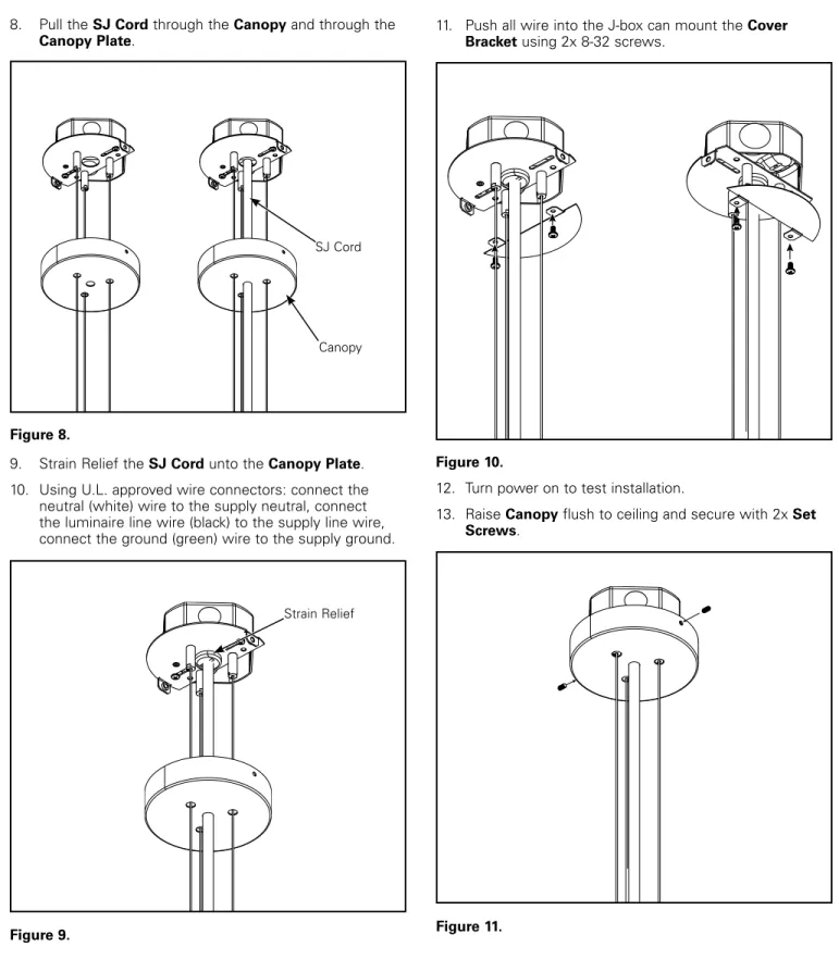
8. Pull the SJ Cord through the Canopy and through the
Canopy Plate.
9. Strain Relief the SJ Cord unto the Canopy Plate. 10. Using U.L. approved wire connectors: connect the
neutral (white) wire to the supply neutral, connect the luminaire line wire (black) to the supply line wire, connect the ground (green) wire to the supply ground.
Strain Relief
11. Push all wire into the J-box can mount the Cover Bracket using 2x 8-32 screws.
12. Turn power on to test installation.
13. Raise Canopy flush to ceiling and secure with 2x Set Screws.
Cooper Lighting Solutions
Cooper Lighting Solutions is a registered trademark. All trademarks are property
Garanties et limitation de responsabilité
Veuillez consulter le site www.cooperlighting.com pour obtenir les conditions générales.