IOP Conference Series: Materials Science and Engineering
PAPER • OPEN ACCESS
Development of Vertical Articulated Robot Deburring System by Using
Sensor Feedback
To cite this article: Hiroki Kakoi et al 2020 IOP Conf. Ser.: Mater. Sci. Eng. 886 012035
View the article online for updates and enhancements.
10th TSME-International Conference on Mechanical Engineering (TSME-ICoME 2019) IOP Conf. Series: Materials Science and Engineering 886 (2020) 012035
IOP Publishing doi:10.1088/1757-899X/886/1/012035
Development of Vertical Articulated Robot Deburring System
by Using Sensor Feedback
Hiroki Kakoi1*, Kiyoshi Yanagihara2, Koji Akashi2 and Kensuke Tsuchiya3, 1Department of Creative Engineering, National Institute of Technology, Ariake College, 150 Higashihagio-Machi, Fukuoka, 836-8585, Japan
1Faculty of Creative Engineering, National Institute of Technology, Ariake College, 150 Higashihagio-Machi, Fukuoka, 836-8585, Japan
2Institute of Industrial Science, The University of Tokyo, Komaba4-6-1 Megur-ku, Tokyo, 153-8505, Japan
* Corresponding Author: [email protected]
Abstract
Demand of customer for higher quality of product is increasing. Number of skilled engineers, however, is chronically lacking in worldwide. Thus, the change of environment of production drives robotization of hand-finishing process recently. This study is about Robotization of deburring by means of a hand grinder, which is one of the hand finishing tools. Basically, in robotization of the hand-finishing process, teaching operation is selected for the programming of the tool path of the robotic arm. In this study, however, a vertically articulated robot equipped with various sensors is developed for the robotic deburring system, the feasibility of fully automated robotic deburring by using hand grinder is investigated.
Keywords: industrial robot, computer vision, depth camera
1. Introduction
At the early stage of robot deburring study, Proctor F. M., et. al. (1989) developed the hand-finishing by utilizing industrial robot [1]. In their study, the technology which is a robot splaying and trimming is tried. Such technologies are being studied and evolved continuously until now. In the studies, teaching process which one of the robot programing methods is used to input move-path to the robot.
Regarding an industrial robot, its moves and positionings are important because they affect the accuracy directly [2] [3]. In order to teach tool path, there are various studies [4] [5] [6] including offline teachings, such as [7] [8] [9] [10] [16] concerning auto programing system using Computer Aided Design (CAD) data of workpiece, and Thomessen T, et.al . developed a method[14] that the workpiece geometry is pre-scanned by using force censor which is installed in the end of robot hand to generate grinding paths automatically.
10th TSME-International Conference on Mechanical Engineering (TSME-ICoME 2019) IOP Conf. Series: Materials Science and Engineering 886 (2020) 012035
IOP Publishing doi:10.1088/1757-899X/886/1/012035
2
that utilizes camera and image processing technology; the other is the one, which utilizes force sensor [14-26].
Verl, et al. (2019) reviewed trends and problems of utilization of industrial robot in recent years [26]. This review predicts that industrial robot will be applied not only for transferring of the workpiece but also machining including deburring here after, the application must increase. Needless to say, that the goal of development of robot deburring system is a fully automated one that not only enables removing burrs but also recognizes burrs without any teaching for the robot.
Along the trend, Naoki et al. had been developed a deburring robot system since 1980s [7]. They integrated the state of art components of those days into a robot deburring system, which included the sensor, the computer, the software, and so on. The applied components, however, was relatively expensive in those days. Thirty years on the environment of the development of robot, deburring system has become lowering the cost by providing high-speed network and sensors such as camera technology.
In this study, we develop a new deburring robot system using image processing technology and newly developed displacement sensor, which is using optical technology. The system, however, is different from previous studies. It relies on data not from CAD, but from image processing and displacement sensors for a deburring simple bar of a square in cross-section.
In the designing of robotic deburring system, our surveillance about previous study found that those studies are categorized by 4 technical components as shown in Table 1. Teaching means a necessity to program arm trajectory manually for a robot controller. Sensor feedback means whether the robot system equipped with sensors to detect the state of the deburring process. Target application means the production process to which robot deburring is applied.
Table 1. components listed from previous studies
Category of Componen Selected unselected
Teaching Not Necessary Necessary
Sensor feedback Equipped Not equipped
Handling object by End effector Tool Work
Target application Edge burr by milling Bead by welding, Fin by casting
Since our consideration from table1. We select teaching less method. The method do not need for human hands. It is important to use a computer for complete automation. A sensor that makes decisions on behalf of humans is needed.
Regarding the workpiece and tools installation, there are two ways. Either mounting the workpiece on the robot hand or mounting the deburring tool on the robot hand must be selected. For mounting the workpiece on the robot hand, it is too difficult to hold a heavy and large workpiece because of the ability of utilized robot. On the other hand, mounting deburring tool such as hand grinder is easy because the tool is light and the size is regulated. Therefore setting the deburring tool on the robot hand as the end effector is selected.
In the experiment, burr is produced on the edge of workpiece with milling. This burr, what we call “edge burr”, is dealt as a target.
There are several similar robot systems. [27][28] In these researches, a camera is used as a sensor for the sensor fusion. We used a depth camera and a force sensor instead of a camera.
In this paper, an outline of the developed robotized deburring system and experimental result of detection of tool contact is reported by using the sensing system, which is composed of image processing and force feedback.
10th TSME-International Conference on Mechanical Engineering (TSME-ICoME 2019) IOP Conf. Series: Materials Science and Engineering 886 (2020) 012035
IOP Publishing doi:10.1088/1757-899X/886/1/012035
2. System configuration
2.1 set-ups
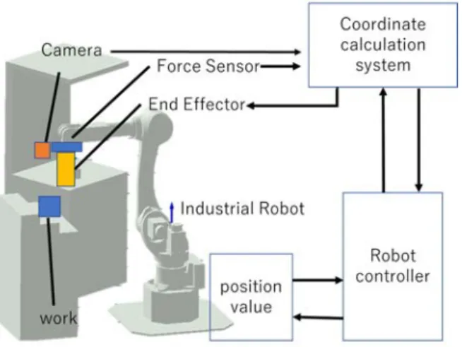
Figure 1. System configuration
The developed system is shown in Figure 1. The system consists of an arm robot (Kawasaki Heavy Industry Co. Ltd. RS20N), a workpiece recognition system by using image capturing, and a coordinate calculation system to generate toolpath. A router with a fixed abrasive tool is attached to the robot for deburring. For the recognition system, a depth camera (Intel Realsense D435) is installed on the tip of the arm of the robot.
The installation of various sensors and routers at the end of the robot and the coordinate system of the sensors are shown in Figure 2.
The value of the force sensor increases when a force is applied in each axis of the arrow direction. It can measure not only the forces of x, y, and z-axis, but also the torque around those three axes. The obtained torque of x, y, and z axis is labeled rx, ry, and rz, respectively. Clockwise and left-hand rules are applied to view from the front of each axis.
Figure 2. Hand tools and origin of work
10th TSME-International Conference on Mechanical Engineering (TSME-ICoME 2019) IOP Conf. Series: Materials Science and Engineering 886 (2020) 012035
IOP Publishing doi:10.1088/1757-899X/886/1/012035
4
image. The calculated path data is sent to the robot controller, the controller commands the robot to move arm along to the programmed path. The coordinate calculation system also monitors not only distance data from the depth camera but also the value of force sensor in the deburring process. If the value excesses the programmed threshold level, the coordinate calculation system corrects the tool path in processing.
3. Experiment
3.1 Measurement of shape and position of the workpiece by using a depth camera
The goal of development of this deburring system is to produce tool paths automatically by using sensor feedback that consists of the depth camera and the force sensor without any teaching of the robot controller.
Regarding tool motion in deburring, it is considered that the robot arm is programmed to trace the outside edge of a workpiece with a fixed abrasive tool. In order to realize the idea, it is necessary to obtain the distance between the tool and the workpiece, and the top shape of its surface.
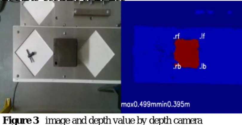
Both left and right images in Figure 3 are camera images each of which shows, the distance output of depth sensors, respectively. In this experiment, the square top shape of the work piece is selected, and it is fixed in keeping parallel to the position of the outside shape of the table. Those images demonstrate that it is possible to obtain the outer shape of the work and the distances between the depth sensor and the top surface of the workpiece. Distance value measured by depth camera has potentially 2% of error. Therefore, for precision deburring, more accurate detection of tool position is needed to determine the original position of the tool.
Figure 3. image and depth value by depth camera
3.2 The Influence of vibration of router rotation on force sensor value
In order to aid the limitation of accuracy of the depth camera, the utilization of the force sensor is mentioned in the previous section. The output of the force sensor, however, can be influenced by the rotational vibration of the router. Thus, the influence is investigated by recording the output of the sensor with or without rotation of the router. Table 2 shows the dispersion of the force sensor output. The dispersion of rotation y-axis is 13.7 when the router turns off. Meanwhile, it is 265 when the router turns on. From the results, it is determined that the torque value of ry is utilized for monitoring because it is relatively easy to distinguish the difference between on and off.
10th TSME-International Conference on Mechanical Engineering (TSME-ICoME 2019) IOP Conf. Series: Materials Science and Engineering 886 (2020) 012035
IOP Publishing doi:10.1088/1757-899X/886/1/012035
3.3 The experiment detecting touch-down of the tool by utilising sensor fusion
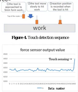
In order to detect touch-down of the tool onto the workpiece, following the experimental sequences, as shown in figure 4, is developed for an experiment. In this sequence, firstly the shape of the workpiece is recognized by using the depth camera. Then the tool is rapidly approached to upward position of 5 mm. from the surface of the work. Thirdly, the tool is fed at relatively low speed of feed while referring ry value of torque of y-axis of the force sensor.
In the sequence, the torque threshold must be programmed to the robot controller before the operation.
After the command is given to the robot arm to move tool, the robot controller gets the value of the force sensor with the move of every 0.03 mm. If the output value becomes equal to or greater than the set threshold value, the robot arm is held and then the original tool position is programmed on the controller.
Figure 5 shows sensor output values of ry when the touch down of tool is recognised and the origin is programmed according to the sequence. In this experiment, the distance of free run of the tool from detection to stop is 0.03 mm.
Figure 4. Touch detection sequence
Figure 5. Change in the output shaft torque value ry
4. Conclusion
The feasibility of fully automated robotic deburring by using hand grinder with the sensor feedback system was investigated in this study. The goal of development of robotic deburring system not only can automatically program tool movement without any motion teaching of robot, but also can provide appropriate modification to the path in processing. A work recognition system and a tool path generation system was developed by using a depth camera, also a router with a fixed abrasive was created too as an end effector was utilized for deburring. The results obtained from the
system-10th TSME-International Conference on Mechanical Engineering (TSME-ICoME 2019) IOP Conf. Series: Materials Science and Engineering 886 (2020) 012035
IOP Publishing doi:10.1088/1757-899X/886/1/012035
6
(1) To realise fully automated teaching-less robot deburring system, a combination of the depth camera and the force sensor is employed for sensor feedback controlling system.
(2) By utilizing the depth camera, not only capturing the front shape of the workpiece but also measuring the distance to the edge of the workpiece object are available. The acquired image of work shape and the measured distance can also be useful for path generation of the robot movement.
(3) In the experiment to detect touchdown of the tool by using the distance data measured by the depth camera and the feedback from the force sensor’s results demonstrate that the system can detect the distance between the tool and the surface of the workpiece within less than 0.30 mm.
How to distinguish the burr from the edge of the workpiece by using the captured image and positioning data of the edge, and how to make a tool to approach to the edge are subjects for further studies.
Acknowledgments
The use of vertically- articulated robot for this study is provided by Prof. Akashi of NITA, and the helpful assistance of Takaya Matsumura, our lab colleague, is greatly appreciated..
A part of this work was supported by a research grant of AMADA FOUNDATION.
References
[1] Proctor F M Norcross R J and Murphy K N 1989 Technical Paper SME 89–138 [2] Song H C Kim B S and Song J B 2012 Proc. IEEE/ASME Int Conf on Adv Intelligent
Mechatronics 890–895
[3] Dietz T Schneider U Barho M Oberer-Treitz S Drust M and Hollmann R and Hägele M 2012
Proc. VDE 7th German Conf on Robotics Proceedings of ROBOTIK 1–6
[4] Solvang B Sziebig G and Korondi P 2008 Proc. IEEE Int Conf on Networking, Sensing and
Control 949–954
[5] Bi Z and Kang B 2014 Enterprise Information Systems 8(2) 225–245 [6] Park S C and Chung Y C 2003 Computer-Aided Design 35(5) 467–475
[7] Asakawa N Itoh K and Takeuchi Y 1998 Journal of the Japan Society for Precision Engineering
64 (5)
[8] Toda K Asakawa N and Takeuchi Y 1999 JSME (65-631) 1288–1294
[9] Gary M B and Mohamed A E 1994 IEEE Trans. On Industrial Electronics (41-2) 137–146 [10] Nonaka Y Sakaue S Yanagihara Y and Yokoshima K 1995 Proc. IEEE Int. Conf. Robotics
Autom 2084–2090
[11] Asada H and Izumi H 1989 IEEE Trans on Robotics and Automation 5(2) 166–173 [12] Zhang H Chen H Xi N Zhang G and He J 2006 Intelligent Robots and Systems 9–15 [13] Shimokura K Asada H and Liu S 1996 Robotics Society of Japan 14(1) 144
[14] Thomessen T Elle O J Larsen J L Andersen T Pedersen T Pedersen J E and Lien T K 1992 Proc.
of the 23th Int. Symposium on Industrial Robots 457–464
[15] Jinno M Ozaki F Yoshimi T Tatsuno K Takahashi M Kanda M Tamada Y and Nagataki S 1995
Proc. 1995 IEEE Int. Conf. on Robotics and Automation1455–1460
[16] Kuss A Drust M and Verl A 2016 Proc. 49th CIRP Conference on Manufacturing Systems 57
8–13
[17] Wang X Wang Y and Xue Y 2006 Proc. IEEE Int Conf on Industrial Informatics 921–925 [18] ] Robertsson A Olsson T Johansson R Blomdell A Nilsson K and Haage M 2006 Proc. IEEE/RSJ
Int Conf on Intelligent Robots and Systems 2743–2748
[19] Pagilla P R and Yu B 2001 Proc. IEEE American Control Conference 1 630–635
[20] Elbestawi M A Tuen K M Srivasava A K and Dai H 1991 Annals of the CIRP 40(1)391–394 [21] Kashiwagi K 1991 J. Robotics Society of Japan 9(3) 94–98
[22] Kazerooni H Bausch J J and Kramer B M 1986 ASME J. Dynamic Systems Measurement
10th TSME-International Conference on Mechanical Engineering (TSME-ICoME 2019) IOP Conf. Series: Materials Science and Engineering 886 (2020) 012035
IOP Publishing doi:10.1088/1757-899X/886/1/012035
[23] Her M G and Kazerooni H 1991 ASME J. of Dynamic Systems Measurement and Control 113
60–66
[24] Ling H C and Li C F 1997 Proc. IEEE Int. Conf. Robotics Autumn meeting 2844–2849 [25] Muto S and Shimokura K 1997 J. Robotics Society of Japan 15(5)744–751
[26] Verl A Valente A Melkote S Brecher C Ozturk E and Tunc L T 2019 CIRP
Manufacturing Technology 68 799–822
[27] Aasakawa N and Kiriyama Y 2011 JSME 77 782