On Using Weather Information for Efficient Remote Data
Collection in WSN
∗Woochul Kang, John A. Stankovic and Sang H. Son
Department of Computer ScienceUniversity of Virginia
{wk5f|stankovic|son}@cs.virginia.edu
ABSTRACT
Even though real-time data access to remote sensor data is desirable for many WSN applications, collecting remote data reliably from a WSN is a challenging task since many components of the WSN are subject to harsh elements of nature. A deployed system’s performance and lifetime can be impaired if this harsh environment of the deployment site is not considered. The deployments of LUSTER, a WSN for ecological monitoring, show that weather has significant im-pact on the connection availability between a WSN and a back-end. In this paper, we show how the weather of the deployment site can affect the performance of LUSTER, the connection to the back-end in particular. In addition, we propose a weather-aware delay-tolerant networking scheme in the context of LUSTER. Our trace-driven simulation re-sult shows that despite the inaccuracy of the weather infor-mation and the simplicity of the algorithm, the sensor data transmission failure rate can be reduced significantly.
Categories and Subject Descriptors
C.2.4 [Computer-Communication Networks]: Distributed applications
General Terms
Design, Experimentation, Performance
Keywords
Wireless sensor network, deployment, delay-tolerant network-ing, directional antenna, weather
1.
INTRODUCTION
Wireless sensor networks often have to be deployed in re-mote locations with limited access. Some deployment areas might be accessible only once in several months [5]. In such situations, one of the biggest advantages of using a WSN
∗
This research work was funded in part by NSF-CNS-0614886.
Permission to make digital or hard copies of all or part of this work for personal or classroom use is granted without fee provided that copies are not made or distributed for profit or commercial advantage and that copies bear this notice and the full citation on the first page. To copy otherwise, to republish, to post on servers or to redistribute to lists, requires prior specific permission and/or a fee.
EmNets’08, June 2-3, 2008, Charlottesville, Virginia, USA
Copyright 2008 ACM 978-1-59593-694-3/07/06 ...$5.00.
compared to traditional out-door data collection schemes is that a WSN can enable real-time live data acquisition from the remote site. For example, an environmental scientist can analyze data in real-time without having to wait for the next trip to the deployment site. One of the key requirements to achieve this capability is having a reliable network connec-tion between the remote WSN and a back-end node through the Internet. However, having a reliable connection to the remote deployment site is a challenging task since WSNs are often deployed in remote areas geographically separated from fixed communication infrastructures. Without stable communication links, the network connectivity is often lost or highly intermittent. In addition, in-network data storage can be very limited thereby leading to losing important data. In such remote areas, using a long-range wireless communi-cation device that can reach a nearest communicommuni-cation infras-tructure is required. For example, a satellite communication link or high-gain directional antennas can be considered. Delay/disruption-tolerant networking (DTN) [4] techniques have been proposed to overcome the limitation of current WSN technology in such intermittently available communi-cation networks. DTN implements a store-and-forward ap-proach, in which continuous end-to-end connectivity is not required. Even though the DTN approach addresses how to transfer data from sensors to a destination in such in-termittently available networks, its reactive approach can still waste significant communication bandwidth and power since data lost in-transit must be retransmitted, sometimes many times. We show that a proactive approach that pre-dicts connection availability and quality can dramatically decrease the chance of in-transit data transmission failures and subsequent retransmissions.
In this paper, we propose a proactive DTN approach in the context of LUSTER (Light Under Shrub Thicket for Envi-ronmental Research) [7]. Our solution exploits weather in-formation to predict the availability and quality of the con-nection to the back-end. The proposed weather-aware DTN in LUSTER obtains weather information of the deployment area from the back-end server and controls when to send sensor readings to the back-end. In the future, in network weather sensors will be added to increase the accuracy of the predictions.
Our experiences of deploying LUSTER to Hog island (a re-mote and uninhabited island), Virginia, provide experimen-tal evidence that the communication link is highly
! " # !$ % "" & &' & & ( " # !$ ) &* " ( + , -. / 0 "1 !
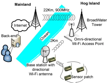
Figure 1: LUSTER deployment in Hog Island.
ble to the weather at the deployment site, and the impact of the weather can not be completely removed mechanically. In LUSTER, a high-gain directional Wi-Fi antenna of a base station provides an interface to an omni-directional Wi-Fi antenna at 2km-distance. Wind gusts shake the antenna face even though it has a small wind load area and is supported by firm supports. As we show by actual data from the is-land this movement causes frequent communication failures to the back-end. We also show by preliminary simulation results that exploiting the weather information can reduce the data transmission failures significantly.
The outline of the paper is as follows. In Section 2, we give an overview of the deployment environment and the original DTN design of LUSTER. In Section 3, we present the impact of the weather on the connectivity between the WSN and the Internet in the LUSTER system. In Section 4, we present a weather-aware DTN, which demonstrates that weather information can be exploited to improve the performance of WSNs. Trace-driven simulation results are presented to support our claim. Section 4 concludes the paper and discusses future work.
2.
OVERVIEW OF LUSTER
LUSTER is an ecological monitoring WSN that targets help-ing scientists understand the light dynamics in shrub thick-ets and its consequences. LUSTER enables on-site ecologi-cal data collection using custom-built large-capacity storage nodes as well as on-line data collection and access through a back-end server. The LUSTER architecture is a cluster of nodes, in which each cluster has nodes in a one-hop commu-nication range. The clusters operate on separate frequency channels to prevent interference with the neighboring clus-ters.
In this section, we give a short overview of the deployment environment and the original DTN design of LUSTER.
2.1
Deployment Environment
The deployment location of LUSTER is Hog Island, which is located off the Eastern Shore of Virginia. Access to the deployment site is highly limited since reaching the site
re-quires considerable driving, boating, and hiking. To provide a real-time data access capability to environment scientists, a communication network as shown in Figure 1 was installed for LUSTER deployment. A Crossbow Stargate, which is at-tached to the base station, acts as the gateway between the WSN and a 2kmWi-Fi omni-directional access point. Due to the long distance, a high-gain directional Wi-Fi antenna is used with a Stargate to reach the Wi-Fi omni-directional antenna. The Wi-Fi access points lose power at night since they are solar-powered. The access points operate only from 9:30AM to 4:30pm. This situation necessitates the use of DTN techniques in LUSTER.
2.2
DTN in LUSTER
In LUSTER, the DTN technology is used to increase the reliability, particularly when connections to the gateway or the back-end server are lost. The connection unreliability is caused mainly because of the scheduled down time of the Wi-Fi access points and the weather.
Unlike typical bundle protocol-based DTN [4], the DTN in LUSTER uses dedicated storage nodes that overhear the communication between sensor nodes in a cluster and the base station. A storage node at each cluster has relatively large flash memory space (2GB) to store the overheard sen-sor values. The overhearing avoids the cost of explicit ra-dio traffic between sensors and storage nodes. Even when the connection to the back-end is lost, the sensor values are stored in the storage nodes reliably. LUSTER uses a reac-tive approach for DTN, in which the back-end detects the loss of sensor data and requests the lost data to the stor-age nodes using a query on historical data. Since sensors of LUSTER monitor and transmit data periodically to the back-end, the back-end can detect the loss of sensor data. Upon reception of a query, the storage node retrieves the data from its buffer in main-memory or flash memory, and transmits it to the back-end via the base station. This re-active DTN places the responsibility in the back-end, and it allows each application to control the quality-of-data in an application-specific manner.
3.
THE EFFECT OF WEATHER
One of the major problems found in LUSTER was the unre-liable connection to the back-end due to the the directional Wi-Fi antenna. Even though we fixed the antenna with 3-point poles to reduce the effect of wind as shown in Figure 2-(a), the wind gust easily bent the the antenna support within a few hours or days, breaking the connection to the back-end permanently. Eventually, we changed the antenna to the one that has a small wind-load area as shown in Figure 2-(b) and provided more robust physical support. With this modifica-tion, we reduced the effect of wind and it has provided the connection to the back-end for more than 2 months with-out permanent disconnections. However, many intermittent disconnections were still observed due to weather.
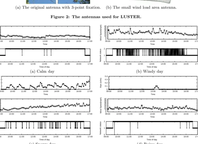
For example, we have monitored both the weather status of Hog Island and the connection status to the back-end for more than 2 months. Each subgraph of Figure 3 shows the weather conditions between 9am and 5pm at the deployment site and the corresponding network connection status to the back-end at the same time. For brevity, only weather fac-tors that are believed to have the strongest potential impact
(a) The original antenna with 3-point fixation. (b) The small wind load area antenna.
Figure 2: The antennas used for LUSTER.
0 5 10 15 20 25 30 35 40 09:00 10:00 11:00 12:00 13:00 14:00 15:00 16:00 17:00 Wind Speed(mph) Time 0 5 10 15 20 25 30 35 40 09:00 10:00 11:00 12:00 13:00 14:00 15:00 16:00 17:00 Wind Speed(mph) Time 0 1 2 09:00 10:00 11:00 12:00 13:00 14:00 15:00 16:00 17:00 Network status Time of day 0 1 2 09:00 10:00 11:00 12:00 13:00 14:00 15:00 16:00 17:00 Network status Time of day
(a) Calm day (b) Windy day
0 0.1 0.2 0.3 0.4 09:00 10:00 11:00 12:00 13:00 14:00 15:00 16:00 17:00 Snow (in/hr) Time 0 0.1 0.2 0.3 0.4 09:00 10:00 11:00 12:00 13:00 14:00 15:00 16:00 17:00 Rain (in/hr) Time 0 5 10 15 20 25 30 35 40 09:00 10:00 11:00 12:00 13:00 14:00 15:00 16:00 17:00 Wind Speed(mph) Time 0 5 10 15 20 25 30 35 40 09:00 10:00 11:00 12:00 13:00 14:00 15:00 16:00 17:00 Wind Speed(mph) Time 0 1 2 09:00 10:00 11:00 12:00 13:00 14:00 15:00 16:00 17:00 Network status Time of day 0 1 2 09:00 10:00 11:00 12:00 13:00 14:00 15:00 16:00 17:00 Network status Time of day
(c) Snowy day (d) Rainy day
Figure 3: Weather conditions and network status.
are shown for each observation. The wind speeds (miles per hour) and the precipitation level (inches per hour) of snow and rain are measured every 6 minutes. In the network sta-tus graphs, a value of 2 represents when the WSN is reach-able from the back-end, a value of 1 represents when the WSN is not reachable, but the connection to the East Shore is available from the back-end, and a 0 represents when the Internet connection is not available at the back-end. Figure 3-(a) shows a typical day that has no harsh weather conditions, e.g., rain, snow or wind. In such a calm day, the connection status is reliable with 99.8% average connection availability. On the contrary, Figure 3-(b) shows a day when the average wind speed is higher than 20mphand frequent wind gusts happen. As shown in the figure, the connec-tion is highly vulnerable to the wind, degrading the average network availability to less than 48% during the day. This low network availability is caused by the vulnerability of the
Wi-Fi directional antenna to the wind.
In a directional antenna, as the gain of the antenna increases, the angle of radiation usually decreases [3]. This provides a greater coverage distance, which is required for most WSNs, but with a reduced coverage angle. Due to this reduced an-gle, even a small movement of the face of directional anten-nas can cause a high deviation of the coverage area at long distances. In practice, since antennas can not be installed densely in most WSN deployment scenarios due to the cost, stealthiness, and other reasons, each antenna should cover long distances, making directional antennas inherently vul-nerable to wind. We may consider using an omni-directional antenna to overcome this situation. However, omni direc-tional antennas consume more power and are less stealthy. Therefore, it is not always a feasible option.
rain, snow, and fog when the operating frequency band is less than 11GHz[6], and our observation verifies that rain has negligible effect on the radio communication as shown in Figure 3-(d).1 However, we found that the snow has
non-negligible effect on the connection status as shown in Figure 3-(c). This is because even though the snow does not atten-uate the radio signal itself, the build-up of snow on the face of the antenna degrades the sensitivity of the antenna [2].
4.
WEATHER-AWARE DTN IN LUSTER
As discussed in the previous section, the impact of weather can not be completely removed in real deployments for lots of practical reasons such as cost and harsh remote environ-ments. In LUSTER, the high vulnerability of the connection to the back-end to wind can severely degrade the perfor-mance of the WSN. In this section, we present a weather-aware DTN algorithm in LUSTER, and show its perfor-mance improvement using a simulation study. An extension to this simple solution is also discussed.
4.1
Weather-Aware DTN
In LUSTER, delay-tolerant networking is achieved by ex-tra in-network storage nodes that ex-transmit lost data to the back-end when data loss is detected at the back-end. For in-stance, any loss of data due to a lost connection is detected at the back-end and a request query is sent to the storage nodes when the connection becomes available. However, an unreliable connection to the back-end due to bad weather conditions, wind in particular, can cause many transmis-sion failures, and subsequent retransmistransmis-sions. Preventing these high rates of transmission failures is critical since those transmission failures incur high power consumption for com-munication, for flash memory operations on both the stor-age nodes, and the base station, and extra processing at the gateway. This high power consumption is directly related to the lifetime of the system. To overcome the effect of this frequent disconnection problem due to wind, the DTN al-gorithm for storage nodes are modified as in Alal-gorithm 1.
Algorithm 1: DTN algorithm at a storage node.
Input: wind level information for nextτ periods
whilehave requested data from back-end do
if predicted wind level of next period< αthen
transmit the data;
else
wait until next period;
end end
The information regarding the predicted wind level is pro-vided from the back-end to the storage nodes periodically. If a storage node has data to transmit to the back-end, it transmits the data only when predicted wind level is lower than the thresholdα, instead of transmitting immediately. The parameters of the Algorithm 1,τandα, make trade-offs between accuracy, cost, and effective bandwidth. The accu-racy of the weather prediction information is determined
1Wi-Fi’s operating frequency band is 2.4
GHz. 0 10 20 30 40 50
Feb/03 Feb/04 Feb/05 Feb/06 Feb/07 Feb/08 Feb/09 Feb/10
Wind Speed (mph)
Time
(a) Wind level of the week.
0 0.5 1
Feb/03 Feb/04 Feb/05 Feb/06 Feb/07 Feb/08 Feb/09 Feb/10
Failure Ratio
Time
(b) Failure ratio without weather information.
0 0.5 1
Feb/03 Feb/04 Feb/05 Feb/06 Feb/07 Feb/08 Feb/09 Feb/10
Failure Ratio
Time
(c) Failure ratio with weather information (α= 15mph).
0 0.5 1
Feb/03 Feb/04 Feb/05 Feb/06 Feb/07 Feb/08 Feb/09 Feb/10
Failure Ratio
Time
(d) Failure ratio with weather information (α= 10mph).
Figure 4: Exploiting Weather Information.
by τ. If τ is short, then the weather information is more accurate. However, it requires more frequent communica-tion to update the weather informacommunica-tion. On the contrary, the effective bandwidth of the system is determined by the wind-level threshold α. An effective bandwidth is defined asphysical bandwidth×connection availability.2 A small
wind-level threshold decreases the availability of the con-nection to the Internet, reducing the effective bandwidth of the system. An application should consider if the effective bandwidth is enough to transmit sensor data to the back-end without causing unlimited increase of the sback-ending queue at the storage nodes.
In the algorithm, the accuracy of the weather information from a back-end may be low and the weather information may not reflect the actual weather situation at the exact location of the deployment site since the publicly available weather services provide only coarse-grained weather infor-mation both temporally and spatially. In the future, we plan on adding a weather sensor such as wind-level sensor in the system itself and running a predictive model locally to have better understanding of the weather situation at the exact location of the deployment site. However, this on-site weather information acquisition requires additional cost for sensing and computation.
4.2
Simulation
The purpose of this simulation is to show that even coarse grain weather information can be used effectively to reduce the number of transmission failures due to network unavail-ability.
The simulation setting is similar to the real LUSTER
deploy-2In LUSTER, the physical bandwidth for sensor data
wind threshold (α) connection availability effective bandwidth
∞ 0.22 154 bytes/sec
15mph 0.161 112.7 bytes/sec 10mph 0.101 70.7 bytes/sec
Table 1: α’s and effective bandwidths (Physical bandwidth= 700 bytes/sec).
ment. 5 sensor nodes each with 7 light sensors generate a total 70 bytes of data every second and transmit this date to a local base station. Storage nodes overhear the transmission and store the data in flash memory as backup to the real-time data transmission. The physical bandwidth for sensor data transmission is 700 bytes/second. As a metric for com-parison, the failure ratios for every 10 minutes are observed for 7 days, from February 3rd, 2008 to February 9th, 2008. The failure ratio is defined as # lost packets
# total sent packets. The
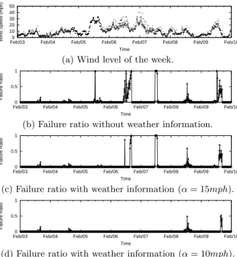
connec-tion status between the base staconnec-tion and the back-end for the 7 days is the trace obtained from the 3rd LUSTER de-ployment. Since a detailed weather prediction for the period is not available, we use the weather history of the Hog island for the the same period [1]. To simulate the inaccuracy of the weather prediction, an error component is introduced to the observed wind level withN ormal(0, 2 mph). The final predicted wind levels are provided to the storage nodes. Figure 4 shows the simulation results. Figure 4-(b) shows the failure ratio for the 7 days when the weather informa-tion is not used in transmitting the lost data to the back-end. The system shows high failure ratios when the wind level is high; for example, February 5th, 6th, and 9th. The aver-age failure ratio for the 7 days is 0.24, meaning 1 out of 4 messages is dropped due to the unexpected network discon-nection. In Figure 4-(c) and (d), when the predicted wind levels are provided, the failure ratio are reduced to 0.184 and 0.054, respectively forα= 15mphand α= 10mph. How-ever, the effective bandwidth is reduced whenαis small as shown in Table 1. For example, whenα= 10mph, the ef-fective bandwidth is 70.7 bytes/second, barely satisfying the minimum bandwidth requirement of the application, which is 70 bytes/second.
In summary, this evaluation shows the benefit of exploiting the weather information even though the weather informa-tion is a publicly available coarse grained one, and the DTN algorithm is very simple.
5.
CONCLUSION AND FUTURE WORK
In an ideal lab environment, we simply ignore the effect of the harsh environment at the deployment site. How-ever, if a system is built only for ideal situations, its sur-vivability can be endangered in a real deployment. From the repeated real deployments to Hog island, we found that weather can be a serious factor that can determine the per-formance and the lifetime of the system. In particular, the connection availability to the back-end with directional an-tenna is highly vulnerable to wind. In most real deploy-ments, using high gain directional antenna is inevitable to achieve a long range communication distance, making the system vulnerable to wind conditions at the deployment site. Alternatives to connect a WSN to the Internet includes using omni-directional antennas and satellite antennas. However,
these alternatives also have their own problems. For exam-ple, even though satellite communication is more resilient to wind, other weather conditions including rain, snow, and fog have a non-negligible impact on its communication fre-quency band, 3 GHz - 22 GHz. This shows that a weather factor can not be completely removed in real deployments. Through a trace-driven simulation, we showed that a sys-tem can suffer from a high transmission failure ratio if the wind-factor is not considered. The high transmission failure ratio can incur significant power consumption for retrans-missions, severely decreasing the lifetime of the system. In the weather-aware DTN, the data transmission failure ratios are reduced significantly, even with publicly available coarse-grained weather information. As far as we know, this is the first work exploiting weather information at the deployment site to improve the performance of deployed WSNs. Due to the relatively short period of the deployment to ob-serve diverse weather patterns, we could not make a defini-tive conclusion how other weather conditions affect the per-formance of the WSN. However, our observation shows that snow might have some impact on the performance of Wi-Fi antennas even though it’s 2.4 GHz radio frequency band is known to be resilient to snow. We need further work on this issue to better understand how other weather conditions affect the performance of the WSN.
6.
REFERENCES
[1] ”weather underground,”
http://http://www.wunderground.com.
[2] J. Y. Cheah. Wet antenna effect on vsat rain margin.
IEEE Transactions on Communications, 41(8):1238–1244, 1993.
[3] Z. N. Chen, editor.Antennas for portable Devices. John Wiley & Sons, 2007.
[4] K. Fall. A delay-tolerant network architecture for challenged internets. InSIGCOMM ’03: Proceedings of the 2003 conference on Applications, technologies, architectures, and protocols for computer
communications, pages 27–34, 2003.
[5] K. Martinez, J. K. Hart, and R. Ong. Environmental sensor networks.Computer, 37(8):50–56, 2004. [6] A. D. Panagopoulos, P. M. Arapoglou, and P. Cottis.
Satellite communications at ku, ka, and v bands: propagation impairments and mitigation techniques.
IEEE Communications Surveys and Tutorials, 6(3):2–14, 2004.
[7] L. Selavo, A. Wood, Q. Cao, T. Sookoor, H. Liu, A. Srinivasan, Y. Wu, W. Kang, J. Stankovic, D. Young, and J. Porter. Luster: wireless sensor network for environmental research. InSenSys ’07: Proceedings of the 5th international conference on Embedded networked sensor systems, 2007.