Concurrent Engineering Workflow
CONFLOW - a project funded by the Commission of the European Communities under the INCO-Copernicus programme (project no. 960243)
Partners:
• Technische Universität Clausthal, Germany
• University of Wales Cardiff, United Kingdom
• Mummert + Partner Unternehmensberatung AG, Hamburg, Germany
• University of Rousse, Bulgaria
• Technical University of Budapest, Hungary
• ZITA Ltd, Rousse, Bulgaria
Mechanisms Required to Enable Concurrent
Engineering Workflow
Authors:
Dr. Krastimir Popov, Daniela Tsaneva, Kalin Karadjov, Katalina Grigorova, Plamenka Hristova
University of Rousse
Deliverable No.: 2.4 Document No.: CONFLOW.98.01
SUMMARY...4
1 INTRODUCTION...5
2 STRUCTURE MANAGEMENT ...6
2.1 DEFINITION...6
2.2 DESCRIBING THE PRODUCT STRUCTURE USING BOM ...6
2.2.1 BOM definition ...6
2.2.2 BOM in SAP R/3 ...7
2.2.3 BOM in Pro/Engineer and Pro/INTRALINK ...8
2.2.3.1 Pro/INTRALINK structure management...8
2.2.3.2 Structure management in Pro/Engineer ...11
2.2.4 Structure definition of Manometric Thermoregulator using SAP R/3 ... 12
2.3 DESCRIBING THE PRODUCT STRUCTURE USING CAD MODEL...17
2.3.1 CAD model in AutoCAD ... 18
2.3.2 CAD model in Pro/Engineer ... 21
2.4 MECHANISM ENABLING THE INTEGRATION OF BILL OF MATERIALS AND CAD MODEL...30
3 CONFIGURATION MANAGEMENT... 32
3.1 CONFIGURATION MANAGEMENT DEFINITION...32
3.2 REASONS FOR A CONFIGURATION MANAGEMENT SYSTEM...35
3.3 OBJECTIVES OF A CONFIGURATION MANAGEMENT SYSTEM...35
3.4 INGREDIENTS FOR A CMS...35
3.4.1 Configuration Identification... 35
3.4.2 Configuration Status Accounting ... 35
3.4.3 Configuration Control ... 35
3.5 CONFIGURATION MANAGEMENT IN DIFFERENT SYSTEMS...36
3.5.1 Metaphase Series 2 ... 36 3.5.2 Optegra ... 37 3.5.3 Sherpa/IPD ... 37 3.5.4 Pro/ENGINEER ... 37 3.5.5 Pro/INTRALINK ... 38 3.6 AN EXAMPLE...38 4 CHANGE MANAGEMENT ... 44
4.1 PRODUCT LIFE CYCLE...44
4.1.1 Product Life Cycle Definition ... 44
4.1.2 Phases of Product Life Cycle... 44
4.1.2.1 A Product Life Cycle Checklist...45
4.1.2.2 Developing PLC Definition...45
4.2 ENGINEERING CHANGE MANAGEMENT...46
4.2.1 Configuration Management as a Base for Change Management... 46
4.2.2 The sources of engineering changes:... 46
4.2.3 PDM and Engineering Change Management ... 47
4.2.4 Present Status - PDM Software... 48
4.2.5 Strategic Considerations for Systems Planning... 50
4.3 AN EXAMPLE FOR CHANGE MANAGEMENT...52
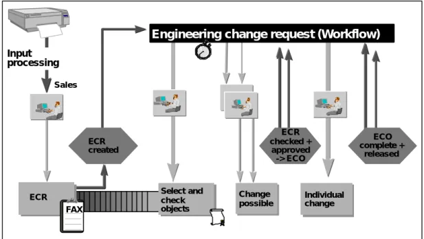
4.3.1 Common Approach to the ECM ... 52
4.3.2 Engineering Change Management using ready to use system (SAP) ... 53
4.4 ENGINEERING CHANGE MANAGEMENT AND REFERENCE PROCESS...55
4.5 ENGINEERING CHANGE MANAGEMENT AND FEATURE BASED MODELING...55
4.5.1 Importance of standardization ... 55
4.5.2 Interface ... 55
5.1 WORKFLOW, WORKFLOW MANAGEMENT AND WORKFLOW MANAGEMENT SYSTEM...57
5.2 WORKFLOW DESIGN...58
5.3 WORKFLOW DEFINITION...59
5.3.1 Process Definition Tools ... 59
5.3.2 Workflow Definition Interchange ... 60
5.3.3 A Basic Meta-Model ... 60
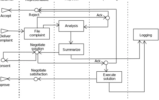
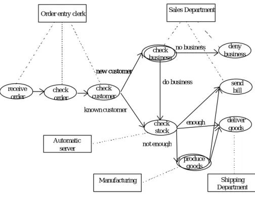
5.3.4 Examples of process definition ... 61
5.4 WORKFLOW OPERATION...64
5.5 WORKFLOW MANAGEMENT FOR CONFLOW PURPOSES...65
REFERENCES ... 66
Summary
The purpose of this document is to describe the main types of management and the Mechanisms Required to Enable Concurrent Engineering Workflow. Apparently all these main types of management have an influence on the Concurrent Engineering Workflow process and have to be examined.
Concurrent Engineering Workflow needs a comprehensive analysis of the following types of management:
• Structure Management;
• Configuration Management;
• Change Management;
• Workflow Management.
In the next sections the different types of management with their definitions, objectives, some application in different systems and possibilities for feature based management are mentioned.
In Structure Management part first product structure as bill of materials and feature-based models is
described. Then a mechanism extending feature descriptions generated by CAD system with additional non-shape properties is explained and the mechanisms for integration of bill of materials and feature-based models are presented to obtain the ConFlow aims.
Configuration Management depicts the mechanisms enabling product description as a whole and interdependencies between its components;
In Change Management the mechanisms enabling change request generation and change request data
distribution to the affected processes are characterised.
In Workflow Management the mechanisms enabling process (workflow) description, management and
execution are described.
For each type realisations in different systems are shown and examples are given. The suggested approach will be developed in details during the next tasks of the project.
1 Introduction
The purpose of this task is to present the main mechanisms supporting Concurrent Engineering Workflow. Many nowadays systems deal with one or more parts of this process.
PDM systems are sources of strength to fulfil concurrent engineering philosophy.
WFM systems provide tools for complete definition, management and execution of workflow processes. Enterprise Information systems attaining PDM and WFM functionality combine capabilities of these two types of systems for achieving maintenance of product structure and process representations in a common environment.
Above-mentioned functions are feasible in the cases of existing products. More powerful systems support tools for description variants and modifications of an existing product. Challenging situations in practice are these when it is necessary to carry out a non-existent modification. In some systems module Change Management performs this task. Input information for such module is Change Request – in the most cases a form that has to be fulfilled manually. It seems possible to extend change management functionality and to achieve generation of Change Request, using product structure information.
Each requirement to the product “quality” (functional characteristics, size, appearance etc.) could be transformed to the quantity characteristics of some of its component. In other words, a given modification could be presented as a requirement to use concrete materials of concrete sizes as product components. This is not simple transformation and can be supported by appropriate expert system.
In this way the change request information would result to the product structure and to the process definition. The following mechanisms are necessary:
• Product Structure Management enabling integration of different types of product structure
presentations (CAx, PDM, MRP/ERP);
• Configuration Management enabling product description as a whole and interdependencies
between its components;
• Workflow Management enabling process (workflow) description, management and execution;
• Change Management enabling change request generation and change request data distribution
to the affected processes.
Applying these mechanisms the new quality request will be transformed to the new workflows as follows. The first step as it was mentioned above is obtaining quantity characteristics as a result of quality change request. Product structure management involves this request in product structure representation. Configuration management allows defining other affected product components. The result is complete change request. Change management administers new change request and produces workflow changes request. Workflow management manipulates the request and creates workflows leading to the desired product development.
2 Structure management
2.1 Definition
Structure and Configuration Management is the ability to manage the elements of a product or project as a structure and/or the relationships between those elements (the configuration) as the structures evolve with time or produce variants. /EDMS_PDM/
With complex products and projects it is common to develop variants or specials for particular customers or markets. For maximum cost efficiency, the core of any group of variants should be managed as a single structure, i.e. it should be possible to reflect a change to the core in all variants derived from that core. However, different variants may be in different stages of design and any given variant may have instances in production or in service (this is the life-cycle management element). The more sophisticated PDM systems provide the tools to manage all the complexity and to automate many of the processes. It is, however, important to remember that there is a significant cost in properly modelling those processes and coding them into the PDM system. It is then necessary to ensure that everyone involved in the process has access to the PDM system and follows the rules and conventions laid down.
Structure and configuration management is similar to but different from the function provided by an MRP (Manufacturing and Requirements Planning) system in that Structure and configuration management includes the ability to search back (or forwards) time on configurations that have been built in the past (or which are planned for the future). Moreover, EDMS and PDM systems do not compete with an MRP system’s ability to plan and control real time manufacturing operations. What they can do is to assist in the process, often poorly documented, of preparing a ‘live’ BOM (Bill of Materials) for manufacturing or building. Once this has been prepared, the MRP system can manage the production process and feedback any changes (if allowed) that may be made.
In the very early phases of new product design, engineers begin the design by sketching out a structure for the product which identifies the major components and systems that will combine to create the desired product. For each component, existing standard parts and previously designed custom parts must be evaluated for their ability to provide the necessary function. In those cases for which no existing alternative can be identified, the engineer must specify that new parts should be created, and the details of the structure begin to emerge. Product structure management provides the mechanism to capture and manage as-designed product structures with ease. It allows for the creation and re-use of unlimited numbers of parts and assemblies, to provide for many different variations of a basic structure or the creation of complex, one-of-a-kind structures.
Product structure management shows for the selected product the relationship between its component assemblies and between the parts that make up these assemblies. That means that you can open a complete Bill of Materials, including documents and parts, either for the entire product or selected assemblies. Product structure management provides part list and bill of material functions, part definitions, part relationship attributes and the ability to associate product defining art to part and structure. One distinct advantage is the ability to hold not just the physical relationships between parts in an assembly but also other kinds of structures; for instance, manufacturing, financial, maintenance or document relationships. So, it is possible for specialist team members to see the product structured from their point of view.
Product structure management is an important component of production planning. All the data stored in BOM’s is used in various production planning activities, for instance, the design department can base its work on bills of material, the material requirements planning explodes bills of material to calculate order quantities on a certain date to minimize costs, and work scheduling uses bills of material as a basis for operation planning and production control.
2.2 Describing the product structure using BOM
2.2.1 BOM definitionMaterials is a complete listing of all piece parts, assemblies and any other items which are required to build and ship a product to a customer. A bill of materials encompasses all parts lists required in a product plus any other required items for shipping the product such as product support manuals.
A bill of material is a formally structured list for an object (semi-finished or finished product) which lists all the component parts of the object with the name, reference number, quantity, and unit of measure of each component. A bill of material can only refer to a quantity greater than or equal to one of an object. It is a product data structure, which captures the end products, its assemblies, their quantities and relationships. The structure of a part’s list determines the accessibility of the part’s information by various departments in a company. It also helps to determine the level of burden put on the computational device in searching for product information. In many companies the BOM is structured for the convenience of individual departments. This, however, engenders problems in other departments.
There are usually two kinds of bills of materials needed for a product: engineering and manufacturing BOM. The engineering BOM normally lists items according to their relationships with parent product. But this may not be sufficient to show that manufacturing constraints or tolerances may force the arrangement on the product structure to be different in order to assure manufacturability. Thus, engineering and manufacturing will usually have different valid views for the same product.
2.2.2 BOM in SAP R/3
In SAP R/3 the whole product structure management is processed by BOM’s. In accordance to the need, these BOM’s can be created for all SAP objects, such as materials, equipment and documents.
Material master BOM is normally used to describe the product structure. Possible entries are materials and documents. However, for all entered items the material master and the document info record must exist. Materials are not only raw materials, but also semi-finished or finished assemblies or products. /Rot_Goltz97/
Equipment master BOM is used to describe the equipment structure. Document info record BOM is known as document structure and is used to describe a complex document structure.
Material master BOM of given product is normally represented by:
• Single Bill of Material - it contains information about the material number, the plant code and the BOM
usage. The material has to be created in advance. The plant code is only necessary if the BOM shall be valid for a special plant. The BOM usage shows the department where this BOM is used -production, engineering design, costing, etc. Copying existing BOM’s can also create new BOM’s. On the next screen all desired components, called items, with quantity and unit of measure are entered in a table. It is feasible to maintain for every item a special screen where additional data is determined on another screen the BOM header can be maintained where the name of the BOM and the BOM group can be determined. The change of a BOM can be executed in reference to a change number.
• Configurable BOM - it is used to represent a product with many variants in one BOM. In this BOM are
entered beside the materials used in all variant also all selectable components. To create a BOM of one special variant selection parameters are used. These parameters, known as object dependencies, have to be defined and maintained. A configurable BOM contains information about all variants of this product. By displaying a BOM for a special variant the system determine automatically the right components in accordance to the configuration profile. Normally, all possible components, non-variable and variant parts, have to be entered. To every variant part a special selection criteria is maintained. Entering all variant parts with their selection criteria can be very expandable. To reduce the effort of maintenance it is feasible to use the classification system of R/3 and enter class items in the BOM. These classes contain the materials with their characteristics and possible characteristic values. By configuring, special values for these characteristics can be assigned and determine therefore that variant. Furthermore there is the possibility to define dependencies between the objects.
Two types of BOM’s are available to represent similar production alternatives in SAP R/3. These are:
• Variant BOM - it groups together several BOM’s to describe different objects, for example products,
which have a high proportion of identical parts. A variant BOM describes the specific product variant for each product, with all its components and assemblies. A variant can be created only from an existing BOM. This, for example, will be done when by replacing of one component a new product is created.
• Multiple BOM - it gathers together several BOM’s to describe one object (a product, for example) made up of different combinations of materials for different processing methods.
BOM group is used to group together material BOM’s which describe one product or several similar products. A BOM group can contain all variants of a variant BOM or all alternatives of a multiple BOM.
BOM usage
Every department has its peculiar view of the data and may not need all information available. For example, the calculating department needs only the components of a product that are cost relevant. To consider this fact, there are two opportunities available. First, it is feasible to create BOMs for every area in the company in accordance to the special needs. These BOM’s have no connections among themselves and are maintained separately then. For every view it can be defined that also items which are relevant for other areas can be entered. Otherwise, one big BOM, which includes all required information, has to be created. In this BOM are entered all components of a product. To signify their relevance several indicators are set. By explosion of the BOM you can define the demanded/peculiar view of the BOM. All other materials/components are then faded out.
Reporting functions
The system supports some report functions to evaluate the information of a bill of material, including:
• Where used lists - gives an easy overview of the products where a given material is contained. This
happens by displaying of all BOM’s, which contain this component. The function is also available for documents and classes. However, before the list can be generated some selection criteria have to be entered. This determines how the list will be displayed. A search can be executed directly over the material or indirectly over the class. Furthermore entering the plant, item category and BOM usage can restrict the range of search. The system determines then only the BOM’s in that the item has these attributes.
• BOM explosions - they are used to display what materials belong to the product. There are two
different options to uncompress a BOM, structure reporting function, such as ‘multi-level BOM’, and quantity based function, such as ‘summarised BOM’. After selecting the desired exploding function the user has the possibility to choose the demanded view of the information, for example, the department of production planning want to see only the components which are relevant for production orders. Also for better representation the graphic editor of R/3 can be used to display a multi-level BOM. From both representations the user can go to the material master record or to detailed information about the items. It is also potential to go to the ‘where-used list’.
• BOM comparisons - another possibility to evaluate information is the comparison of two BOM’s.
There are two ways to execute it, the summarised and the differentiated comparison. With the first possibility the quantity of each double found component are added. Otherwise, each occurring component is displayed separately. In addition it is feasible to determine the detail, which have to be compared. The system checks the BOM in accordance to these details. A ‘flash’ means no conformity, an ‘=‘ means equal in accordance to the chosen detail and an ‘≠‘ means similar but not equal.
2.2.3 BOM in Pro/Engineer and Pro/INTRALINK 2.2.3.1 Pro/INTRALINK structure management Pro/INTRALINK components
Pro/INTRALINK is an integrated environment that consists of five major components /Pro_INTR/:
• Pro/COMMONSPACE
• Pro/WORKSPACE
• Pro/LOCATE
Pro/COMMONSPACE
The Pro/COMMONSPACE application is used to store, find, view and modify information within the Commonspace database. Typically, modifications made in the Pro/COMMONSPACE application pertain to a single task or all versions of an individual object. When multiple tasks or changes are planned, users typically use the Pro/COMMONSPACE application to identify the desired objects and then check the object out to their local Workspace database for modification.
The Commonspace Browser
It is used to view the contents of Commonspace database and information and attributes relating to the various objects stored there. The Commonspace browser consists of menus and buttons, a folder tree and the object table. The object table displays information about the objects in a selected folder. Depending on the active table display, this information can include system attributes, user-defined attributes, access information and status notifications. The object table displays the latest version of each object contained in a folder. If an object version for each branch is displayed the Pro/COMMONSPACE application provides a set of standard reports to assist you in identifying objects as well as related components. Available reports include:
• Object Info – provides system attributes, user-defined attributes, and, if available, a simplified image of the object.
• Revision History – provides the change history of the object.
• Bill of Materials (BOM) – provides the hierarchy of objects required to assemble the selected assembly. This report enables you to display the product structure of a design. By default, the BOM report displays all of the objects that make up an assembly. – This is called a detailed display.
• Relationships – provides a list of all objects that are required to fully define and support an object. • Baselines – provides a list of all baselines in which a selected object exists. From this report you can
display the Set report, which is a list of all objects in these baselines.
• Where Used – provides a list of all objects that depend upon or reference the selected object.
• Authorisation – provides a list of user authorisations for the selected object, depending on your level of authorisation you may not be authorised to check out or modify certain objects.
The identification of objects and how they are related is an essential aspect of determining appropriate design changes and reuse. As your work with objects in the Workspace browser, you may need to extract various types of information beyond that which appears in the browser’s object table.
Pro/WORKSPACE
The Pro/WORKSPACE application is used to view and modify objects in the user’s local Workspace database. Users will typically copy information from the Commonspace database to their Workspace database to make modifications. Once the user has completed all tasks, the modified objects can be checked into the Commonspace database as a single action.
Each user has one local Workspace database, which acts as the repository of objects, checked out from the Commonspace. The Workspace database is divided into one or more workspaces. A workspace is a local project area, it provides a convenient environment for organising and working on objects.
The Workspace Browser
The Pro/WORKSPACE application is used to view and modify objects in the local workspace. The Workspace Browser enables the user to see the contents of one workspace and to view different attributes and information about the objects contained in the workspace. The Workspace Browser consists of menus and buttons, pull-down lists, displays, frames and the object tables.
The Pro/WORKSPACE application provides a set of standard reports to assist you in identifying objects and related components. Available reports include:
• Object Info – provides system attributes, user-defined attributes and a bitmap image, if it exists, of the object.
• Bill of Materials (BOM) – Provides the hierarchy of objects required to assemble the selected assembly and enables you to the product structure of a design. By default, the BOM report displays all of the objects that make up an assembly.
• Relationships – provides a list of all objects that are required to fully define and support an object. • Where Used – when modifying or reusing an object, it is critical to understand how a change affects
related components. This report provides a list of all objects that depend upon or reference the selected object.
The product structure can be viewed by the Commonspace browser. It is shown as a folder tree and the object table. Folders are used to logically organise the objects in the Commonspace database. Every folder in the tree represents a part of the product. In the folder tree, a + mode indicates a folder can be expanded to show sub-folders. A – node indicates a folder that has been expanded to show sub-folders. A folder without + or – contains no sub-folders.
The objects in the folder appear when click once on the folder to highlight it. In the object table can be viewed, depending on the active table display, system attributes, user-defined attributes, access information and status notification. The object table displays the latest version of each object contained in a folder. These objects can be parts or assemblies of the product.
Within the Pro/COMMONSPACE application, there are several ways you can add objects. You can create a new object, copy an existing object or create a new branch of an object. New objects can be based on object templates that you have created during the installation of Pro/INTRALINK in the directory named templates. By default, the templates directory contains two files: template.prt and template.asm. These are actual part and assembly objects that may not have any entities or geometry. The files however contain sufficient information to define their type.
A new object is created by selecting NEW from the OBJECT menu in the COMMONSPACE browser. The CREATE NEW OBJECT dialog box appears and there you have to enter the object name and select the type from the Object type list. Then you have to select the Commonspace folder for the new object from the list of folders.
Also, instead of creating a new object, you can reuse an existing object as the starting point for another design. Multiple objects can be copied together.
By default, all new objects are created with the Main branch. All new iterations of the objects remain on this branch, unless a new branch is created. A new branch creates a split in the version tree of an object so that multiple designs of an object can be worked on simultaneously without conflict. Branching enables you to develop multiple design alternatives concurrently and then optionally merge or delete after determining the best alternative.
In the Pro/WORKSPACE application you can also view, add and modify the objects in your own workspace. The objects from the current workspace are presented in an object table in the center area of the Workspace browser. Depending on the active table display, the object table can include system attributes, user-defined attributes, access information and status notifications or warnings. New objects in Pro/WORKPSACE can be created by selecting the NEW option from the OBJECTS menu in the Workspace browser. Then you have to enter the object name, select the type from the Object Type list and set the location of the object when it is checked into the Commonspace. You can also import objects into your Workspace database or copy objects from the existing object to create a new design in the same workspace. Also here the object attributes and relationships between objects can be created. The relationship structure is represented as a folder tree of existing parts, assemblies or layers. In the Configuration dialog box when select Dependency Option you can determine the required dependencies between objects.
Object types and object attributes are defined by Pro/ADMIN application. Object type definitions enable Pro/INTRALINK to identify, manage, and launch all types of files created by Pro/ENGINEER and non-native files created by other applications. Each object type has a unique file convention that Pro/INTRALINK uses to automatically associate the object type with a file format. Some of the object types are: Ansys Output, Assembly program, Pro/ENGINEER Assembly, BOM output, Bitmap file, CDRS
2.2.3.2 Structure management in Pro/Engineer
In Pro/Engineer structure management is represented mostly by the CAD model and there is also additional product structure information accessible via model information and BOMs. /Pro_ENG/
Model Information includes: Feature Information
You can find information about features by choosing Feat Info from the Info menu. After that you must specify a feature either by picking it with the mouse or using the Set by Menu option. Feat Info can be chosen in both part and Assembly modes.
Feature List
When you choose Feature List, the Information Window appears with a table listing the features in order and giving information, such as Number, ID, Name, Type, Suppression order and Regeneration Status (Regenerated, Unregenerated, Failed etc.)
Part Information
In Part Mode, the Info window appears immediately.
In Assembly Mode, choose Part from the Model info menu and specify a part, either by picking it with the mouse (Pick) or entering the name of the part (Name). Both regular and suppressed features are listed. In addition, all co-ordinate systems, cross sections, and reference dimensions are listed.
Assembly Information
You can access assembly information by choosing Model Info, then Assembly from the Info menu and then either picking on an assembly or specifying the name of the assembly, or choosing the Top Level to get information about the current assembly. An information window appears displaying the assembly information. The names of the components of the assembly display in a hierarchical structure to show how it was assembled.
Parent/Child Information
The Parent/Child option in the Info menu is used the relations between features. If you select either option Parents or option Children, you can then choose either to create an information file or to highlight the appropriate geometry on the screen. If you choose the file option, the information is written to a file and displays in the Information window.
The Parent/Child menu options are:
Parents – shows all the parents for the selected feature. The parent features highlight in the Reference Color.
Children – shows all the children of the selected feature. The child features highlight in the Reference Color.
References – shows, one at a time, all the references used to construct the feature. These can be axes, datums, surfaces, edges or other features. They are shown in the Internal Reference Color.
Child Ref – shows the references for each and highlights in the Surface mesh color and the surfaces, edges or points which they reference highlight in the Internal Quilt Edge color.
Bill of Materials in Pro/Engineer
A bill of materials (BOM) is a listing of all parts and part parameters in the current assembly. You can customize the output format to produce a particular form of presentation and content. BOMs can be created for assemblies in Assembly mode or from assembly drawings in Drawing mode. The optional module Pro/REPORT provides functionality to create BOM reports: graphical BOM with complex formatting and indexing.
The default output format for the BOM is divided into two sections:
• Breakdown – lists the name, type and number of instances of each member and sub-member.
• Summary – lists the total quantity of each part included in the assembly. It amounts to a ”shopping
A user-defined BOM output format specifies the format of the breakdown section and the summary section separately. You can include one or both sections, but you must specify the column titles, row content and display format for each included section.
2.2.4 Structure definition of Manometric Thermoregulator using SAP R/3
The first step in creating BOM for the product is to clarify the product structure./Rot_Goltz97/ Below on Figure 1 is given the new structure scheme of the Manometric Thermoregulator which is obtained on the basis of the latest product observation.
Structure Scheme of Manometric Thermoregulator
5 7 8 9 10 12 11 14 13 16 17 19 20 21 22 23 24 1 2 3 4 Legend: - Assembly
- Self manufactured part
- Standard part (ß - Purchased part Case |1 Adjusting screw |1 Special nut |1 Bracket |1 Constraint washer |1 Plate spring |1 Aluminium rivet Ø2.5x6 (ß |4 Aluminium rivet Ø2x5 (ß |2 Compaund case |1 Membrane |1 |1 |1 |1 End piece Sensitive device |1
Special plate spring |1 Lever |1 Button (ß |1 Aluminium rivet Ø2x5 (ß |2 Compaund lever |1 Lever with sensitive device
|1 Contact plate |1 Isolating block (ß |1 Bush |1 Screw M3x5 |1 Terminal |1 |2 Screw M3x8 (ß |1 Screw M3x12 (ß |1 Contact block |1 Pin |1 Isolating lamina |1 |1 Cantilever |1 Screw M3x14 (ß |2 Screw M3x12 (ß |1 Thermoregulator Capillary pipe |1 Body |1 Sensor 15 Holder
Stationary contact plate |1 25 Clamp 14 26 27 28 30 6 29 6 18 Figure 1
From the scheme, shown on Figure 2, we can derive the following structure scheme needed for BOM determination:
The blocks designated with ‘Subassembly 1’ to ‘Subassembly 5’ represent another assemblies on their
turn. Some standard parts are also included in these subassemblies, such as: aluminium rivet ∅ 2.5x6,
aluminium rivet ∅ 2x5, screw M3x8, screw M3x12, screw M3x14. Some of the components are
purchased parts and can be presented in SAP R/3 as non-stock items. These are: aluminium rivet ∅
master records for the different items have to be created first. Using the following sequence of SAP R/3 menu options can create material master record:
Logistics → Production → Master data → Materials Material → Create (general) → Immediately
Figure 2
The necessary data for material creation are material number, material type and industry sector. If material number is not entered, the system will assign an internal number to the material. Material type and industry sectors are obligatory. Let us consider one assembly of Manometric Thermoregulator -Compound case, for example. On the Figure 3 is given the structure scheme of -Compound Case assembly:
When we create the material master record for the Compound case it is appropriate to choose “M” (Mechanical Engineering) for the industry sector and “FERT” (Finished Product) for the material type. After confirming this data the “Select view(s)” dialog box appears. Here different views of the material can be chosen: Basic data, MRP1, MRP2, Costing, etc. By pressing “organizational levels” button the material can be associated with a certain plant.
Figure 4
After choosing “Basic Data” view from the “Select view(s)”, a new dialog box appears. Here the following fields have to be filled with data: Base units of measure, Weight, Height, Size/Dimensions, Material description, Basic material. On the Figure 4 and Figure 5 are presented the material master records for two components of the Compound case assembly. The material Case is self-manufactured part, made of steel. The material Aluminium rivet ∅2.5x6 is non-stock item (purchased part).
Next step is to create Bill of Material for the Compound case assembly. BOM can be created by the following sequence of menu options:
Logistics → Production → Master data → Bills of materials Bills of materials → Material BOM → Create
On the Figure 6 the initial screen for BOM generation is shown. In this dialog box have to be entered the material number for the assembly in the field “Material” and the area, where this product will be used, in the field “BOM usage”. In this case it is appropriate to choose “2 - Engineering/design” for the assembly BOM usage. The field designated with “Plant” is not obligatory, it is used only in case that the BOM is valid for a certain plant.
Figure 6
After entering this data a new dialog box appears, as shown on the Figure 7. Here all BOM items, representing the components of the Compound case assembly, have to be filled in. The necessary information for the items includes the material number and description, the number of items, the unit of measure, the item category, dates of validation. All BOM items use PC (piece) as unit of measure. There are two Item categories in our case: L (Stock item) for self-manufactured parts and N (non-stock item) for purchased parts.
Figure 7
It is recommendable also to create document info records for all BOM items. Document info record contains all the information connected to the document, such as: processing status, storage location, and administrative data. It is necessary to define an identification key for the document, which consists of four parts: document number, document type, document part and document version. The documents usually represent the external files connected to the selected component of the assembly. These external information files can be Pro/Engineer drawings, text files, AutoCAD drawings etc.
2.3 Describing the product structure using CAD model
The geometric modelling includes the digital representation methods of objects geometrical shapes together with other non-geometrical information presented in form ready for processing by an interactive system for machine graphics.
Different techniques for geometric model creating exist , such as: 2D, 2 1/2D, Wire Frame representation (WF-rep), Boundary Representation (B-rep), Constructive Solid Geometry (CSG) etc.
In this research we focus our interest on the last mentioned model. In Constructive Solid Geometry (or Solid) the concept of matter is introduced in the process of object definition. CSG is represented as a tree structure, whose elements are simple volume primitives, such as cubes, cylinders etc., and nodes are boolean operations Union, Subtraction and Intersection. Each node is an intermediate object. The tree root is final volume object model.
CSG is used as a synonym of so called volume modelling. In the computer processing all transformations are represented by the volume model tree, i.e. the model is procedural but not only a set of geometrical information.
Solid Geometry is fundamental because the volume procedure model can be transformed into any other representation.
2.3.1 CAD model in AutoCAD
The AutoCAD Advanced Modelling Extension (AME) is solid modelling software./ACAD_AME/ The solid modeller in AME lets create solid.
Creating Primitives
AME has six commands that create simple solid shapes: box or cube, wedge, cone, cylinder, sphere and donut.
SOLBOX - creates 3D solid box or cube. SOLWEGE - creates 3D solid wedge.
SOLCONE - creates 3D solid cone with circular or elliptical base. SOLCYL - creates 3D solid circular or elliptical cylinder.
SOLSPHERE - creates 3D solid sphere.
SOLTORUS - creates 3D solid with a donut-like shape.
These primitives are the basic building blocks for creating more complex solid models. Composite Solids
When several solids are combined to form a single object, it is called a composite model. A composite model can consist of primitives, other composite models, or a combination of the two. AME has eight commands that create composite models: SOLUNION, SOLINT, SOLSUB, SOLEXT, SOLREV, SOLCHAM and SOLFILL.
SOLUNION creates a composite model by joining objects together. SOLINT finding the common volume of several objects. SOLSUB by subtracting objects from one another.
SOLEXT create a composite solid by extruding 2D objects. SOLREV create a composite solid by revolving 2D objects
SOLCHAM and SOLFILL create composites solids by creating a solid primitive in the shape of chamfer or fillet and adding it to or subtracting it from the selected solid.
SOLINTERF creates a solid that is the interference (intersection) of two or more solids.
Can separate composite model created with SOLUNION, SOLINTand SOLSUB by using the SOLSEP command.
Model information
SOLLIST command gives the possibility to view the CSG tree structure of composite model.
Object type = SUBTRACTION Handle = 3CC354 Component handles: 3CBFF9 and 3CC014 Area not computed Material = MILD_STEEL
Representation = WIREFRAME Render type = CSG
.... Object type = SUBTRACTION Handle = 3CBFF9 .... Component handles: 3CBE2A and 3CBE53 .... Area not computed Material = MILD_STEEL
.... Representation = WIREFRAME Render type = CSG .... Node level = 1
.... Object type = SUBTRACTION Handle = 3CBE2A .... Component handles: 3CBCB0 and 3CBD38 .... Area not computed Material = MILD_STEEL
.... Representation = WIREFRAME Render type = CSG .... Node level = 2
.... Object type = SUBTRACTION Handle = 3CBCB0 .... Component handles: 3CBC0D and 3CBC75 .... Area not computed Material = MILD_STEEL
.... Representation = WIREFRAME Render type = CSG .... Node level = 3
.... Object type = EXTRUSION (20, 7.500000, 0.000000) Handle = 3CBC0D .... Area not computed Material = MILD_STEEL
.... Representation = WIREFRAME Render type = CSG .... Node level = 4
.... Object type = EXTRUSION (4, 6.000000, 0.000000) Handle = 3CBC75 .... Area not computed Material = MILD_STEEL
.... Representation = WIREFRAME Render type = CSG .... Node level = 4
.... Component handles: 3CBD15 and 3CBD33 .... Area not computed Material = MILD_STEEL
.... Representation = WIREFRAME Render type = NONE .... Node level = 3
.... Object type = EXTRUSION (8, 6.000000, 0.000000) Handle = 3CBD15 .... Area not computed Material = MILD_STEEL
.... Representation = WIREFRAME Render type = CSG .... Node level = 4
.... Object type = EXTRUSION (8, 6.000000, 0.000000) Handle = 3CBD33 .... Area not computed Material = MILD_STEEL
.... Representation = WIREFRAME Render type = CSG .... Node level = 4
.... Object type = UNION Handle = 3CBE53 .... Component handles: 3CBE4F and 3CBE43 .... Area not computed Material = MILD_STEEL
.... Representation = WIREFRAME Render type = NONE .... Node level = 2
.... Object type = CYLINDER (0.300000, 0.300000, 6.000000) Handle = 3CBE4F .... Area not computed Material = MILD_STEEL
.... Representation = WIREFRAME Render type = CSG .... Node level = 3
.... Object type = CYLINDER (0.300000, 0.300000, 6.000000) Handle = 3CBE43 .... Area not computed Material = MILD_STEEL
.... Representation = WIREFRAME Render type = CSG .... Node level = 3
.... Object type = UNION Handle = 3CC014 .... Component handles: 3CC012 and 3CC013 .... Area not computed Material = MILD_STEEL
.... Representation = WIREFRAME Render type = NONE .... Node level = 1
.... Object type = FILLET (0.300000) Handle = 3CC012 .... Area not computed Material = MILD_STEEL
.... Object type = FILLET (0.300000) Handle = 3CC013 .... Area not computed Material = MILD_STEEL
.... Representation = WIREFRAME Render type = NONE .... Node level = 2
2.3.2 CAD model in Pro/Engineer
Pro/ENGINEER another approach for model creating is applied - Feature Based Modelling./Pro_ENG/ The idea is to separate one object properties group from a given application area and to give the possibility to the designer to create the model by specifying the typical features. The Form Features idea corresponds to the manufacturing engineer’s point of view, which is formulated from often work with metal cutting./St_Dimov95/ So, the designer thinks in terms, such as hole, fillet, chamfer etc. In this case features can be determined as properties which define the object itself in the context of certain stage, i.e. the objects are set of features and their relations.
The main advantage of this approach is that the designer works mostly with general concepts and properties than with concrete geometrical terms.
In Pro/ENGINEER the principles of parametric projection and Feature-Based Solid Modelling are combined. Unlike AutoCAD here the geometry is a secondary result from the different component interdependence - features. The model is completely integrated and accessible for processing by all the modules of the system. There is no matter if a change in the 3D model has to be done or in the dimensions in any 2D projection etc. The changes will be applied in all the drawings and representations in every module of Pro/ENGINEER. This way the drawings always show the current state of the model and vice-versa.
Solid model construction techniques
Features are simple basic shapes and are considered solid modelling entities, which can be combined by a mathematical set of Boolean operations to create the solid. Features themselves are considered valid “off-the-shelf” solids. In addition, Pro/ENGINEER supports sweeping operations that permit users to utilise wire-frame entities (sketched sections) to create faces that are swept later to create solids. Also, in Pro/ENGINEER, Pure Primitive Instancing (PPI) technique is supported to duplicate features that are topologically identical but vary in size from the nominal features.
Feature types that are used in Pro/ENGINEER as building blocks are:
• Protrusions. A protrusion is a design feature that adds material. It is always the first solid feature
created. Four options exist for creating protrusion features:
Extrude. This option forms the feature by projecting a section straight away from the sketching plane. It is the most basic and frequently used form option.
Revolve. The revolve option creates a feature by revolving the sketched section around a centerline from the sketching plane into the part. When sketching the feature, the first centerline sketched is the axis of revolution. The section must lie completely on one side of this centerline and must be closed.
Sweep. A sweep is created by sketching or selecting a trajectory and then sketching a section to follow alone it. With Pro/Feature, sweeps can be created along a three-dimensional path by creating a three-dimensional (3D) spline for the sweep trajectory.
Blend. A blended feature consists of a series of at least two planar sections, which are joined together at their edges with transitional surfaces to form a continuous feature. Blends with parallel sections can be created in Basic Pro/ENGINEER, but the optional modules Pro/Feature and Pro/Surface provide the functionality required for creating blends from nonparallel sections.
Slots and cuts. Both slots and cuts remove material from a part
Slot features are used when there is a need to remove material within a closed section. Cut features are employed when you want to specify to which side to remove material.
• Holes. This type of feature is used to create many types of holes, e.g. through holes, counterbored holes, and blind holes. They are all based on two basic types of hole geometry, “straight” and “sketched”.
A “straight” hole is an extruded slot with a circular section. It passes from the placement surface to the specified end surface.
A “sketched” hole is a revolved feature and is defined by a sketched section. Counterbored and countersunk holes, for example, are created as sketched holes.
• Shafts. Shafts are analogous to blind holes. Both are created by sketching sections of revolution and
then placing them on the model. However, shafts add material instead of removing it.
• Rounds. The round option creates a fillet or a round on an edge, that is, a smooth transition with
either a conic or circular profile between two adjacent surfaces.
• Chamfers. Two types of chamfers exist: edge and corner chamfers. An edge chamfer removes a flat
section of material from a selected edge to create a beveled surface between the two original surfaces common to that edge. A corner chamfer removes material from the corner of a part.
• Necks. A neck is a special type of revolved slot, which creates a groove around a revolved part or
feature.
• Flanges. A flange is analogous to a neck except that it adds material to the revolved solid.
• Ribs. A rib is a special type of protrusion designed to create a thin or web which is attached to a part.
It is always sketched from a side view and grows symmetrically about the sketching plane.
• Shells. The shell option removes a surface or surfaces from the solid and then hollows out the inside
of the solid, leaving a shell of a specified wall thickness. When the shell is made, all features that were added to the solid before choosing shell will be hollowed out.
• Pipe. The pipe feature is a 3D centerline representing the centerline of a pipe. Given the diameter of
a pipe and, for a hollow pipe, the wall thickness, it connects selected datums points either with a combination of straight lines and arcs of specified bend radius, or with a spline.
• Cosmetic features. The cosmetic features are three types: sketched cosmetic, tread and groove.
Sketch cosmetic features are those that are “drawn” on the surface of a part. They include such things as company logos or serial numbers, which are stamped on an object, or are used to define the boundaries of a region for FEM partial loads.
A thread is a cosmetic feature representing the diameter of a thread.
A groove is a projected cosmetic feature. It is created by making a sketch and projecting it onto a surface.
Feature-based modelling
Features generally fall into one of the following categories:
Base Features - The base feature may be either a sketched feature or datum plane(s) referencing the default coordinate system (MCS). The base feature is important because all future model geometry
will reference this feature directly or indirectly; it becomes the root feature. Changes to the base
feature will affect the geometry of the entire model.
Sketched Features - In general, sketched features are created by extruding, revolving, blending, or sweeping a sketched cross section. Material may be added or removed by protruding or cutting the feature from the existing model.
Referenced Features - Referenced features reference existing geometry and employ an inherent form; they do not need to be sketched. Some examples of referenced features are rounds, drilled holes, and shells.
The various types of features are used as building blocks in the progressive creation of solid parts. Figure 8 demonstrates this process.
(a) Based Feature (Figure 8 a). A revolved protrusion from a sketched cross-section.
(b) Datum Features (Figure 8 b). A datum plane created at zero offset normal to z-axis of the default coordinate system.
(c) Sketched Feature (Figure 8 c). Extruded protrusion sketched on datum plane with center aligned to the top of the base feature.
(d) Referenced Features (Figure 8 d). A hole drilled coaxially through the top protrusion; rounds created along the sharp edges.
a b
c d
Figure 8
Because feature-based modelling in Pro/ENGINEER is cumulative process, certain features must, by necessity, precede others. Those that follow must rely on previously defined features for dimensional and geometric references. This relationships between features and those that reference them are termed parent-child relationships. Because children reference parents, features can exist without children, but children cannot exist without their parents.
The parent-child relationship is one of the most powerful aspects of Pro/ENGINEER; when a parent feature is modified, its children are automatically revised to reflect the changes in the parent feature’s geometry. It is therefore essential to reference feature dimensions so that design modifications are correctly propagated through the model. Just as parts are created from related features, so assemblies are created from related parts.
Capturing design intent
A valuable aspect of any design tool is its ability to not only render the design, but to capture its intent.
The concept of capturing design intent is based on incorporating engineering knowledge into a model by establishing and preserving certain geometrical relationships. The wall thickness of a pressure vessel, for example, should be proportional to its surface area, and should remain so even its size changes. Pro/ENGINEER captures these relationships in several ways:
Implicit Relationships - Implicit relationships occur when new model geometry is sketched and dimensioned relative to existing features and parts. An implicit relationship is established, when the section sketch of a tire uses rim edges for reference.
Patterns - Design feature often follow a geometrically predictable pattern. Features and parts are patterned in Pro/ENGINEER by referencing either construction dimensions or existing patterns.
Explicit Relations - While implicit relationships are implied by the feature creation method, an explicit
relation is mathematically entered by the user. This equation is used to relate part and feature dimensions in the desired manner.
Family Tables - Family tables are used to create part families from generic models by tabulating
dimensions or the presence of certain features or parts. A family table might be used, for example to catalog a series of wheel rims with varying width and diameter.
Model Information Feature Information
Pro/ENGINEER can find information about features. The Information Window appears with a table listing the features in order and giving information, such as Number, ID, Name, Type, Suppression order and Regeneration Status.
Assembly Information
An information window appears displaying the assembly information. The names of the components of the assembly display in a hierarchical structure to show how it was assembled.
Below is given an example of the structure of the same Manometric Thermoregulator component - Plate spring which was examined in 2.3.1.
VERSION 18.0 REVNUM 1748
LISTING FOR PART PLATE SPRING INPUT
END INPUT RELATIONS END RELATIONS
ADD FEATURE (initial number 1) INTERNAL FEATURE ID 1 TYPE = DATUM PLANE NAME = DTM1
END ADD
ADD FEATURE (initial number 2) INTERNAL FEATURE ID 3 TYPE = DATUM PLANE
ADD FEATURE (initial number 3) INTERNAL FEATURE ID 5 TYPE = DATUM PLANE NAME = DTM3
END ADD
ADD FEATURE (initial number 4) INTERNAL FEATURE ID 7 TYPE = COORDINATE SYSTEM NAME = CS0
END ADD
ADD FEATURE (initial number 5) INTERNAL FEATURE ID 9 PARENTS = 1(#1) 3(#2) 5(#3) FIRST WALL: Flat
NO. ELEMENT NAME INFO STATUS
--- --- ---
1 Section Sk. plane - Surface DTM3 of feat #3 (DATUM PLANE) Defined
2 Thickness Thickness = 0.5 Defined
SECTION NAME = S2D0004 FEATURE'S DIMENSIONS: d1 = 16 d2 = 33.05 d3 = 8 d4 = 0.5THICK END ADD
ADD FEATURE (initial number 6) INTERNAL FEATURE ID 60 PARENTS = 9(#5)
ROUND: General
NO. ELEMENT NAME INFO STATUS
--- --- ---
1 Round Type Simple Defined
2 Attributes Constant, Edge Chain Defined
3 References Defined
4 Radius Value = 2.0000 Defined
5 Round Extent Optional
6 Attach Type Make Solid - Feature has solid geometry Defined
FEATURE'S DIMENSIONS: d5 = 2R
END ADD
ADD FEATURE (initial number 7) INTERNAL FEATURE ID 94 PARENTS = 3(#2) 9(#5) TYPE = BEND SECTION NAME = S2D0005 FEATURE'S DIMENSIONS: d6 = 8 d9 = 15 d10 = 4R d11 = 1.09DEV.L END ADD
ADD FEATURE (initial number 8) INTERNAL FEATURE ID 320 PARENTS = 1(#1) 9(#5) 94(#7) CUT: Smt Cut
NO. ELEMENT NAME INFO STATUS
--- --- ---
1 Section Sk. plane - Surface of feat #7 (BEND) Defined
2 MaterialSide Inside section Defined
3 Depth Through All Defined
4 Driving Surf Green Side Defined
SECTION NAME = S2D0008 FEATURE'S DIMENSIONS: d22 = 7.5 Dia
d23 = 9.5 END ADD
ADD FEATURE (initial number 9) INTERNAL FEATURE ID 343 PARENTS = 9(#5) 60(#6) 94(#7) TYPE = WALL SECTION NAME = S2D0009 FEATURE'S DIMENSIONS: d26 = 1 d29 = 5 d30 = 2 END ADD
PARENTS = 343(#9) TYPE = WALL SECTION NAME = S2D0011 FEATURE'S DIMENSIONS: d31 = 90 d36 = 2 d37 = 1R d38 = 1.82DEV.L END ADD
ADD FEATURE (initial number 11) INTERNAL FEATURE ID 511 PARENTS = 422(#10) TYPE = WALL SECTION NAME = S2D0012 FEATURE'S DIMENSIONS: d39 = 90 d44 = 2 d45 = 1R d46 = 1.82DEV.L END ADD
ADD FEATURE (initial number 12) INTERNAL FEATURE ID 598 PARENTS = 511(#11)
ROUND: General
NO. ELEMENT NAME INFO STATUS
--- --- ---
1 Round Type Simple Defined
2 Attributes Constant, Edge Chain Defined
3 References Defined
4 Radius Value = 1.0000 Defined
5 Round Extent Optional
6 Attach Type Make Solid - Feature has solid geometry Defined
FEATURE'S DIMENSIONS: d47 = 1R
END ADD
ADD FEATURE (initial number 13) INTERNAL FEATURE ID 640
PARENTS = 9(#5) 60(#6) 94(#7) 343(#9) TYPE = WALL
SECTION NAME = S2D0015 FEATURE'S DIMENSIONS: d52 = 2
END ADD
ADD FEATURE (initial number 14) INTERNAL FEATURE ID 722 PARENTS = 640(#13) TYPE = WALL SECTION NAME = S2D0011 FEATURE'S DIMENSIONS: d55(d31) = 90 d60(d36) = 2 d61(d37) = 1R d62(d38) = 1.82DEV.L d72 = 1.82DEV.L
THIS FEATURE WAS COPIED ALONG WITH THE FOLLOWING FEATURES 726 727
END ADD
ADD FEATURE (initial number 15) INTERNAL FEATURE ID 726 PARENTS = 640(#13) 722(#14) TYPE = WALL SECTION NAME = S2D0012 FEATURE'S DIMENSIONS: d63(d39) = 90 d68(d44) = 2 d69(d45) = 1R d70(d46) = 1.82DEV.L d73 = 1.82DEV.L
THIS FEATURE WAS COPIED ALONG WITH THE FOLLOWING FEATURES 722 727
END ADD
ADD FEATURE (initial number 16) INTERNAL FEATURE ID 727
PARENTS = 640(#13) 722(#14) 726(#15) ROUND: General
2 Attributes Constant, Edge Chain Defined
3 References Defined
4 Radius Value = 1.0000 Defined
5 Round Extent Optional
6 Attach Type Make Solid - Feature has solid geometry Defined
FEATURE'S DIMENSIONS: d71(d47) = 1R
THIS FEATURE WAS COPIED ALONG WITH THE FOLLOWING FEATURES 722 726
END ADD
ADD FEATURE (initial number 17) INTERNAL FEATURE ID 1374 PARENTS = 1(#1) 9(#5) 94(#7) CUT: Smt Cut
NO. ELEMENT NAME INFO STATUS
--- --- ---
1 Section Sk. plane - Surface of feat #7 (BEND) Defined
2 MaterialSide Inside section Defined
3 Depth Through All Defined
4 Driving Surf White Side Defined
SECTION NAME = S2D0012 FEATURE'S DIMENSIONS: d74 = 4 d75 = 5 d76 = 4 d77 = 2.5 END ADD
ADD FEATURE (initial number 18) INTERNAL FEATURE ID 1411
PARENTS = 9(#5) 60(#6) 94(#7) 640(#13) 1(#1) CUT: Smt Cut
NO. ELEMENT NAME INFO STATUS
--- --- ---
1 Section Sk. plane - Surface of feat #7 (BEND) Defined
2 MaterialSide Defined
3 Depth Through All Defined
4 Driving Surf White Side Defined
SECTION NAME = S2D0031 OPEN SECTION
FEATURE'S DIMENSIONS: d80 = 15
d81 = 6.5 d82 = 8.5 END ADD
ADD FEATURE (initial number 19) INTERNAL FEATURE ID 1457 PARENTS = 3(#2) 9(#5) 1(#1) CUT: Smt Cut
NO. ELEMENT NAME INFO STATUS
--- --- ---
1 Section Sk. plane - Surface of feat #5 (FIRST WALL) Defined
2 MaterialSide Inside section Defined
3 Depth Through All Defined
4 Driving Surf White Side Defined
SECTION NAME = S2D0032 FEATURE'S DIMENSIONS: d83 = 2 d84 = 2 Dia d85 = 3 d86 = 9 END ADD MASSPROP END MASSPROP
2.4 Mechanism enabling the integration of Bill of Materials and CAD model
In nowadays CAD systems feature-based models are used to describe the product structure, as well as some directions of design, process planning and manufacturing, whilst in PDM systems the product structure is presented by bill of materials (BOM). These representations are sufficient for achieving the objectives and goals of such types of systems. Feature-based models are used not only in CAD systems but also in CAPP, CIM, CAM and PDM systems. Form features applied in CAD systems contain some information that can be useful for the purposes of other systems but it is not sufficient. This requests the development of different kind of features containing information that is more appropriate for using in CAPP, CIM, CAM and PDM systems. Usually, such information is presented in BOMs. Therefore, combining of these two representation methods could extent the functionality of a specific system.
A similar approach can be applied for obtaining the ConFlow project aims:
• extending feature descriptions generated by CAD system with additional non-shaped properties. This
way any particular feature is presented by the following properties:
- geometry including parameters, such as:
q complexity.
- topology including parameters, such as:
q parent feature,
q connection with other features.
- material, including ISO code
- surface integrity including parameters such as:
q roughness,
q state of surface structure,
q special layer parameter.
- others - for future expands.
An example concerning an assembly of Manometric Thermoregulator – Compound Case has been done using Pro/Engineer. First, CAD models of all the components, included in Compound Case, were created as drawings in Pro/Engineer. Then these components were assembled. Text files containing the product structure, represented by feature descriptions, were generated by Pro/Engineer. Additionally, other properties were included in the same text files where this information is available. These properties are the same as stated above.
• generating BOM for the same product from the system with PDM functionality.
The same example concerning Compound Case assembly of Manometric Thermoregulator has been realized using SAP R/3. First, material master records for every component were created. Also document info records, containing information about the external files connected to the selected component of the assembly, were made. These external information files can be Pro/Engineer drawings, text files etc. Then a material master BOM for Compound Case assembly, including all the components, was generated.
• connecting both product structure representations by the ISO code of material and the topological
parameter parent.
The idea of this mechanism enabling the integration of Bill of Materials and CAD model can be realized by development of additional software, connecting the two representations of Pro/Engineer and SAP R/3. The connection could be done via the names of the components in the assembly and the numbers assigned to all the components both in files, generated by Pro/Engineer and SAP R/3 BOM. Also this connection can be realized by ISO code of the material which is in the files generated by Pro/Engineer and in the material master records of every component. Connections between features determine other affected features that have to be changed in the same way. These modifications reflect on the processes related to the influenced features.
The stated here mechanism is bi-directional connection and enables the change management process – any requested change can be applied in both representations in CAD model and PDM Bill of Material.
3 Configuration Management
3.1 Configuration Management Definition
Configuration Management (CM) is a discipline for providing a systematic or organized approach to planning, identifying, controlling and accounting for the status of a product's configuration, from its inception throughout its life (that is, from birth to death). /Mon95/
We must have a plan of how you are going to manage the configuration or documentation of our product; we must have a numbering system such that we can use it to identify the content and types of documentation of our product; we must have some kind of a change control system to control changes to our product; and last but not least, we must be able to account for the status of a product's configuration due to changes which may be incorporated in the design for manufacturing in the future.
The term ‘configuration’ is defined as the technical description and arrangement of parts or assemblies or any combination of these which is capable of fulfilling the fit, form or functional requirements defined by the applicable product specification and drawings.
Hence, the term configuration is no more than the documentation, which describes a new product design. It is in fact the technical description of the arrangement of parts or assemblies, which go into making up this new product design. Now, when we look back at the term documentation and the term configuration we can easily see that they are in fact synonymous. From this point on, we will be using the term CM with the same meaning as engineering documentation control.
The other part of the term CM which may need to be defined is the term ‘management’. The important thing to remember as we work into a system called CM is that we are trying to manage the configuration or documentation of a product and we are going to do that by using the proper planning, identification, control and accounting for the status of a product(s) documentation or configuration.
CM is the ability to manage the relationships between product/process elements as a structure. These structures evolve with time or produce variants. With complex products and projects it is common to develop variants for particular customers or markets. For maximum costs efficiency, the core of any group of variants should be managed as a single structure, i.e. it should be possible to reflect the change to the core in all variant derived from that core. However, different variants may be in different stages of design and any given variant may have instances in production or in service.
A 'configuration' in a PDM system is effectively a superset of a bill of materials (BOM). It is the relationship between:
• Parts
• Assemblies
• Data files associated to the two mentioned above.
The new term, 'configuration' is used because the term 'BOM' has a strong manufacturing connotation and doesn't truly exist until a product is released to manufacturing.
A configuration can be set up at the initial design stage and used as a framework for development of the design. It can then be directly input into a BOM for the MRP system.
Configuration change throughout the product life cycles and managing these changes is known as CM. CM capabilities of PDM systems vary.
They can include the following:
CONFIGURATION TEMPLATES & MULTI-LEVEL EDITING. The template is a skeleton structure for the proposed product and represents a starting point from which the project team will develop the design. The template organises the product structure according to what is already known. Individual team members may then be given the responsibility to design specific parts and assemblies. The configuration is often shared between members of the team and it is important for the PDM system to provide a multilevel editing capability so that each team member can change the configuration at the level they own - subject