A Thesis
Submitted to the Faculty of
Drexel University by
George Dimanson Sworo in partial fulfillment of the requirements for the degree
of
Doctor of Philosophy in Feb 2015
Dedications
To my family: My beautiful wife Christine for her enduring love and patience; my sons Jahaziel and Hezekiah for giving me purpose in this life; my mother Grace without whose relentless love and support, I wouldn’t have gotten this far in life; To all my sisters for being there for me. To my Dad for coming back into my life. To Sally France without whose untold support and prayer I wouldn’t be where I am today. I am eternally grateful to you. To the Yugga family, whose resilience, and tenacity inspires me everyday. I will always be grateful for your constant love. Thank you all so much. God is so gracious to me!
Acknowledgments
I am deeply grateful to my Advisors Dr. Moshe Kam, and Dr. Kapil Dandekar for their guidance, insight and wisdom.
I would like to thank the Gwin family, especially my brother from another mother Christopher Gwin for being the big brother I never had. I am also very grateful to Frank Stiefel and his family for their true friendship; and to the countless friends whose acquaintances I have had the pleasure of meeting through my Haddonfield connection. Special thanks to the Hymerlings for their boundless generosity.
To Joe Sun, Megan Doherty, and the family at APO UPENN, Thanks for nurtur-ing and providnurtur-ing me with the best advice and environment to succeed at UPENN. To NSBE UPENN and Cora Ingrum, thank you for your academic mentorship.
To Peggy Hanefors for helping me find my feet at UPENN and for being a good friend. To my big brother in Christ and good friend, William Okech, thank you so much for always reminding me of who I am.
Special thanks to Longun Jimmy, Yengi Desmond, Maring Kennedy, and Allam Margret for their camaraderie and inspiration through a collective dream to serve our beloved nation of South Sudan and Africa at large. Lets keep on dreaming! Not forgetting Helen Kulabako and Windle Trust International for giving us a chance when no one did.
Many thanks to my lab mates at Data Fusion and Drexel Wireless Systems Labs. Time and space would not permit me to thank the countless people that I have been lucky enough to call friends during these formative years of my life. From the refugee camps to the United World Colleges to the University of Pennsylvania and Drexel University, you know who you are, I sincerely thank you from the bottom of my heart for being a part of this exciting journey of my life. Lets keep changing the world for the better.
Table of Contents
LIST OF TABLES . . . viii
LIST OF FIGURES . . . ix
ABSTRACT . . . xiii
1. INTRODUCTION . . . 1
1.1 Motivation and Problem Statement . . . 2
1.1.1 Brief Overview . . . 3
1.2 Problem . . . 5
1.3 Contributions . . . 8
1.4 Organization . . . 10
2. ADAPTIVE MULTI-ANTENNA COMMUNICATIONS SYSTEMS . . . 12
2.1 Adaptive Antenna Array Systems . . . 13
2.1.1 Reconfigurable Antenna Systems (RAS) . . . 13
3. MIMO COMMUNICATION ARCHITECTURES AND TECHNIQUES . . . 18
3.1 MIMO Transmission Architectures . . . 18
3.1.1 D-BLAST Transmission . . . 19
3.1.2 Vertical BLAST (V-BLAST) Transmission . . . 21
3.2 MIMO Signal Processing Techniques . . . 28
3.2.1 Spatial Multiplexing (SM) . . . 28
3.2.2 Space or Spatial Diversity (SD) . . . 30
3.2.3 Beamforming . . . 30
3.2.4 Hybrid MIMO and Beamforming . . . 31
4. SYSTEM MODEL: MIMO-OFDM FOR WIRELESS TRANSMISSION . . . 33
4.1 Orthogonal Frequency Division Multiplexing (OFDM) . . . 33
4.1.1 OFDM Transceiver . . . 35
4.2 MIMO-OFDM System. . . 39
5. RECONFIGURABLE ANTENNAS FOR WIMAX/LTE . . . 42
5.1 Introduction . . . 42
5.2 Reconfigurable Printed Dipole Array (RPDA) for WiMAX Applications 43 5.2.1 Antenna Design and Prototyping. . . 44
5.2.2 Antenna Parameters and Radiation Patterns . . . 47
5.2.3 Performance Testing: Experimental Setup and Results. . . 52
5.2.4 Summary and Conclusion . . . 54
5.3 Reconfigurable Alford for WiMAX/LTE . . . 56
5.4 Motivation. . . 56
5.4.1 Reconfigurable Alford Design . . . 56
5.4.2 Antenna Characterization . . . 57
5.5 Summary . . . 59
6. Spatially Adaptive Algorithm for Pattern RAS . . . 63
6.1 Introduction . . . 63
6.1.1 Related Work . . . 65
6.3 Spatially Adaptive Modulation and Coding (SAMC) Algorithm . . . 69
6.3.1 AMC Selection Algorithms . . . 72
6.3.2 Computational Complexity of SAMC . . . 76
6.4 Experimental Setup and Implementation . . . 80
6.4.1 Software Defined Radio (SDR) Testbed. . . 80
6.4.2 Reconfigurable Printed Dipole Array (RPDA) Antennas . . . 80
6.4.3 Measurement Setup . . . 83
6.5 Performance Results and Analysis . . . 85
6.6 Summary . . . 88
7. BENEFITS OF PATTERN DIVERSITY IN RECONFIGURABLE AN-TENNAS . . . 90
7.1 Introduction . . . 90
7.1.1 Related Works . . . 92
7.2 MIMO Channel Model: A Geometry-based MIMO Cluster Modeling . . . 94
7.2.1 Cluster Channel Model: WINNER Model . . . 94
7.2.2 3D Antenna Array Modeling in WINNER . . . 95
7.2.3 Channel Selectivity and Spatial Correlation . . . 95
7.3 Antenna Design and Characterization . . . 98
7.3.1 Reconfigurable Alford Loop Antenna Design . . . 98
7.3.2 Antenna Characterization Setup . . . 98
7.3.3 Pattern Correlation Results . . . 99
7.4 Performance of MEAs in Clustered MIMO Channels . . . 100
7.4.1 Simulation Results . . . 102
7.5 MIMO System Model . . . 106
7.5.1 System Model I: Review of the Antenna Mode Selection Criteria 109 7.5.2 System Model II: Antenna Configuration Selection Criteria . . . 112
7.6 Experimental Implementation . . . 113
7.6.1 Measurement Setup . . . 114
7.7 Performance Results . . . 115
7.8 Summary . . . 116
8. INTEGRATING PATTERN RAS IN 4G SYSTEMS . . . 118
8.1 Introduction . . . 118
8.2 Software Defined Radio Solutions . . . 119
8.2.1 Hardware: Commercial-Off-The-Shelf Technologies . . . 119
8.2.2 SDR Platforms using Open-Source Frameworks and COTS . . . 120
8.2.3 Other SDR Platforms . . . 125
8.3 Proposed Solution: Platform and Experimental Testbed . . . 125
8.3.1 GENI WiMAX Platform: Open Access Next Generation Wire-less Network Testbed . . . 126
8.4 Proposed WiMAX Testbed . . . 128
8.4.1 Experimental Evaluation . . . 128
8.5 Summary . . . 134
9. CONCLUDING REMARKS . . . 137
BIBLIOGRAPHY . . . 139
Bibliography . . . 139
List of Tables
5.1 The antenna Correlation of different Antenna Array Configurations . . . 60 6.1 AMC modes and their operating Regions. . . 71 6.2 A 2D lookup table for “Robust rate” selection algorithm for ppSNR=10dB 78 6.3 Possible configurations for 2x2 MIMO-OFDM system . . . 81 8.1 System Parameters . . . 130 8.2 OFDMA Parameters . . . 130
List of Figures
1.1 Transmission over a Wireless Channel (Adapted from [2]). . . 1
1.2 Standard MIMO System versus a MIMO System with Reconfigurable An-tennas (Adapted from [8]). . . 6
2.1 Using Adaptive Antenna Array for Beamsteering (Adapted from [38]). . . 14
3.1 D-BLAST Transmission Technique/Diagonal Encoding (Adapted from [53]). 19 3.2 Vertical Encoding or V-BLAST System (Adapted from [53]). . . 21
3.3 MIMO Transmission System using VBLAST . . . 23
3.4 Schematic Diagram of Conventional Spatial Multiplexing and Preccoded Spatial Multiplexing . . . 29
3.5 Schematic Diagram of SD and SM for a 2x2 MIMO System . . . 30
3.6 Schematic Diagram of Beamforming using an Adaptive Antenna Array . . . . 31
3.7 Schematic Diagram of a Hybrid MIMO and Beamforming System for four Transmission Antennas and two Reception Antennas. . . 32
4.1 Comparison of FDM versus OFDM . . . 34
4.2 OFDM System Configuration for SISO . . . 37
4.3 Cyclic Prefix Insertion. . . 38
4.4 Depicts how Guard Interval reduces ISI (Adapted from [73]). . . 39
4.5 MIMO-OFDM System with Reconfigurable Antenna Arrays . . . 41
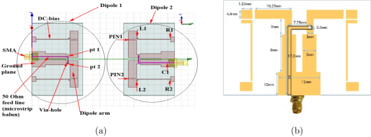
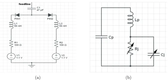
5.1 The Design and Geometry of the Proposed Antenna: (a) General view; (b) Dimensions of the Proposed Antenna Element . . . 44
5.2 Electrical circuits (a) Switching Circuit for PIN1 and PIN2 of the Antenna Element; (b) RF Equivalent Circuit for PIN diode including Packaging Effects . . . 45
5.3 Measured Antenna Parameters of one Antenna Element: (a) Return loss
(S11) (b) Voltage Standing-Wave Ratio (VSWR) . . . 48
5.4 Radiation Patterns of an Antenna Element: (a) Measured Elevation Pat-terns (left: E-plane Copolarization; right: E-plane Cross Polarization) (b) Measured Azimuthal Patterns (left: H-plane Copolarization; right: H-plane Cross Polarization) . . . 49
5.5 Envelope Correlation for two Collinear Quarter-wave Dipoles at different Frequencies . . . 50
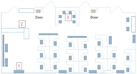
5.6 Office Layout for the Test Locations . . . 53
5.7 WiMAX Measurements: Percentile CINR Performance for the Reconfig-urable Antenna and the Commercial Antenna (a) Measurement Location (1) (b) Measurement Location (2) . . . 54
5.8 WiMAX Measurements: Percentile CINR Performance for the Reconfig-urable Antenna and the Commercial Antenna (a) Measurement Location (3) (b) Measurement Location (4) . . . 55
5.9 A Reconfigurable Alford Antenna . . . 57
5.10 Measurement Setup for the S-parameters (a) Configuration 1 (b) Config-uration 2 . . . 59
5.11 Envelope Correlation for two Collinear Quarter-wave Alfords at different Frequencies for different Configurations (a) decibel (dB) scale (b) Linear scale . . . 61
5.12 Average Envelope Correlation for two Collinear Quarter-wave Alfords at two Frequency bands for different Configurations . . . 62
6.1 System Model for MIMO-OFDM using Reconfigurable Antennas . . . 67
6.2 Switching Thresholds . . . 73
6.3 Computational Complexity Comparison . . . 78
6.4 Reconfigurable Printed Dipole Array (RPDA)[84] . . . 81
6.5 Radiation Patterns Combinations for a 2 Antenna Array System for all the Possible Antenna Configurations . . . 82
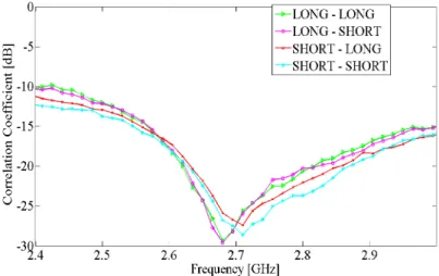
6.6 The Measured Correlation Coefficient as a Function of Resonant Frequency for the LONG and SHORT Configurations in a 2 Element Array with
inter-element Separation of λ/4 . . . 82
6.7 An Experimental Communication Node or Station . . . 83
6.8 Measured Channel Magnitude over time per Subcarrier . . . 84
6.9 Empirical ppSNR CDFs for Reconfigurable AMC and Non-Reconfigurable AMC. . . 87
6.10 Throughput Comparison for 2x2 MIMO-OFDM System . . . 87
6.11 BER Performance Comparison . . . 88
6.12 The Distribution of Modulation use in SAMC . . . 88
6.13 Configurations Usage in the Proposed Algorithm . . . 89
6.14 Channel Variation over time as Measured using the active Antenna Con-figurations . . . 89
7.1 A Graphical Representation of a Single Link WINNER Cluster Model [120] 94 7.2 Measurement Setup for the S-parameters (a) Configuration 1 (b) Config-uration 2 [128] . . . 99
7.3 Antenna Envelope Correlation for two Collinear Quarter-wave Alfords at different Frequencies for different Configurations in decibel (dB) . . . 100
7.4 Correlation Coefficient of two Antenna Elements for using Laplacian PAS . 103 7.5 The CCDF of Capacity for a 2×2 MIMO/MEA using Conventional and Reconfigurable Arrays for an SNR of 20dB . . . 104
7.6 The Diversity Gain CDFs for the a 2×2 MIMO/MEA System in Conven-tional and Reconfigurable Array Modes . . . 105
7.7 Conventional Antenna Array System: Closed-loop Single User MIMO Transmission System using Code-book-based Precoding and Antenna Grouping . . . 106
7.8 Reconfigurable Antenna Array System: Closed-loop Single User MIMO
Transmission System using Code-book-based Precoding . . . 106
7.9 Average Capacity for Single User MIMO Transmission System; Shannon Capacity, Waterfilling Technique, Antenna Selection Approaches, Pattern Diversity Scheme . . . 113
8.1 A Schematic of a Generalized Functional Software Defined Radio . . . 119
8.2 USRP: (a) Hardware; (b) Block Diagram of Internal Features of USRP . . . . 121
8.3 GNU Radio Framework: (a) A High-level Architecture of GNURadio-Based SDR; (b) GNU Radio Stacks . . . 123
8.4 A Protocol Stack for the SDR Testbed based on Open Source Software . . . . 124
8.5 A High level Schematic of the GENI WiMAX System and its Interfaces . . . 126
8.6 A High level Schematic of the Proposed Testbed . . . 129
8.7 WiMAX Setup Architecture . . . 131
8.8 Downlink Throughput Performance against CINR . . . 133
8.9 Downlink Modulation Usage Performance . . . 134
8.10 Downlink Performance of Throughput versus PER . . . 135
8.11 Uplink Throughput versus PER Performance . . . 135
Abstract
Pattern Diversity Characterization of Reconfigurable Antenna Arrays for Next Generation Wireless Systems
George Dimanson Sworo
Advisors: Kapil R. Dandekar, Ph.D. and Moshe Kam, Ph.D.
The use of multi-antenna technology in wireless radio communications has at-tracted tremendous attention due to its potential to increase data rates without re-quiring additional bandwidth and transmission power. This has been driven by the burgeoning demand for high data rates and the need for instantaneous and ubiquitous access to information. It is therefore no surprise that current and future generation wireless standards such as LTE and WiMAX have adopted the use of adaptive multi-antenna systems also known as adaptive Multiple Input and Multiple Output (MIMO) as their de facto transmission technology.
In this thesis work, we focus on the design of a smart wireless antenna system, and the study of relevant techniques that enable us to reap the benefits of their de-ployment in small wireless devices with MIMO capability. Specifically, we employ a new class of adaptive antenna systems known as Reconfigurable Antenna Systems (RAS) for portable devices. These antennas are capable of dynamically changing their electrical and radiation characteristics to suit the conditions of the wireless channel. The changing radiation patterns lead to pattern diversity gains that improve system performance. This is in contrast to conventional non-reconfigurable arrays which de-pend on signal processing techniques such as antenna grouping and beamforming to achieve performance gains. However, despite the demonstrable system-level perfor-mance benefits of RAS in adaptive MIMO, few of these antennas have been adopted and integrated in state-of-the-art wireless standards. Their usage has been partly
inhibited by the prohibitive costs of implementation and operation in a real wireless infrastructure.
As part of this thesis research effort we attempt to integrate these new antennas into a cost-effective real wireless MIMO testbed for use in current generation tech-nologies. The solution integration is carried-out through the use of readily available software-defined radio frameworks. We first design, analyze and characterize the pat-tern diversity in RAS antenna arrays that resonate at frequencies suitable for 4G applications. We then study the benefits of pattern diversity obtained from RAS arrays over conventional space diversity approaches such as antenna grouping and beamforming. This dissertation also presents low-complexity adaptive physical layer models and algorithms to exploit the benefits of RAS array integration in MIMO wire-less systems. We implement these algorithms in software-defined radio frameworks, experimentally test, and benchmark them against other established approaches in literature. And finally, integrate and test these RAS array design prototypes as part of the MIMO wireless system that leverages a state-of-the-art wireless base station and mobile terminals.
CHAPTER 1: INTRODUCTION
In wireless radio communications, multivariate channel factors can cause signal strength attenuation and degradation, which can adversely affect the quality of com-munications. These channel impairments are a result of signal transmissions over a wireless channel - a logical radio link or medium that connects a data source and a data sink - that is used to convey the information signal. A defining characteristic of the wireless channel is the variation of the channel strength or state over time and over frequency [1].
Figure 1.1: Transmission over a Wireless Channel (Adapted from [2]).
Fig. 1.1 depicts the propagation of a signal over a wireless channel between the transmitter (located at the top left) to the receiver (at the bottom right). It illus-trates the possible paths traversed by a signal in a typical indoor channel
environ-ment. These paths are influenced by various channel impairment sources such as a microwave, which introduces interference; walls, which introduce shadowing; reflective or obstructive surfaces that causes multipath fading [3].
1.1 Motivation and Problem Statement
The performance of a system in a wireless environments that experiences fading due to multipath propagation is often affected by the spatial distribution of the multi-paths. These multipaths are multiple wavefronts that can cause random variations in the signal strength. This effect leads to a channel phenomenon called spatial selectiv-ity. Traditionally, spatial selectivity causes the signal power to fluctuate rapidly over time and distance and can lead to multipath fading. This multipath fading– a pitfall of wireless transmission– can be turned into a benefit by using multi-antenna systems. Multi-antenna systems also known as MIMO can effectively take advantage of these random fading, to increase data rates and link reliability (reduced fading) [4] without requiring additional bandwidth or increased transmit power. These systems leverage the spatial characteristics of the multipath channel to achieve spatial diversity or gain by placing seperate antennas in the dense multipath environment. The multiple antennas can then be used to simultaneously transmit independent data streams over the channel to increase data rate. MIMO spreads the same total transmit power over the antennas to achieve array gain that improves the spectral efficiency (thus, more bits per second per hertz of bandwidth) [5] – [7]. The spatial diversity can also be achieved by combining the signals from separate antennas to maximize the resultant signal amplitude.
However, when the channel consists of few multipaths, the measured signals at the different antennas of the multi-antenna system can become spatially correlated. Spatial correlation–a correlation between the signal’s spatial direction and the
av-erage received signal gain –degrades the performance of multi-antenna systems and limits the number of antennas that can be used for a given MIMO link. For this reason, MIMO antenna arrays must be designed to reduce spatial correlation to yield the additional degrees of diversity and improve system performance [155]. Moreover, the design and analysis of multi-antenna arrays is coupled to the physical layer ca-pabilities of the MIMO system. This dependency is due to the fact that the physical layer depends on signal processing algorithms that operate on the multivariate prop-agation channel characteristics that determines the performance of the MIMO arrays. Specifically, spatial correlation is a function of both spatial characteristics such as an-gular spread, the number of scatterers, and antenna array parameters including the antenna geometry, element spacing and pattern, polarization, and mutual coupling [153]. These variables in-turn affects the performance of the physical layer signal processing techniques.
1.1.1 Brief Overview
Various research efforts in [5], and [7]–[10] have established that adaptive antenna wireless systems increase spectral efficiency and provide flexible data rates in mul-tipath fading channels. These systems employ MIMO technology and use multiple antennas at both the transmitter and the receiver to improve signal reception and transmission rates. This is why MIMO technology have become an integral part of the fourth-generation (4G) wireless communication standards such as WiMAX, Long-Term Evolution (LTE) and beyond.
Typical MIMO systems employ multiple antenna elements at both the transmitter and the receiver. These elements can either be co-located and coupled via a controller as part of an array or are physically separated from each other. The use of arrays have been demonstrated to improve signal transmission range and reliability,
how-ever, arrays require large spacing and complex signal processing; these constraints render them impractical to deploy in portable wireless devices such as routers or ac-cess points. This limitation motivated research efforts in the design of a compact alternative antenna solution for small devices: a single antenna structure that can act as a multiple element array.
This dissertation focuses on a new class of adaptive antenna array systems known as Reconfigurable Antenna Systems. These reconfigurable antenna technology has been shown to offer performance gains in MIMO systems by increasing channel ca-pacity [10] and Signal-to-Noise Ratio (SNR) [9] at the Receiver. RAS antennas offer the following benefits:
• These antennas are capable of dynamically changing their radiation patterns and enable MIMO systems to adapt to physical link conditions.
• RAS provide space and cost benefits in incorporating multiple elements in a single physical device [11], and by reducing the number of RF chains [112], [13]. • These antennas have been used to improve advanced interference management
techniques like interference alignment [14].
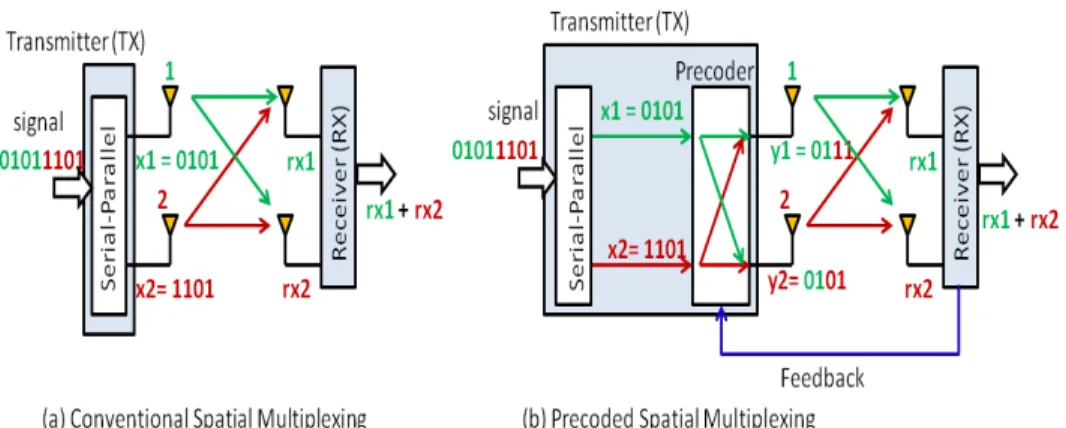
Fig. 1.2 illustrates the fundamental differences between a standard MIMO sys-tem, a MIMO system equipped with Adaptive Antenna Arrays (AAA) and with reconfigurable antennas. Fig. 1.2(a) depicts a standard MIMO system that uses spa-tial multiplexing technology where different data is sent on the same time-frequency resource from different antennas so that spectrum efficiency is multiplied without expending more frequency resource. Fig. 1.2(b) compares and contrasts a MIMO system that uses antenna grouping algorithms for signal processing with one that employs reconfigurable antennas. In the first case (left of Fig. 1.2(b)) , antennas are grouped into sub-arrays and a hybrid of beamforming and spatial multiplexing
techniques is used for signal processing. Beamforming leverages the fact that ev-ery physical antenna within the sub-array transmits the same signal and performs a weighted processing on each antenna element in the sub-array to steer the transmit beam to the target receiver. The spatial multiplexing aspect is then realized from the use of multiple sub-arrays to send independent data streams. The second scenario (right of Fig. 1.2(b)) leverages the pattern diversity of the reconfigurable antennas to affect how the transmitter or receiver perceives the wireless channel. The transceiver pair is provided with a range of channel paths to select or adapt in order to enhance performance.
In addition to adapting antenna arrays or radiation patterns of its transceivers to the channel conditions, such a MIMO systems can also leverage physical layer link adaptation techniques to improve transmission rate and bit error rates. Link adaptation simply refers to a set of techniques where modulation, coding, and other signal transmission parameters are changed on the fly to better adjust to the changing channel conditions. The literature on link adaptation or Adaptive Modulation and Coding (AMC) is vast. However, the representative approaches found in [15]–[19] have demonstrated that adaptive modulation and coding systems exhibit great per-formance enhancements compared to systems that do not exploit the quality of the radio channel.
1.2 Problem
Although reconfigurable antennas have been in development for the last 30 years, few are in use. From the system perspective, the benefits and costs of implementa-tion of reconfigurable antennas are unclear from a system perspective. “System and operating environment complexity makes it difficult to identify a particular antenna functionality that will automatically result in greater throughput, higher link
relia-(a) Standard MIMO
(b) MIMO System with Adaptive Antenna Array and Reconfigurable Antennas
Figure 1.2: Standard MIMO System versus a MIMO System with Reconfigurable Antennas (Adapted from [8]).
bility, or lower bit error rates [20].” Also, the concept of reconfigurability was initially designed for frequency switched antenna systems but has also been slowly adopted for pattern reconfigurability – although the concept has not yet been fully accepted. To date, a lot of the research effort in MIMO antenna arrays have either sepa-rately focused on developing techniques that uses conventional antennas as adaptive arrays [21] – [23], or building compact reconfigurable antenna arrays for adaptive MIMO as an alternative to conventional arrays [20] – [26]. A few quantitative studies have also considered the system-level performance benefits of antenna
reconfigurabil-ity [9], [10] and [112]. These works are however limited to simulation studies rather than practical implementations in a real-time MIMO system. Their approaches also decouples the design of the reconfigurable antenna arrays from that of the physical layer signal processing. And in so doing fail to take full advantage of multi-antenna systems when applied in spatially correlated channel environments. As already es-tablished, spatial correlation degrades the performance of multi-antenna systems by limiting the number of antennas that can be used for a given MIMO link. Also, the dependence of spatial correlation on both spatial characteristics of the channel and antenna array parameters such as antenna geometry and pattern, requires a different design approach.
In this thesis work we attempt to bridge the gap between the concept and theory of reconfigurable antenna array systems and their practical integration in a wireless communication system. We integrate working prototypes of pattern-reconfigurable antenna arrays in a 4G wireless framework and implement relevant physical layer algorithms that leverage their capabilities. Our design technique couples the design of the reconfigurable antenna arrays with the physical layer signal processing algorithms to improve system performance. Specifically, a system-level implementation of a MIMO physical layer model that leverage the capabilities of reconfigurable antennas is carried out in concert with various signal processing and link adaptation algorithms. The algorithms are designed and developed with computational efficiency in mind in order to optimize the performance benefits of these antenna arrays.
Among the myriad of MIMO signal processing techniques, approaches that take advantage of spatial multiplexing, spatial diversity, Beamforming or spatial filtering, were implemented and benchmarked against other works in literature. Notably, the approaches in [21], [23], and [104] which employ spatial multiplexing and transmit beamforming, antenna grouped algorithms are implemented. The work in [21]
pro-poses a multimode antenna selection algorithm that dynamically adjusts both the number of substreams and the mapping of substreams to antennas, for a fixed data rate, to the channel conditions. It also discusses a dual-mode selection algorithm that switches between spatial multiplexing and beamforming. It also derives several ex-pressions that characterize the various criteria for selecting the number of substreams and the optimal mapping of substreams to transmit antennas. In [23], an adaptive algorithm that selects between beamforming, multimode antenna selection and spa-tial multiplexing is presented. This model extends the work in [21] to demonstrate capacity gains derived from adaptively switching between MIMO schemes. The work in [104] introduces several mode selections criteria and a low complexity criterion which is derived from a low complexity antenna grouping algorithm.
However, all these works employ conventional antenna arrays and limited attempts have been made to implement pattern reconfigurable antenna arrays. The proposed model in this dissertation leverages the pattern diversity derived from using reconfig-urable antenna arrays to improve system performance in lieu of conventional antenna arrays approaches.
1.3 Contributions
The main implication of our work is the demonstration of the benefits of pattern reconfigurable antenna arrays to motivate their integration in portable MIMO wireless systems – systems that are too small to employ conventional antenna arrays due to space/design limitations. This integration is possible due to the fact that a single reconfigurable antenna structure is used to act as a multiple element array in lieu of several physical antenna elements. Other contributions of this dissertation are summarized below:
that resonate in the frequency band between 2.5 – 3GHz for application in next generation wireless systems.
• Demonstrate and benchmark the benefits of pattern diversity derived from reconfigurable antennas through an exhaustive study of the spatial param-eters and characteristics that affects MIMO array wireless transmissions. Specifically, the effects of spatial correlation on the performance of recon-figurable antenna systems against that of conventional arrays derived from techniques such as antenna grouping; this is motivated by the dependence of spatial correlation on both spatial characteristics such as angular spread, the number of scatterers, and antenna array parameters including the an-tenna geometry, element spacing and pattern, polarization, and mutual coupling
• Analyze the performance of these pattern reconfigurable antennas as an integral part of a WiMAX/LTE system through field testing and bench-mark their performance against that of conventional commercial antenna arrays. Part of this work is published in [27]
2. Implement an adaptive system-level physical layer model for MIMO array sys-tem that leverage the capabilities of reconfigurable antennas and wireless trans-mission architectures such as OFDM, spatial multiplexing and precoding.
• Experimentally benchmark the proposed model against some simulation-based quantitative models that use antenna grouping in lieu of RAS • Propose a low complexity adaptive algorithm for joint antenna state or
configuration selection and link adaptation based on post processing SNR (ppSNR) as a performance metric and is published in [118] and [29].
3. Integrate pattern reconfigurable antennas into a 4G wireless system, specifically WiMAX/LTE platform.
• Benchmark the performance of reconfigurable antennas with conventional commercial antennas for WiMAX/LTE applications. Part of this work appears in [27] and [30]
1.4 Organization
This thesis is organized as follows: Chapter 2 discusses the motivation for adaptive multi-antenna communication systems and introduces adaptive antenna array systems known as reconfigurable antenna arrays for MIMO communications.
Chapter 3 provides an overview of MIMO communication architectures and trans-mission techniques used in concert with MIMO signal processing. The concept of BLAST transmission for multi-antennas processing is first introduced, followed by a discussion of the relevant detection/decoding algorithms used in a MIMO system employing V-BLAST.
Chapter 4 presents the principle of MIMO-OFDM transmission for wireless trans-missions in frequency selective wireless channels as the system model for next gener-ation technologies.
Chapter 5 introduces the design of a pattern reconfigurable antenna arrays for applications that operate in the frequency band between 2.5–2.7 GHz. The antenna specifications and design methodology are described, followed by a presentation of some experimental results.
Chapter 6 proposes a joint antenna state selection and link adaptation algorithm that leverages the capabilities of reconfigurable antennas and adaptive modulation to increase throughput in MIMO-OFDM systems. Field experimentation results for the implementation of a 2x2 MIMO-OFDM system in a Software Defined Radio (SDR)
framework are presented. Chapter 7 presents a system-level implementation of several MIMO approaches in the SDR framework presented in Chapter 6. Chapter 8 presents a platform for integrating pattern reconfigurable antennas in next generation systems. Chapter 9 provides a summary of this thesis work and contributions, including the future work.
CHAPTER 2: ADAPTIVE MULTI-ANTENNA COMMUNICATIONS SYSTEMS
In theory, the performance of wireless communication systems can be improved by using multiple antennas for signal transmission and reception. Ideally, the prop-agation channels between each transceiver antenna pair are statistically independent and identically distributed (i.i.d); this enables the generation of multiple independent channels with identical characteristics by precoding, which, can be used for either transmitting multiple data streams or increasing the reliability. Realistically, how-ever, the channels between different antennas are often correlated and therefore the potential multi-antenna gains may not be obtainable [31], [32]. Spatial correlation - a correlation between the signal’s spatial direction and the average received signal gain - degrades the performance of multi-antenna systems and limits the number of antennas that can compactly be squeezed on a device. This is because it decreases the number of independent channels that can be created by precoding [33], [156]. However, rich multipath propagation decreases the spatial correlation by spreading the signal such that multipath components are received from many different spatial directions [155]. This is the reason why recent research in this field has focused on the development of adaptive antenna systems that exploit multipath propagation to mitigate the effects of wireless channel fading or fluctuations. In this chapter we in-troduce a new class of adaptive antenna systems and the techniques commonly used to leverage their capabilities in multi-antenna communication.
2.1 Adaptive Antenna Array Systems
The term “Adaptive Antenna” was first used to describe a self-phasing antenna system which reradiates a signal in the direction from which it was received [36]. The adaptive aspect stems from the fact that it performs without any prior knowledge of the direction in which it is to transmit. Generally, an Adaptive Antenna System (AAS) can focus it’s transmit energy to the direction of the receiver and, while re-ceiving, it can focus the energy to the direction of the transmitter. The technique used for this purpose is known as Beamforming or Beamsteering or Beamshaping; it works by adjusting the width and the angle of the antenna radiation pattern or beam. AAS systems often employ adaptive arrays – a number of antenna elements coupled together via a controller – to exploit the spatial dimension in signal processing to improve system operating parameters: such as capacity, quality, coverage and cost. They make use of these adaptive arrays to allow the antenna to steer the beam to any direction of interest while simultaneously nulling interference [37]. The direction of the signal beams is estimated using the direction-of-arrival (DOA) estimation meth-ods [38]. Fig. 2.1 illustrates the use of an adaptive antenna array for beamforming in a mobile network.
2.1.1 Reconfigurable Antenna Systems (RAS)
Reconfigurable Antenna Systems [39]–[45] are a new class of adaptive antenna sys-tems that dynamically tune their electrical or radiation characteristics in response to multivariate wireless channel fluctuations. These antennas are capable of dynamically changing their radiation patterns, polarization states, and frequency of operation to accommodate the operating requirements [8]. Recently, different solutions employing various techniques for reconfiguring the radiation characteristic have been proposed. These techniques fall under one of these categories:
Figure 2.1: Using Adaptive Antenna Array for Beamsteering (Adapted from [38]).
(i) Pattern Diversity: exploits the difference in radiation pattern between two or more co-located antennas (array) to decorrelate the sub-channels of the link [116]. “This technique helps to achieve independent fading by transmit-ting/receiving on different signal paths at each antenna. In the ideal case each array element has a radiation pattern that points in a direction different from all the others in order to capture signals that are uncorrelated from those collected at the other elements [8].”
(ii) Spatial Diversity: uses multiple antennas that are physically separated in space and exploits the phase delay between the antennas to decorrelate the fading sig-nals [47]. This technique requires a minimum spacing between antenna elements depending on the environment and the width of the multipath angle of arrival.
This scheme allows multiple users to share a limited communication spectrum and avoid co-channel interference.
(iii) Polarization Diversity: uses antenna array with orthogonal polarizations. The benefit of this scheme is the ability to use antennas located in the same place, unlike spatial diversity. The work in [48] demonstrates the impact of polarization diversity on sub-channel decorrelation and channel capacity in MIMO systems.
Bried Review of Related Works in Reconfigurable Antennas
The literature of reconfigurable antennas is vast and still growing. Several works in [166]–[169] have proposed reconfigurable antennas that are reconfigurable in fre-quency. These works design and characterize radio frequency microelectromechanical (RF-MEMS)-based reconfigurable antennas that operates in multiple frequencies for various application. The reconfigurability between the modes is achieved by using RF MEM switch technology, which enables changing antenna length and electrical properties, thereby the resonance frequency. However, despite the excellent switch-ing characteristics of the MEMS technology, the reliability and packagswitch-ing of these switches is problematic and their power handling capability is limited.
For application in mobile communications, the works [159], [160], and [161], [43], and [45] have leveraged polarization, spatial, and pattern reconfigurable antennas to improve link reliability in wireless communications. While other research works in [170]-[171] have developed reconfigurable antennas for laboratory on chip applications in the medical field. Their antenna reconfiguration mechanism rely on electrowetting based on digital microfluidics to implement a frequency reconfigurable antenna.
The wireless laboratory at Drexel University has focused on designing, testing and fabricating pattern reconfigurable including
can be reconfigured in length using PIN diode switches. The switch configura-tion can be modified in a manner that is adaptive to changes to the environment. This antenna is normally developed as part of an array whose elements are a quarter of a wavelength apart. The configuration of switches then affects the mutual coupling between the array elements, and subsequently, the radiation pattern of each antenna element. This leads to different degrees of pattern diversity that can be used to improve link capacity ;
(ii) Reconfigurable radius circular patch antenna [39], [40]: it is based on a standard circular patch antenna design and enables a single antenna element to be used as a two element array by using multiple feed points. By exciting different electromagnetic modes and varying the size of the circular patch antenna as well as the feed location, different polarization and radiation patterns cane be generated at the far-field. These antennas exploit the techniques of pattern and polarization diversity to increase the diversity level of the system and the amount of received signal power ;
(iii) Reconfigurable length spiral antenna [41]: This antenna structure consists of a single arm Archimedean spiral whose arm length can be reconfigured using PIN diode switches. The length variation excites different radiation patterns at the same frequency of operation.;
(iv) Reconfigurable leaky wave antenna [42]: This is a composite right left handed (CRLH) microstrip structure that incorporates varactor diodes for fixed-frequency voltage-controlled operation. Beam scanning is achieved by modulating the ca-pacitance of the structure by adjusting a bias voltage applied to the varactors. Each excitation bias voltage generates a different radiation pattern that can be used to improve diversity.
In this thesis, we use reconfigurable adaptive antenna arrays that leverage pattern diversity to improve system performance. Specifically, we design and characterize pattern reconfigurable microstrip arrays based on a reference design for 4G appli-cations. We investigate the benefits offered by radiation pattern diversity in these reconfigurable antenna arrays. Our motivation for these antenna arrays stems from the findings of previous studies, which have shown that the capacity of conventional multi-element arrays (MEAs) is adversely affected by spatial correlation–as a result of both spatial channel characteristics and antenna array geometry and radiation pat-terns. However, the design flexibility of pattern reconfigurable antenna arrays enables us to exploit the antenna geometry and mutual coupling between radiating array el-ements to generate uncorrelated channels. This results in pattern diversity that can improve capacity and offer a unique opportunity for antenna system miniaturization for portable wireless devices.
CHAPTER 3: MIMO COMMUNICATION ARCHITECTURES AND TECHNIQUES
Even though the benefits of antenna arrays for MIMO communication have been demonstrated in [10], [41], [49] and several other efforts, the full advantages of these arrays are dependent on the use of MIMO processing and transmission techniques. This fact is especially crucial for adaptive antenna arrays like reconfigurable antenna arrays that rely on shift processing and implementation. The tremendous potential and impact of MIMO processing on capacity increase was reported in [6], [7], and [50]. However, in order to design efficient communication algorithms for MIMO systems and to understand the performance limits, it is also important to understand the nature of the channel. In this chapter we present an overview of MIMO signal pro-cessing architectures and the relevant transmission techniques used in concert with them.
3.1 MIMO Transmission Architectures
As briefly discussed in Chapter 1, numerous theoretical investigations have demon-strated that the multipath wireless channels can be exploited using MIMO systems to improve channel capacity. However, these capacity benefits can only be realized through the use of appropriate MIMO processing architectures [5] and [51]. These approaches are commonly known as BLAST (Bell Laboratories Layered Space-Time) architectures and have become the de facto reference architectures for high perfor-mance MIMO systems. The BLAST architecture utilizes multi-element transmit and receive arrays to provide high capacity wireless communications. In rich multipath environment that experiences Rayleigh scattering, the BLAST structure leads to
the-oretical rates which grow linearly with the number of antennas for a system that em-ploys equal number of transmit and receive antennas. These rates have been shown to approach the Shannon capacity limit in [52]. Two types of BLAST architectures have been widely publicized: D-BLAST [5] and V-BLAST [51]. In this section we present a brief overview of the D-BLAST architecture and provide a more detailed treatise of V-BLAST. We utilize the V-BLAST processing structure for implementation of a realistic MIMO communication system presented in [118] as part of this thesis work.
3.1.1 D-BLAST Transmission
Figure 3.1: D-BLAST Transmission Technique/Diagonal Encoding (Adapted from [53]).
D-BLAST which stands for diagonal BLAST (D-BLAST), is a diagonally-layered space-time architecture proposed by Foshchini in [5]. In this architecture, the infor-mation bit stream from the source is first demultiplexed (at the Demux block) into
several Q substreams – one stream per transmit antenna. Each substream is sepa-rately encoded, interleaved and mapped to complex symbols (refer to Fig. 3.1 (a)). Before going to the antenna, the signal substream is rotated in a round-robin fash-ion so that the bit-substream and antenna associatfash-ion is periodically recycled [53]. The symbols of each substream are dispersed diagonally across antennas and time as illustrated in Fig. 3.1 (b).
Each block in Fig. 3.1 (b) represents a transmitted symbol. A layer consists of Q consecutive blocks with the same color. Each layer is represented with a different shade and runs diagonally through the antenna elements as time progresses. Rather than commit each data substream to a single antenna, the D-BLAST ensures that none of the layers misses out because of a poor transmission path. However, one draw back of this layered approach is that it introduces space time wastage where no transmission can take place. But because the symbols are spread across antennas, the scheme captures transmit diversity.
At the receiver, the decoding is performed layer-by-layer since each diagonal layer constitutes a complete code word. D-BLAST uses a detection strategy that combines interference cancellation and suppression. This is to yield a symbol vector that is free of interference from all signals that were simultaneously transmitted from the other antennas. As depicted in Fig. 3.1 (b), the entries below the first diagonal layer is empty or zeros; this is illustrated by the wasted space-time. “To decode the first diagonal layer, the receiver generates a soft-decision statistic for each entry in that diagonal. In doing so, the interference from the upper diagonals is suppressed by projecting the received signal onto the null space of the upper interfaces. The soft statistics are then used by the corresponding channel decoder to decode this diagonal. The decoder output is then fed back to cancel the first diagonal contribution in the interface while decoding the next diagonal [53].” The rest of the diagonal layers are
decoded in the same manner.
3.1.2 Vertical BLAST (V-BLAST) Transmission
Figure 3.2: Vertical Encoding or V-BLAST System (Adapted from [53]).
The vertical BLAST is a variant of the diagonal approach and tries to reduce the computational complexity of the D-BLAST architecture by using simplified encoding [51]. As in D-BLAST, a single data stream is demultiplexed into Q substreams, how-ever, in V-BLAST the bit stream is encoded, interleaved and mapped into symbols before being fed to the demultiplexer. VBLAST uses vertical encoding – each infor-mation symbol can be spread across all antennas and the layers are coupled; thus, there is no rotation of substreams as in D-BLAST. Diversity is improved since the transmission is spread over all transmit antennas and each substream is received by all receiving antennas.
en-coding in D-BLAST, but loses the transmit diversity because each stream goes over only one antenna. Fig. 3.2 illustrates the V-BLAST system. The transmitters are conventional QAM transmitters and operate cochannel at symbol rate 1/T symbols, with synchronized symbol timing. Receivers 1–P are also ordinary QAM receivers that operate cochannel (radio transmission occurs on the same frequency channel), each receiving the signals radiated from all Q transmit antennas.
At the decoder, V-BLAST implements a nonlinear detection technique based on Zero Forcing (ZF) combined with symbol cancellation to improve performance. Note, ZF is an equalization algorithm which applies the inverse of the frequency response of the channel to the received signal, to restore the signal after the channel. The key idea in the signal detection is to look at the signals from all the receive antennas simultaneously. This process is done by first extracting the strongest substream from the received signals, and then proceeding with the weaker signals; decoding the weaker signals is made easier since it is done after the strongest substream has been removed as a source of interference [53]. The process is known as Successive Interference Cancellation (SIC); and is similar to decision feedback equalization. The ordering of the substreams becomes important for the overall system performance when symbol cancellation is used. Ordering determines the post-detection SNR and the transmitted symbol with the smallest post-detection SNR ultimately dominate the error performance of the system. We will discuss V-BLAST detection or decoding process in more detail, shortly; but for simplicity we base our explanation on the generic MIMO system in Fig. 3.3.
A Generic MIMO Channel using V-BLAST Architecture
Consider a generic discrete-time MIMO system in Fig. 3.3 with Q antennas at the transmit side (TX) and P antennas receiver side (RX). The MIMO channel at a
Figure 3.3: MIMO Transmission System using VBLAST
given instant is represented as a PxQ matrix H.
H= H1,1 H1,2 ... H1,Q H2,1 H2,2 ... H2,Q ... ... ... ... HP,1 HP,2 ... HP,Q .
where Hp,q is the channel gain between the pth receive and qth transmit antenna pair. The qth column of H is the spatial signature of the qth transmit antenna across the receive antenna array. “The relative geometry of the Q spatial signatures determines the distinguishability of the signals launched from the transmit antennas at a receiver. This is important when independent data streams are launched from the transmit antennas, as in spatial multiplexing [54].”
For a frequency-flat fading – the delay spread in the channel is negligible compared to the inverse bandwidth – MIMO channel, the discrete-time signal relationship over
a symbol period is modeled by :
y=
s
Ex
QHx+z (3.1)
where y is the Px1 received signal vector, x is the Qx1 transmitted signal vec-tor, z is the temporally Additive White Complex Gaussian Noise (AWGN) with E[zzH] = N
oIP and variance σ2; (.)H denotes the hermitian transpose. Ex is the total average energy available at the transmitter over a symbol period after all losses due propagation and shadowing have been removed. It is assumed that the covariance matrix of x,Rxx =E[xxH] and satisfies T r(Rxx) = Q. The ratio ρ=Ex/No is SNR per receive antenna. Furthermore, channel block fading – the channel time variation is negligible over L consecutive symbol periods (determined by the coherence time) [55]. Also, the transmitters are conventional QAM transmitters and operate cochan-nel at symbol rate 1/T symbols, with synchronized symbol timing. Receivers 1–P are also ordinary QAM receivers that operate cochannel, each receiving the signals radiated from all Q transmit antennas.
Implementing V-BLAST Detection: Zero-Forcing decoder
Suppose x = (x1, x2, ..., xQ)T denote the vector of transmit symbols. Then, the corresponding received P-vector yis given by (3.1). Since the processing takes place at the receiver where, under assumption the channel matrix H is invertible, H is inverted and the transmitted MIMO vector xis estimated by the ZF decoder as
xest =H−1x (3.2)
Conceptually, the ZF principle is based on a conventional Adaptive Antenna Array technique known as linear combinatorial nulling [56]. In this technique, the detection
algorithm starts by considering each substream as the desired signal, and the remain-der as the interferers. Nulling is performed by linearly weighting the received signals such that all interfering terms are canceled. For Zero-Forcing, nulling is performed by selecting 1xQ dimensional weight vectors wi, i= 1,2, ..., Q, referred to as nulling vectors [56], such that it satisfies
wTi (H)q = 0, q6=i 1 q=i (3.3)
where (H)q is theq-th column of Hand q= 1,2, ..., Q, denoting theqthtransmitter. The decision statistic for the i−th substream is therefore ri =wTi y.
For simplicity, let wi be the ith row of a matrix W, then it follows that
WH=IP, (3.4)
where W is a matrix that represents the linear processing in the receiver. So, by forcing the interferers to zero, each desired element of x can be estimated. If H is not square, W equals the pseudo-inverse of H (denoted byH†) given by
W=H†= (HHH)−1HH. (3.5)
The pseudo-inverse exists when Q ≤ P and all elements of H are assumed to be i.i.d. For Q > P, HHH is singular and its inverse does not exist. When the
pseudo-inverse exists, the estimates of x (given by xest) is derived as follows
One disadvantage of using Zero-Forcing is that it suffers from noise enhancements – it will amplify the noise by a large factor and destroy the signal power– especially for channels with a high condition number (HHH). For this reason, V-BLAST detection combines ZF nulling with symbol cancellation or Successive Interference Cancellation (SIC) – the interference from the already-detected components of xis subtracted out from the received signal vector; resulting in a modified received vector in which, fewer interferers are present [51].
When SIC is used, the order of detection of the substreams or the components of x becomes important for system performance. Applying SIC with optimal ordering ensures that the reliability of the symbol which is decoded first is guaranteed to have a lower error probability than the other symbols. This lowers the chances of making incorrect decisions with the other symbols, and therefore lowers the overall error rate of detection. For our discussion, let the ordered set
ζ ≡ζ1, ζ2, ..., ζQ (3.7)
represent a permutation of the integers 1,2, ..., Q specifying the order in which com-ponents of the transmitted symbol vector x are extracted. The general detection process for the V-BLAST structure proceeds as follows:
Step 1: Using nulling vector wζ1, form a linear combination of the components
of y to yield a decision statistic rζ1:
rζ1 =w
T
ζ1y (3.8)
Step 2: Slice rζ1 to obtain ˆxζ1:
ˆ
where sgn(.) denotes the quantization (slicing) operation appropriate to the constel-lation in use.
Step 3: Assuming that ˆxζ1 =xζ1, cancel xζ1 from the received vector y; resulting
in modified received vector y2:
y2 =y−xζˆ1(H)ζ1 (3.10)
where (H)ζ1 denotes the ζ1th column of H. Steps 1 to 3 are then performed for
components ζ2, ..., ζQ by operating in turn on the progression of modified received vectors y2,y3, ...,yQ.
Note, the ζith ZF nulling vector is defined as the unique minimum norm vector satisfying wTζ i(H)ζq = 0, q ≥i 1 q =i (3.11)
Thus, the ζith ZF nulling vector, wζi, is orthogonal to the subspace spanned by
the contributions to yi due to those symbols not yet estimated and canceled. It can be shown that the unique vector in (3.11) is just the ζith row of H±ζi−1, where the
notation H−ζi denotes the matrix obtained by zeroing columns ζ1, ζ2, ..., ζi of H and+
denotes the Moore-Penrose psuedoinverse [57].
The full ZF V-BLAST algorithm detection algorithm is a recursive procedure, including determination of the optimal ordering and is given by Algorithm 1below [51]:
Algorithm 1 ZF V-BLAST Detection Algorithm 1: initialization: 2: i←1 3: G1 =H+ 4: ζ1 = arg maxq||(G1)q||2 5: recursion: 6: wζi = (G1)ζi 7: rζi =w T ζiyi 8: xˆζi =sgn(rζi) 9: yi+1 =yi−xˆζi(H)ζi 10: Gi+1 =H±ζi 11: ζi+1 = arg maxq /∈ {ζ1,...,ζi}||(Gi+1)q|| 2 12: i←i+ 1
3.2 MIMO Signal Processing Techniques
MIMO technology can be implemented using different signal processing tech-niques. These techniques have varying characteristics and are used for different sce-narios. This section briefly introduces a handful of these multi-antenna technologies by analyzing various technical features and their application scenarios.
3.2.1 Spatial Multiplexing (SM)
In spatial multiplexing, multiple independent signals are transmitted over the same frequency at the same time. Thus, different data signals are sent on the same time-frequency resource from different antennas so that spectrum efficiency is mul-tiplied without expending more frequency resource. Therefore, if the SM system consisting of Q transmit antennas and P receive antennas is used, then the maxi-mum number of independent signals that can be transmitted is min{Q, P}. This is illustrated in Fig. 3.4(a). A spatial multiplexing system may be arranged in different ways: In the downlink channel, the P receive antennas may belong to the same user or may be used by P different users. Similarly, in the uplink, the transmit antennas
may either belong to the same user or different users. The availability of CSI, can help choose the best subset of transmit antennas in the case where all Q antennas are used by a single user or help select the best subset of users when the transmit antennas belong to different users.
Precoded Spatial Multiplexing (SM)
In point-to-point MIMO systems, precoded SM means that multiple data streams are emitted from the transmit antennas with independent and appropriate weightings such that the link throughput is maximized at the receiver output. In this usage, precoding refers to the process of prearranging the transmit signals in consideration of the channel state in such a way that the receiver can combine multiple antenna signals to detect the transmitted signal reliably [58]. This technique is illustrated in Fig. 3.4(b).
Figure 3.4: Schematic Diagram of Conventional Spatial Multiplexing and Preccoded Spatial Multiplexing
3.2.2 Space or Spatial Diversity (SD)
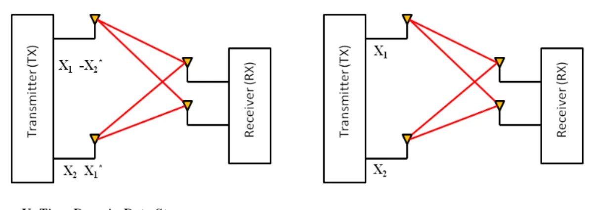
Space diversity uses redundancy to achieve transmitter diversity by sending or-thogonal information set at two different timeslots from two different antennas. It can also be implemented by combining multiple signals obtained through an array of receive antennas. These signals are transmitted from the same source but have passed through statistically independent channels. Fig. 3.5 illustrates the techniques of spa-tial diversity and spaspa-tial multiplexing for a MIMO system with two transmission and two reception antennas.
(a) Spatial Diversity (b) Spatial Multiplexing
Figure 3.5: Schematic Diagram of SD and SM for a 2x2 MIMO System
3.2.3 Beamforming
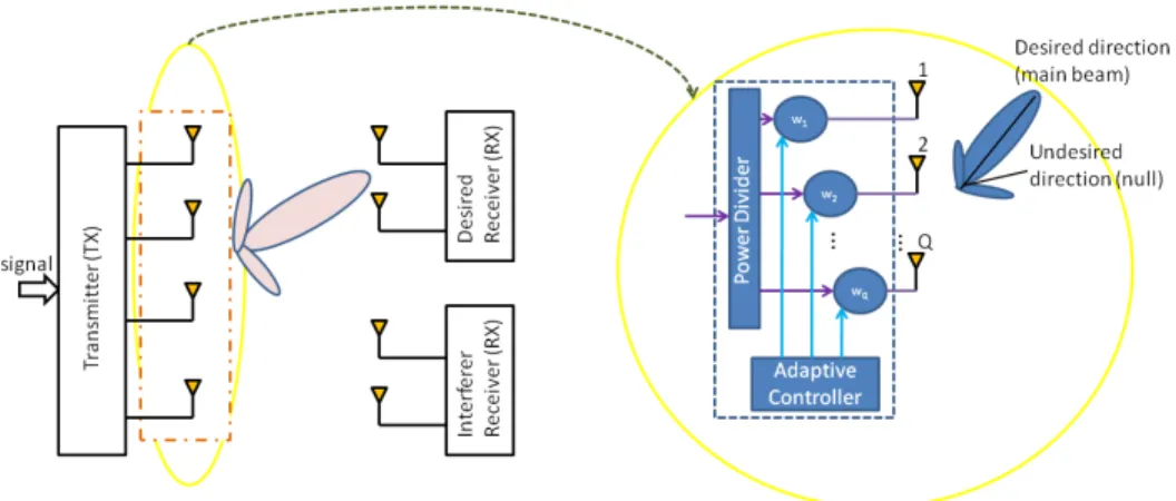
Beamforming or spatial filtering techniques uses the antenna array and advance signal processing algorithms to perform weighted processing on every physically sep-arated antenna in the array. Beamforming is intended to maximize the power of the desired signals while minimizing or nulling the power of the interfering signals by
controlling the relative magnitudes and phases of the signals. Fig. 3.6 demonstrates how the beamforming technique uses an array of antenna elements to steer a signal energy or beam in a desired direction. The adaptive controller at the transmitter exploits the CSI feedback to select different transmission weights for each antenna element. Note, the transmission powers for each element in the array can also be adaptively allocated.
Figure 3.6: Schematic Diagram of Beamforming using an Adaptive Antenna Array
3.2.4 Hybrid MIMO and Beamforming
In order to leverage the benefits of MIMO and beamforming: increased trans-mission rate and signal reliability or diversity gain – both technologies are often combined. In such a hybrid system the physical antenna elements in the array at the transmitter are sub-divided into sub-arrays. On each sub-array, one virtual antenna or beam is formed with beamforming. These beams constitute spatial diversity or spatial multiplexing as illustrated in Fig. 3.7.
(a) Spatial Diversity + Beamforming (b) Spatial Multiplexing + Beamforming
Figure 3.7: Schematic Diagram of a Hybrid MIMO and Beamforming System for four Transmission Antennas and two Reception Antennas
CHAPTER 4: SYSTEM MODEL: MIMO-OFDM FOR WIRELESS TRANSMISSION
The MIMO architectures and techniques discussed in Chapter 3 are developed for flat fading channels. However, many of the current and future wireless communication systems are broadband in nature, i.e., the communication is over a frequency selective channel. Consequently, OFDM, which turns the frequency selective channel into multiple parallel flat fading channels, has been adapted as a companion for MIMO processing in next generation technologies [59]–[62]. This combined application of multi-antenna technology and OFDM modulation, resulted in the creation of a new architecture called MIMO-OFDM. Currently, MIMO-OFDM has been selected to be the air interface of several standards, such as WiMAX [63], LTE [64], and LTE-Advanced [65]. In this Chapter, we will briefly describe the principle of OFDM transmission and then, present the basic idea behind MIMO-OFDM processing for multi-antenna communication systems.
4.1 Orthogonal Frequency Division Multiplexing (OFDM)
OFDM is a type of multicarrier (MC) modulation technique for signal transmission over wireless channels first proposed by Chang in [66]. It is essentially identical to the Discrete Multi-tone Modulation (DMT) technique and is a Frequency Division Multiplexing (FDM) scheme. These techniques divide the total available bandwidth in a communication medium into a series of non-overlapping frequency sub-bands known as subchannels or subcarriers, each of which is used to carry a separate signal. This allows a single transmission medium such as a cable or a radio link to be shared by many signals.
Unlike FDM, OFDM uses the spectrum much more efficiently by spacing the subchannels closer together (refer to Fig. 4.1); this is achieved by making all the carriers orthogonal. The orthogonality of the subcarriers means that each subcarrier has an integer number of cycles over a symbol period. Due to this, the spectrum of each subcarrier has a null at the center frequency of each of the other subcarriers in the system. This results in no interference between the subcarriers. “Each subcarrier in an OFDM system signal has a very narrow bandwidth (e.g., 1 KHz), thus resulting in low symbol rate. This results in the signal having a high tolerance to multipath delay spread, as the delay spread must be very long to cause significant InterSymbol Interference (ISI) (e.g., >500 µsecs) [53].”
Figure 4.1: Comparison of FDM versus OFDM
One of the primary advantages of OFDM over single-carrier schemes is its ability to cope with severe channel conditions that arise from frequency-selective fading due to multipath, interference and attenuation of high frequencies. OFDM simplifies
channel equalization by turning a frequency selective channel into a set of parallel flat fading channels, and thus, avoids the use of equalizers in Inter-Symbol Interference mitigation [67]. Some of the pros and cons of OFDM includes:
• High spectral efficiency;
• Provides an opportunity to use link adaptation [68];
• Provides efficient and low complexity equalization using Fast Fourier Transform (FFT) processing;
• Robustness for high-data rate transmission over multipath fading channel; • Sensitivity to synchronization errors – frequency offsets, timing errors and phase
noise;
• Relatively high peak-to-average power ratio, which reduces the power efficiency of the RF amplifier [70].
4.1.1 OFDM Transceiver
Fig. 4.2 shows a block diagram of the baseband processing of an OFDM transceiver for a Single Input Single Output (SISO) system. Once the binary input data is processed by a data scrambler, channel encoding is applied to improve the bit error rate performance. The output of the encoder is then interleaved to reduce the burst symbol error rate. The bit stream is then mapped into symbols using Multi-level Quadrature Amplitude Modulation (M-QAM) schemes such as 4-QAM, 16-QAM, and 64-QAM. Depending on the channel fading conditions, these modulation rates can be selected adaptively to boost the data rate. The resulting complex symbols or spectrum is then converted to its time domain signal using and IFFT. The IFFT provides a
simple way of ensuring the orthogonality of the subcarrier signals in addition to the efficient transformation of the signal to the time domain.
TEM MODEL: MIMO-OFDM F OR WIRELESS TRANSMISSION 37
After OFDM modulation, a guard interval is inserted to suppress the ISI caused by multipath distortion [53]. The guard interval is also known as theCyclic Prefix (CP). A cyclic prefix is a copy of the last part of the OFDM symbol, which is prepended to the transmitted symbol (refer to Fig. 4.3). This makes the transmitted symbol periodic, which plays a key role in identifying frames correctly. The addition of a guard interval allows time for the multipath signals from the previous symbol to die away before the information from the current symbol is received [71].
Figure 4.3: Cyclic Prefix Insertion
In addition to inserting a guard interval, OFDM also applies windowing - a tech-nique to reduce the out-of-band radiation when the OFDM symbol would have a “discontinuous” end or beginning. The raised cosine window or filter is normally applied for pulse-shaping in order to minimize ISI [72]. Fig. 4.4 illustrates the time domain spectrum of two OFDM symbols that are separated by a guard interval and can easily be filtered using windowing. After the cyclic prefix block, the digital signal is converted in the DAC (digital to Analog converter) to produce the analog baseband signal. It is then upconverted to RF, and then transmitted by the antennas over the wireless channel.
At the receiver side, the reverse operation of the transmitter is performed. First, the received RF signal is down-converted to baseband and subsequently converted from analog to digital using the Analog-to-Digital (ADC) converter. The receiver corrects the frequency offset and symbol timing by using the training sequence in-serted at the preamble by the transmitter. The CP is removed and then FFT is performed. The resulting signal is corrected for the channel influences, demapped, de-interleaved and finally decoded to obtain the transmitted binary output data.
Figure 4.4: Depicts how Guard Interval reduces ISI (Adapted from [73]).
4.2 MIMO-OFDM System
When an OFDM signal is transmitted through a number of antennas in order to achieve diversity or capacity (higher transmission rate), the system is known as a MIMO-OFDM communication system. This system leverages the aforementioned advantages of MIMO systems and of the OFDM transmission technique to combat the frequency-selectivity of wireless communication channels. As already discussed,
OFDM transforms a frequency-selective channel into parallel flat-fading subchannels, and the MIMO technology exploits the multipath propagation resulting from slow fading to improve system performance. Thus, in addition to the spatial and tem-poral dimension of MIMO, OFDM adds one extra dimension to exploit: frequency dimension. MIMO-OFDM architecture therefore, enables the application of the same MIMO techniques for both narrowband and broadband communications [59], [74].
Fig. 4.5 shows a unified MIMO-OFDM system with 2 transmit (TX) and 2 receive (RX) antennas. It combines the functionality illustrated in Fig. 3.3 with that in Fig. 4.2. However, a couple of new features were added to this unified system. In addition to the regular encoder, interleaver and mapper, a MIMO demultiplexer and multiplexer are added to both the transmitter and receiver side, respectively. The MIMO demultiplexer (MIMO Demux) separates the single signal input from the mapper into multiple output signals corresponding to the number of transmit antennas. The multiplexer (MIMO Mux block) does the reverse process of merging the parallel streams from the received antennas into a single output.
The signal substreams from the MIMO demultiplexer are subjected to OFDM modulation as already explained in the previous section. First, it is split into parallel IFFT input using the S/P block (Serial to Paralell) where the pilot tones for channel training are inserted; the cyclic prefix is also added to help combat ISI. The IFFT output is then merged into a serial stream and converted from digital to analog at the D/A block. The resulting baseband signal is upconverted to the radio frequency (RF) before being sent to the antenna controller. The antenna controller selects the best antenna states or configurations for transmission based on some feedback from the transmitter. The RF signal is then transmitted over the wireless channel where it experiences multipath and noise. On reception, the reverse process is carried out on the signal as illustrated in Fig. 4.5.
TEM MODEL: MIMO-OFDM F OR WIRELESS TRANSMISSION 41
CHAPTER 5: RECONFIGURABLE ANTENNAS FOR WIMAX/LTE
5.1 Introduction
With the emergence of high-speed data standards for wireless communications, the need for compact and efficient antenna systems for next generation communication technologies is on the rise. Tremendous progress has been made in the research of adaptive antenna systems such as reconfigurable antennas with numerous designs that are reconfigurable in frequency, pattern, polarization, or a combination of these parameters [20].
Pattern reconfigurable antennas are of special interest due to their ability to dy-namically change their radiation properties to the wireless channel characteristics. These antennas are able to generate uncorrelated radiation patterns which can pro-duce uncorrelated channel realizations in a multipath rich wireless channel for a given frequency [116]. As a result, “two co-located antennas with different patterns “see” differently weighted multi-path components so that they interfere differently resulting in better reception; this improves link reliability [10], and channel capacity [9].
In this part of the thesis work, we present two designs of pattern reconfigurable antennas for WiMAX application. We first present a characterization of each antenna solution and demonstrate through field measurements how the pattern reconfigura-bility of the antennas can be used to improve link reliareconfigura-bility.
Related Work
Several other approaches have been presented in [43] – [45]. In [43], a pattern reconfigurable microstrip parasitic array based on Yagi–Uda antenna radiation princi-ple, which uses four switches to reconfigure the radiation pattern into three variations,
![Figure 1.2: Standard MIMO System versus a MIMO System with Reconfigurable Antennas (Adapted from [8]).](https://thumb-us.123doks.com/thumbv2/123dok_us/9023140.2800174/22.918.231.752.132.638/figure-standard-mimo-versus-mimo-reconfigurable-antennas-adapted.webp)