Studies on design of spindle-tool system and
their effects on overall milling process
stability
Dissertation submitted to the
National Institute of Technology Rourkela
in partial fulfilment of the requirements
of the degree of
Doctor of Philosophy
in
Mechanical Engineering
by
Jakeer Hussain Shaik
(Roll Number: 512ME129)
under the supervision of
Prof. J Srinivas
January 2017
Department of Mechanical Engineering
i
Mechanical Engineering
National Institute of Technology Rourkela
January 11, 2017
Certificate of Examination
Roll Number: 512ME129 Name: Jakeer Hussain Shaik
Title of Dissertation: Studies on design of spindle-tool system and their effects on overall milling process stability
We the below signed, after checking the dissertation mentioned above and the official record book (s) of the student, hereby state our approval of the dissertation submitted in partial fulfilment of the requirements of the degree of Doctor of Philosophy in Mechanical Engineering at National Institute of Technology Rourkela. We are satisfied with the volume, quality, correctness, and originality of the work.
--- J Srinivas Principal Supervisor --- --- D.R.K.Parhi H.P.Roy Member (DSC) Member (DSC) --- --- H.B. Sahu Name Member (DSC) Examiner --- B.B. Biswal Chairman (DSC)
ii
Mechanical Engineering
National Institute of Technology Rourkela
Prof. /Dr. Jonnalagadda Srinivas
Associate Professor
January 11, 2017
Supervisor's Certificate
This is to certify that the work presented in this dissertation entitled '' Studies on design of
spindle-tool system and their effects on overall milling process stability'' by ''Mr. Jakeer
Hussain Shaik '', Roll Number 512ME129, is a record of original research carried out by
her under my supervision and guidance in partial fulfilment of the requirements of the degree of Doctor of Philosophy in Mechanical Engineering. Neither this dissertation nor any part of it has been submitted for any degree or diploma to any institute or university in India or abroad.
iii
This dissertation is dedicated to
My family members
&
iv
Declaration of Originality
I Jakeer Hussian Shaik, Roll Number 512ME129 hereby declare that this dissertation entitled “Studies on design of spindle-tool system and their effects on overall milling
process stability'' is my original work carried out as a doctoral student of NIT Rourkela
and, to the best of my knowledge, it contains no material previously published or written by another person, nor any material presented for the award of any other degree or diploma of NIT Rourkela or any other institution. Any contribution made to this research by others, with whom I have worked at NIT Rourkela or elsewhere, is explicitly acknowledged in the dissertation. Works of other authors cited in this dissertation have been duly acknowledged under the section ''Bibliography''. I have also submitted my original research records to the scrutiny committee for evaluation of my dissertation. I am fully aware that in case of any non-compliance detected in future, the Senate of NIT Rourkela may withdraw the degree awarded to me on the basis of the present dissertation.
January 11, 2017
Jakeer Hussain Shaikv
Acknowledgment
I would like to thank my supervisor Prof. J Srinivas for all his support, enthusiasm, guidance wealth of ideas, the time and effort he put for me in completing this work. I have selected the problem and known the developments in this area from time to time by constantly getting in touch with literature from him. I thank for his encouragement in making me to understand the complete details relating to manipulators.
I am thankful to our director Prof. Sunil Kumar Sarangi, and very much obliged to the Head of Department of Mechanical Engineering Prof. S.S. Mohapatra, NIT Rourkela for providing all the support and concern regarding my academic requirements.
I would like to thank to all my DSC members, Prof. B.B. Biswal, Prof. D.R.K. Parhi, Prof. H.P. Roy, and Prof. H.B. Sahu for their valuable suggestions and comments during this research work and other faculty members of the institute for their co-operation and help.
I would also like to thank my wife for her continued encouragement and support throughout the work. I am thankful to my daughter and son for bringing laughter and joy to my life. Finally, I would like to thank my father, mother and brother for their endless encouragement and motivation in completing this research work.
Specially, I extend my deep sense of indebtedness and gratefulness to all my colleagues M Rajasekhar, K.V Varalakshmi, Puneet Kumar, Prabhu L, M Rajasekhar Reddy, S Madhusmitha, N Khayyum, and many other M.Tech scholars who helped me to complete the project directly and indirectly. I am thankful to all the teaching & non-teaching staff of Mechanical Engineering Department for their kind cooperation.
January 11, 2017
Jakeer Hussain Shaik NIT Rourkela Roll Number: 512ME129vi
Abstract
High speed machining using vertical CNC milling centres continues to be a popular approach in a variety of industries including aerospace, automobile, mould and die casting etc. Chatter oscillations have significant influence in restricting the metal removal rates of the machining process. The cutting process instability or chatter is assessed by prediction of frequency response at the tool tip. Present work aims at evaluating the combined effect of a spindle-housing and tool holder on the dynamics of cutting tool by considering the flexibility of spindle unit supported on bearings. The spindle-tool is analysed by using finite element modeling using Timoshenko beam theory. The dynamic characteristics and tool-tip frequency responses are obtained without considering the cutting forces. The results are compared with receptance coupling approach and using 3D modeling in ANSYS. Further experimental modal analysis on the machining spindle of same dimensions has revealed the same dynamic modes. Using the validated FE model of the system, the effects of nonlinear bearing contact forces, spindle-tool holder interface stiffness, bearing span and axial preload, tool overhang and diameter on the frequency response and cutting process stability are studied. Optimal spindle-tool system is designed for achieving maximum dynamic stiffness.
The analytically stability lobe diagrams are obtained from the real and imaginary terms of these frequency responses at the tool tip. Dynamic stability issues in helical end-milling using the two and three dimensional cutting force models are considered for the analysis. The stability boundaries are experimentally verified using the cutting tests on both CNC milling spindle and modified drilling tool spindle systems while machining Al-alloy work pieces. Vibration and sound pressure levels are also employed to assure the stability of cutting operations, while surface images are used to identify the chatter marks at various combinations of cutting parameters. Dynamic milling model is employed with the flexible spindle-tool system by considering several effects including variable tool pitch, tool run-out, nonlinear feed forces and process damping. Design and stability studies on the modified drill spindle with a custom-designed work table for milling operations allowed in understanding several interesting facts about spindle-tool systems. Some control strategies including semi-active and active methods are implemented using finite element model of the spindle-tool system to minimize the chatter vibration levels/maximize the stable depth of cut during cutting operations.
Keywords: Frequency response; Spindle machine receptances; 3D stability model; variable pitch effect; run out effect; semi-active and active control strategies.
vii
Contents
Certificate of Examination i Supervisor's Certificate ii Dedication iii Declaration of Originality iv Acknowledgment v Abstract vi Contents viiList of Figures xii
List of Tables xviii
Nomenclature xix
Chapter 1 1
Introduction 1
1.1 Overview 1
1.2 Vibrations in machine tool 2
1.3 Stability issues in machining 4
1.4 Aim and objectives 5
1.5 Organization of the Thesis 6
Chapter 2 8
Literature Review 8
2.1 Bearing characteristics on the dynamic stability 8
viii
2.3 Cutting force modeling and stability issues 17
2.4 Milling process control issues 27
2.5 Summary 30
Chapter 3 31
Dynamic Modeling of spindle-tool unit 31
3.1 Analytical modeling of spindle system 32
3.1.1 Modeling of spindle shaft 32
3.1.2 Bearing system 34
3.2 Coupled spindle tool system 36
3.2.1 Distributed parameter modeling 37
3.2.2 Finite element modeling 38
3.2.3 Effect of joint stiffness in spindle-holder-tool assemblies 40
3.2.4 Modified Receptance coupling theory 41
3.3 Numerical Results 49
3.3.1 Frequency response studies 50
3.3.1.a Full-order finite element modeling approach 50
3.3.1.b Receptance coupling sub-substructuring 51
3.3.1.c Three-dimensional finite element modelling 55
3.3.1.d Experimental Modal Analysis 58
3.3.1.e Studies on spindle-tool system interfaces with interface stiffness 60
3.3.1.f Non-linear bearing force effects 64
ix
3.3.2.a Optimum Design of Experiments 73
3.3.3 Optimal design of spindle-tool system 79
3.3.4 Dynamic modelling of drilling-spindle for milling-A case study 91
3.4 Concluding remarks 98
Chapter 4 100
Cutting dynamics and stability analysis 100
4.1 Classical cutting force model 101
4.1.1 Effects of process damping 112
4.1.2 Cutting force simulation with tool run-out 118
4.1.3 Cutting force simulation with variable pitch effect 120
4.2 Three-dimensional cutting force model 123
4.2.1 Time-domain simulations 131
4.2.2 Nonlinear force feed model 135
4.3 Effects of spindle-tool system parameters on stability 138
4.4 Cutting dynamics with nonlinear bearing forces 140
4.5 Stability analysis of a practical drill spindle for milling 143
4.5.1 Sound spectrum analysis using LabVIEW 146
4.5.2 Stability charts for modified drill spindle 151
4.6 Conclusions 152
Chapter 5 154
Control strategies in end milling process 154
x
5.2 Semi-active control using secondary system 156
5.3 Active vibration control 163
5.4 Conclusions 170 Chapter 6 171 Conclusions 171 6.1 Summary 171 6.2 Future Scope 173 References 174
APPENDIX -A Finite element matrices 187
A.1 Shape functions 187
APPENDIX-B Fourth order Runge-Kutta time integration method 192
APPENDIX-C Static condensation techniques 193
APPENDIX -D Training algorithm for MLP neural network 195
D.1 Neuron model 195
D.2 Learning in Multi-Layer Perceptron 196
APPENDIX -E LabVIEW programs for sound spectrum analysis 197
E.1 Read the sound spectrum data 197
E.2 Save the sound spectrum data 197
E.3 Power spectral density of cutting signals 198
APPENDIX-F Computer programs 199
F.1 Finite element method to obtain the matrices 199
xi
F.3 Programs for Stability Computations 201
F.4 Programs for time domain computations 202
F.5 Programs FFT and amplitude spectrum 203
F.6 Programs for process damping 204
Dissemination 205
xii
List of Figures
Figure no. Caption Page no.
2.1 Jones’ elastic model of the bearing 10
2.2 Schematic view of the integrated spindle-tool unit 14
2.3 Geometry of a helical end mill 19
2.4 Tool deflection due to milling forces 21
2.5 Variable pitch angle of the helical end mill 23
2.6 Geometry of milling tool with damper 28
3.1 Integrated spindle tool unit 31
3.2 Section of the beam 33
3.3 Ball bearing schematic 35
3.4 Simplified spindle-tool unit 37
3.5 Equivalent model of spindle-tool device 40
3.6 Equivalent line model of spindle tool unit 41
3.7 Overall process chart 42
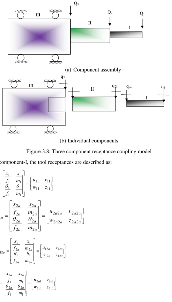
3.8 Three component receptance coupling model 43
3.9 Finite element model of spindle supported by housing 48
3.10 Tool tip frequency responses using the Full-order FEM 51
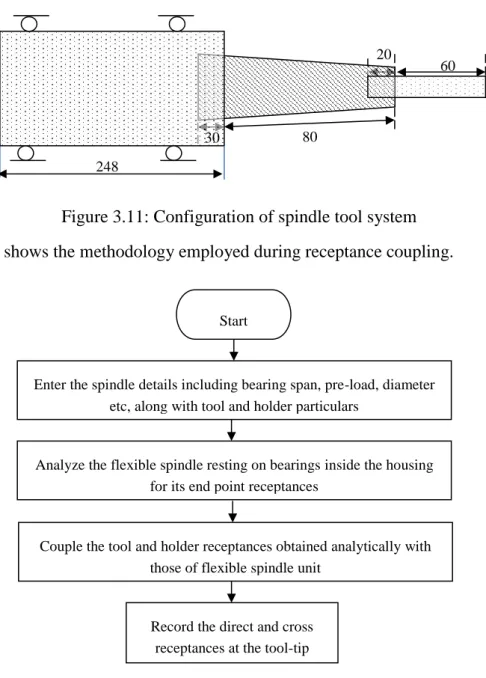
3.11 Configuration of spindle tool system 52
3.12 Present receptance coupling concept 52
xiii
3.14 Spindle machine receptances (Y3b3b) obtained from finite element
analysis
54
3.15 Tool tip frequency response of the assembly 55
3.16 Individual solid work components of MTAB MAXMILL realistic
spindle system
56
3.17 Meshed model of spindle-bearing system 56
3.18 First six mode shapes of spindle tool unit 57
3.19 Harmonic response of spindle bearing system 58
3.20 First modal frequency of spindle-tool assembly 58
3.21 Experimental set up employed 59
3.22 Frequency response of the integral tool-spindle unit 60
3.23 Equivalent model of the spindle-tool interfaces with distributed
contact springs
61
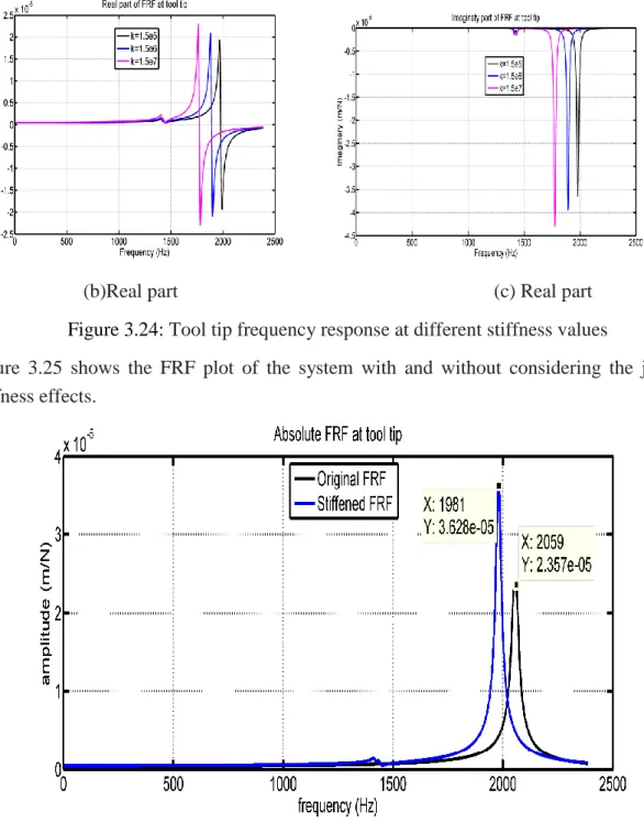
3.24 Tool tip frequency response at different stiffness values 62
3.25 Tool tip FRF with rigid and flexible interfaces 62
3.26 Tool tip FRF plots for different structural damping factors 63
3.27 Element degrees of freedom for spindle discretization 64
3.28 Tool-tip node displacements at r0=10m 65
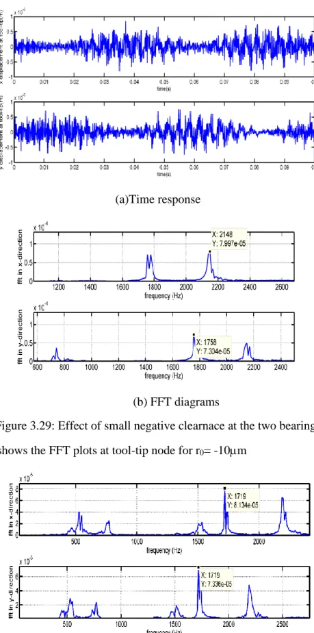
3.29 Effect of small negative clearance at the two bearings 66
3.30 FFT plots for negative radial clearance of-10m 66
3.31 FFT plots for different preload values (r0=10m) 68
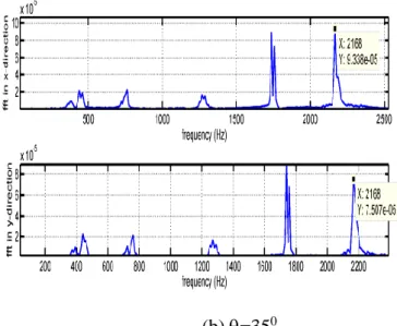
3.32 FFT at tool-tip node in two lateral directions 69
3.33 Effect of bearing span on spindle-tool dynamics 70
xiv
3.35 Effect of bearing preload on spindle-tool dynamics 72
3.36 Variation of fundamental frequency with other parameters 73
3.37 Data normality testing for natural frequency 76
3.38 Signal to noise ratios plots for the control factors on natural
frequency (Hz)
76
3.39 Data normality testing for dynamic stiffness 78
3.40 S/N plots for control factors on dynamic stiffness 78
3.41 Imaginary part of FRF of spindle 80
3.42 Block diagram of the proposed Neuro-Genetic system 80
3.43 Typical 3-layer neural network 81
3.44 Neural network model in present case 82
3.45 Convergence trends for various hidden neuron structures 83
3.46 Correlation between the predicted values and test data 84
3.47 Error plot rate of HS algorithm 87
3.48 Flowchart for genetic algorithm 89
3.49 Error plot rate of GA algorithm 89
3.50 Tool-tip FRF for the spindle-tool unit with optimal dimensions 91
3.51 Drill-spindle modification procedure 88
3.52 Original component modeling of drilling spindle 92
3.53 Spindle-tool unit of the in-house drilling machine 93
3.54 Instrumentation for modal analysis 93
3.55 Experimental response for original drill spindle 95
xv
3.57 Tool tip FRF of drill and modified spindle 97
3.58 Meshed assembly of the model in ANSYS Workbench 97
3.59 Comparison chart for the first mode of vibration 98
4.1 Two-degree of freedom milling model 101
4.2 Stability lobe plots for different percentages of radial immersion 107
4.3 Experimental set-up employed 108
4.4 Machining areas of workpiece at different depths of cut 109
4.5 Time history and FFT plots for different axial depths of cut 110
4.6 Amplitude and FFT plots for different axial depths of cut 111
4.7 Predicted SLD with experimental validation 111
4.8 Geometry for up-milling using average tooth angle approach 113
4.9 Geometry for down-milling using average tooth angle approach 114
4.10 Analytical stability lobe diagrams 116
4.11 Cutting tool vibrations at 3000rpmat 1mm depth of cut 117
4.12 Tool displacement levels with run-out correction 119
4.13 Force variations with tooth-to-tooth run-out 120
4.14 Angular position of edges for end mill on cutter circumference 121
4.15 Time domain simulation with variable pitch at 25% radial
immersion
122
4.16 Tool vibration levels at 1mm depth of cut 122
4.17 Three-degree of freedom cutting force model 123
4.18 Stability lobe diagrams with 40%depth of immersion 128
xvi
4.20 Experimental response and FFT plots at differnt axial depths of
cut
130
4.21 Optical microscope images of workpiece 131
4.22 Predicted SLD with experimetal validation 131
4.23 Three directional cutting force histories 132
4.24 Time history plots for an axial depth of cut of 1mm 133
4.25 Time history plots for an axial depth of cut of 2 mm 134
4.26 Phase plane plots at 1850 rpm 135
4.27 Time domain simulation at a depth of 4mm 135
4.28 Effect of non-linear feed rate forces 137
4.29 Prediction of average stable depth of cut 138
4.30 Variation of average depth of cut as a function of spindle tool
parameters
140
4.31 Stability lobe diagram at the critical bearing span=180mm 140
4.32 Transient response with bearing and cutting forces 141
4.33 Experimental set-up employed 142
4.34 Experimental FFT plot 143
4.35 Experimental set-up employed for the modified drilling machine 144
4.36 Time histories and FFT plots at 1030 rpm 145
4.37 Time histories and FFT plots at 1300 rpm 145
4.38 Time history and FFT plots at 1650 rpm 146
4.39 Amplitude and FFT plots for different depths of cut at 1030 rpm 148
xvii
4.41 Amplitude and FFT plots for different depths of cut at 1650 rpm 150
4.42 Testing of stability boundaries with surface images 151
4.43 Stability lobe diagrams for modified spindle 152
5.1 Classification of the methods for chatter mitigation 156
5.2 Finite element discretization of spindle-tool system with vibration
absorber
157
5.3 Tool tip FRF of the spindle-tool unit 159
5.4 Stability lobe plots with and without absorber 159
5.5 Flowchart of PSO algorithm 161
5.6 Convergence trend corresponding to population size=30 162
5.7 Tool tip FRF with optimal vibration absorber parameters 162
5.8 Stability lobe diagrams from tool-tip FRF 163
5.9 Block diagram of a single-input single-output system closed loop
system
164
5.10 Block diagram of control scheme 165
5.11 Electro-magnetic actuator for the spindle 166
5.12 Tool tip vibration levels at a depth of 1mm 167
5.13 Tool tip vibration levels at a depth of 3mm 168
5.14 Time domain simulation at a depth of 1mm and 3mm 169
xviii
List of Tables
Table no.
Caption Page no.
3.1 Parameters of the finite element model 50
3.2 Convergence result of natural frequencies of spindle tool unit 51
3.3 Parameters of the tool-holder and spindle machine unit 51
3.4 Detailed simulated experimental data using Taguchi L27 (3**5) array 70
3.5 Analysis of Variance for natural frequency (Hz) 71
3.6 Response table for signal to noise ratio (Larger is better) 73
3.7 Analysis of Variance for dynamic stiffness (N/m) 74
3.8 Response table for signal to noise ratio (Larger is better) 75
3.9 The weight structure for 5 hidden node skeleton 80
3.10 Optimal data from HSO and GA 86
3.11 Modal frequencies (Hz) 94
4.1 Modal and cutting coefficients for the system 102
4.2 Summary of directional orientation factors 110
xix
Nomenclature
j Angular location of the jth ball β Helix angle, Learning rate
γ Non-linear feed power constant
j Radial deformation of the jth ball
Solid damping factor
Run cut angle
ρ Run-out of cutting edge
Tooth period
j Instantaneous angular immersion of the tooth (j)
Ω Angular spindle speed (rad/s)
p Tooth pitch
Θ Contact angle of static angular-contact ball bearing
ωc Chatter frequency
µx and µy Directional orientation factors in x and y directions *
t
N Average number of teeth in the cut,
) ( j
h
Instantaneous variable total chip thickness
j ro
h Variation of the chip thickness due to run-out
[A(t)] Directional coefficient matrix in time domain
[A0] Immersion dependent directional cutting coefficient matrix
[H(iωc)] Frequency response function at tool tip in frequency domain
{F} Force vector
b Axial depth of cut
blim Average stable depth of cut obtained from the stability lobe
C Process damping coefficient
xx
Cb Interface stiffness of balls and radii of curvature
cnew, x, cnew, y Damping for the process stability calculations
Db Ball diameter
E Elastic modulus
Es Material dependent damping
Fa Bearing preload
Fd Process damping force
ft Feed per revolution
Ft,k, Fr,k, Fa,k Tangential radial and axial force components
ft,mean Mean feed per tooth
H (.) Heavy-side function
Hor Oriented frequency response function
k1, k2 Absorber stiffness coefficients in two directions
KP, KD Parameters of the proportional and derivative gains
Kt, Kr, Ka Tangential, radial and axial cutting coefficients
kxx, kyy Static radial stiffness of the bearings
Kxx, Kyy, Kzz Cutting stiffness coefficients in X, Y and Z directions
m1 ,m2 Masses of the damper in two directions
N Number of teeth of the cutter
n Spindle speed in rev/min calculated through tooth passing period
Nb Number of balls
nj-1 , nj Present and previous tooth periods
r, R Radii of inner race and outer race
r0 Radial clearance
U(t) Control force
zloc Location of the absorber placement
1
Chapter-1
Introduction
1.1 Overview
Modern industries focus on high quality machining and automation technology. Quality of products and productivity are improved by continuous monitoring of machine tools and process. The competitive economic environment has brought new challenges to the machining industry. Significantly reductions in machining time, production cost, and improvement in overall productivity have become an ultimate requirement. Especially, in machining industries, the main objective is to select chatter free cutting conditions with lower cutting forces while maintaining the power and torque limits of machine tools and other practical constraints of the system. Therefore, right and optimal selection of cutting conditions is of great concern for machining industry. In order to satisfy the needs, a system must be developed to ensure the optimal selection of cutting conditions as well as the design of spindle-tool system with various physical phenomena occurring during machining.
The condition monitoring strategies have importance in assessing the quality of the machining process for improving the overall efficiency of the system. Cutting forces, workpiece surface quality, tool vibration levels, sound pressure intensities are some of the important process indicators which determine the limits on the cutting conditions, accuracy of products, machine tool failures and other information useful for monitoring and controlling the machining process. It is well known that productivity reduces due to onset of regenerative chatter phenomenon associated with instabilities in cutting operations.
In machining operations like milling and boring, regenerative chatter instabilities hamper the machining continuity and such conditions need to be identified at the beginning itself. Out of various factors, spindle design is one of the important issues dictating the process stability. For example, a rigid spindle permits higher depths of cuts without violent oscillations during machining. However, spindle works in combination with tool and holder system, whose flexibility plays an important role in cutting operations.
Chapter-1 Introduction
2
1.2 Vibrations in machine-tool
Vibration analysis in metal cutting has significance since vibrations may cause loss of surface finish of work pieces, shortens tool life, degrades machine tool components and produces noise contamination. In addition, the mechanics of the cutting process is also affected by the vibrations, changing the contact conditions between the tool and the material. During the machining processes, three different types of mechanical vibrations can occur due to the lack of dynamic stiffness of one or several elements of the system composed by the machine tool, tool holder, cutting tool and the workpiece material [1]. These are (i) Free or transient vibrations (ii) Forced vibrations and (iii) Self-excited vibrations. In the first case, the vibrations are initiated by an external energy source momentarily and thereafter removed. In the absence of non-conservative forces, free vibrations sustain themselves and are periodic. The structure will vibrate in its natural modes until the damping causes the motion to die out. Forced vibrations occur due to external harmonic excitations. The principle source of forced vibrations in milling processes is when the cutting edge enters and exits the workpiece. However, forced vibrations are also associated with unbalanced bearings or cutting tools, or it can be transmitted by other machine tools through the workshop floor. Self-excited vibrations also known as chatter, extract the energy to start and grow continuously, as a result of the interaction between the cutting tool and the workpiece during the machining process. Such a chatter phenomenon is further classified into regenerative and non-regenerative types. The regenerative effect is caused by the undulation of successive cuts, where the tool removes a wavy surface generated in the previous pass. Non regenerative vibration is maintained by the cutting force fluctuations that are induced by the tool-workpiece relative displacement of a periodic nature.
Free and forced vibrations can be avoided or reduced if the causes of the vibration are identified. In this field, a variety of methods and techniques have been developed to mitigate their occurrence. However, self-excited vibrations as a result of an unstable interaction between the machining forces and the structural deflections cannot be avoided .The forces generated when the cutting tool and part come into contact produce significant structural deflections. These structural deflections modulate the chip thickness that, in turn, changes the machining forces. Regenerative chatter may result in excessive machining forces and tool wear, tool failure, and unacceptable surface finish, thus severely decreasing operation productivity and part quality, loss of contact and mode coupling effects. When chatter occurs, the vibration amplitude will increase continuously until the relative displacement between the cutter and workpiece is so large that the cutter will leave the workpiece for part of the time. This becomes a nonlinear behavior, which limits the vibration amplitude to a finite value. The magnitude of vibration depends on the cutting
Chapter-1 Introduction
3
force characteristics, such as the magnitude and direction of the cutting forces, and the tooth passing frequency at which a cutting flute comes in contact with the workpiece. The dynamic characteristics of the entire machining system in terms of the natural frequencies the damping coefficients and the stiffness of the machine tool structure, also affect the vibration magnitudes.
In comparison with other machining processes, the cutting force characteristics of milling process are more complex (see for e.g., [2]). The cutting forces generated during a milling process induce dynamic deflections of the workpiece-tool system, which in turn modulate the cutting forces. Such self-excited vibrations are mostly caused by two well-known mechanisms: regeneration and mode-coupling. As described earlier paragraphs, regeneration occurs when the cut produced at a current time leaves a wavy surface on the material regenerated during subsequent passes of cut. The phase difference between the inner and outer waves and the amplitude gain of the system plays a key role in stability of cutting process. In mode-coupling approach, even when there is no interaction between the undulated surface of workpiece and tool vibration, the tool traces out an elliptic path that varies the depth of cut in such a way to intensify the coupled modes of vibration. Self-excited vibrations may persist in machining operations and require attention.
In traditional low-speed machining processes, the machining dynamics are not considered as a significant issue because spindle speeds and depths of cut are conservatively selected. Therefore, the system vibrations are typically small. However, with the increased use of high-speed machining and requirements for smaller parts with higher tolerances, errors caused by machining dynamics can be significant. The behavior of a dynamic system depends on the force input and its dynamic characteristics. In operations like milling, the force depends on a combination of user defined parameters and the interaction between the tool and the workpiece. Some user defined machining parameters include: the axial depth of cut, the radial depth of cut, the feed rate, and the spindle speed. In addition to this, selection of the cutting tool affects the machining accuracy due to material composition, tool geometry, and coatings all influence the forces that are developed between the tool and workpiece.
In any dynamic system, the time dependent motion, or vibration, is determined by the system’s dynamic response and the force input and initial conditions. Especially, in milling, the system dynamics includes that of combined machine-tool-holder-workpiece system model. The system dynamics are generally expressed as the complex valued ratio of the displacement to the input force over a selected frequency range; called frequency response function (FRF) and it can be modeled or measured. The FRF is determined at the point of interest for example at the free end of the cutting tool, which usually represents the most flexible point in the system connecting the tool and workpiece.
Chapter-1 Introduction
4
1.3 Stability issues in machining
Machining systems involve a machine tool, a cutting tool and holder, and a workpiece and work holding devices as structural elements. Depending on their relative rigidity, one or more components may dominate the total deformation at the tool-workpiece contact point contributing to the form errors and the dynamics of the process which may yield instability. Generally, machining centres are composed of a bed, linear and rotary axes, a column, a spindle etc., the spindle-holder-tool assembly is usually the most flexible part of the whole system due to the slender geometries of these components and multiple interfaces between them. In this case, the cutting process forces are the main cause of the structural deformations.
In machining process, stability depends on the phasing of vibrations on each successive flute engagement. As the cutter engages with the workpiece, forces are generated which cause vibrations. These vibrations, in turn, are imprinted on the workpiece surface. If the vibrations are in phase with (i.e., match up to) the surface left by the previous tooth engagement, then the chip thickness remains relatively the same. When the vibrations satisfy this “in phase” condition, the forces and vibrations in the system persist in a steady state or stable condition. On the other hand, if the vibrations from one tooth engagement to the next do not match up or are “out of phase”, the chip thickness varies and the force amplitude varies. The force variation excites the system dynamics and causes vibrations which lead to subsequent changes in the chip thickness. This system is described by using a set of time delayed differential equations (one for each force direction in consideration) where the time between tooth engagements is the amount of the delay. The phase difference between engagements depends on the spindle speed and axial depth of cut acts as the feedback system gain. Stability information can be presented in terms of input parameters (axial depth, spindle speed and radial depth). Generally at a particular radial depth, a stability lobe boundary is predicted in the spindle speed-axial depth domain.
The stability lobes diagram is a plot that separates stable and unstable machining operations for different spindle speeds. Stable cuts occur in the region below the stability boundary, while unstable cuts (chatter) occur above the stability boundary. The user can select optimum operating conditions for spindle speed and axial depth of cut based on this diagram. Stability lobes are functions of the dynamic stiffness at the tool center point (TCP), the tool geometry, the radial immersion of tool into material, as well as of the material to be machined. Machining operators usually, distinguish between two types of chatter (i) structural chatter or machine chatter: which is low frequency chatter, recognizable for a low-pitched sound and the chatter is associated with the structural modes of the machine. (ii) tool chatter: which appears at higher frequencies and is recognizable
Chapter-1 Introduction
5
for a high-pitched sound, the chatter is associated with the modes of the tool or spindle. The type of chatter depends on the cutting frequencies; low cutting frequencies excite structural modes and high cutting frequencies excite spindle- tool holder-tool modes. The mechanical modeling of the spindle-tool system is a key to estimate the static and dynamic behavior of a machine tool. An accurate modeling of this system is very important part in predicting stability of cutting process. Detailed description of chatter stability can be found in open literature (e.g., [3]).
1.4 Aim and objectives
From the last two decades, chatter phenomenon has been extensively studied to predict the appropriate machining conditions. In parallel, different methods to counteract tool chatter have been developed and are being used in the machining industries. The operations such as milling may require a special attention even at normal operating conditions with flexible/rigid tool work combinations. In applications such as utilizing a drilling machine for milling operations, the spindle design modifications are very important to machine the components smoothly.
The main focus of present work is to design the spindle-tool unit by considering various factors affecting the tool-tip frequency response along with stability studies during cutting with the use of optimally designed spindle-tool system.
The combined dynamics of a spindle-tool unit on the process effectiveness is to be presented by considering the flexibility of spindle unit supported on bearings. Frequency response functions at the tool-tip are to be obtained for the spindle-tool
model using various approaches such as direct finite element method, receptance coupling approach and experimental modal analysis.
Optimal spindle-tool system parameters are to be obtained for achieving the maximum dynamic stiffness and improving the cutting process stability.
Cutting process stability is to be validated with the designed spindle by considering the practical conditions with the help of time-domain and frequency-domain (stability lobe diagrams).
Case studies are to be conducted by modifying the design of drill spindle to improve the cutting stability while it is used for slot cutting operations as in a three axes milling machine.
Detailed experimental cutting tests are to be conducted for stability testing by measurement of vibration levels, sound pressure intensities and surface images using the designed spindles.
Chapter-1 Introduction
6
In improving the stability boundaries, some semi-active and active control strategies are to be implemented without changing the major operating variables significantly.
To develop semi and active control methods for maximizing the stable depth of cut and reduction of chatter in online fashion.
Some of the contributions in the present work are as follows:
(i) Development of a generalized approach for dynamic model for the spindle-tool unit by accounting practical considerations including joint interface effects, non-linear bearing forces etc.
(ii) Optimal design of spindle-tool unit for maximizing the dynamic stiffness and improving the average stable depth of cut
(iii) Design and modifications of drill spindle for milling operations.
(iv) Improvise the stability limits by using semi-active and active control techniques. Various experimental and numerical studies support the concepts provided in the work.
1.5 Organization of the thesis
Thesis is organized into six chapters. In the present chapter, the spindle-tool system and its importance in assessment of machining stability has been introduced.
Chapter-2 deals with the comprehensive literature review related to the current work. The various works related to design analysis and control of spindle-tool systems as well as their influence on machining process performance are reported.
Chapter-3 presents the results of theoretical modeling such as finite element analysis using Timoshenko beam theory. Further one of most popular coupling techniques such as receptance-coupling substructure analysis (RCSA) are highlighted in this section. Three dimensional analyses are conducted on the prototype spindle-tool unit in ANSYS Workbench. Later parametric studies are carried for the spindle and tool design variables. Since one of the purposes of modeling the spindle system is to avoid chatter vibrations during machining process, the maximum dynamic stiffness has to be improved. Meta-heuristic optimization studies are presented in order to show the importance of these techniques in the effective design of spindle-tool unit. Further, a modified design approach for drilling spindles is illustrated economically for milling operations.
Chapter-4 describes the role of the dynamic interaction between the spindle system and the work piece on the overall performances and presents the generalized dynamics of 3-axis milling operations. The chatter stability of the milling operations are solved both in
Chapter-1 Introduction
7
frequency and time domains. A detailed comparison of various stability models is also presented. Moreover, the analytical zero-order solution available in literature is generalized to model stability of end mills with complex geometries. Time domain simulations are carried out for different cases of process parameters that affect the cutting force dynamics. Chapter-5 deals with the study of active structural methods dedicated to the suppression of chatter. A block diagram of the control system is developed. The frequency-response characteristics are determined from mathematical modeling for the closed-loop vibration control system is presented.
Moreover, chapter-6 summarize the major findings from the research and make the recommendations for the future research.
8
Chapter-2
Literature review
Enormous literature is available on various issues relating to milling operation. Especially, for predicting the role of spindle during the milling operation in-terms of stability, and subsequent effects including work piece surface finish and tool wear, several research articles appeared over last one decade. Literature in the present work is classified under the following headings.
2.1 Bearing characteristics on the dynamic stability
The spindle-bearing system is one of the most critical components of the high speed spindles, must able to provide high rotational speed and reasonable load capacity. The types of bearings that are available for high speed spindles are angular-contact ball bearings, roller bearings and taper roller bearings. Angular contact ball bearings are most commonly used today in high-speed spindles. This is because angular contact ball bearings can provide the required precision, load carrying capacity, and spindle speeds. In addition, the costs are low compared to hydrostatic, aerostatic or magnetic bearings.
Angular contact ball bearings are designed to provide the capabilities to withstand external loads from both axial and radial directions when they are properly preloaded. In some cases, taper roller bearings are also used because they can offer larger load-carrying capacity and higher stiffness than ball bearings. However, taper roller bearings do not allow the high speeds required by high speed spindles. In this thesis, angular contact ball bearings are studied.
The dynamics of spindle systems mainly depends on the characteristics of the bearings, tool-holder interface, spindle shaft and housing. This review gives an overview of previous research findings of the spindle design analysis and their effects of the cutting dynamics. The simplest model for angular contact ball bearings is the conventional two-degrees-of-freedom proposed by Palmgren [4]. This model considers only the axial and radial translations of the inner ring relative to the outer ring, which is usually suitable for most applications where misalignment and shaft bending effects are insignificant. The pioneering work on mathematical models for angular contact ball bearings was proposed by Jones [5], who developed a general theory for load-deflection analysis of bearings that considered centrifugal force and gyroscopic loading of the rolling elements under high-speed operation.
Chapter-2 Literature review
9
Demul et al. [6] established the dynamic equations in a matrix form that considered the centrifugal force but neglected the gyroscopic moment in the bearing. This method provides an advantage that the Jacobian matrix of the bearing is derived analytically, producing the bearing stiffness. Filiz and Gorur [7] conducted a load-deflection analysis of bearings under combined axial and radial loads. This analysis produced a simplified model for determining the incremental stiffness in axial and radial directions.
Houpert [8] and Hernot et al. [9] presented a stiffness matrix form with five degrees of freedom. Their model enables using the finite element method for solving the coupled problem of the spindle-bearing system, but the centrifugal forces and gyroscopic moments are not included. Harris [10] conducted a comprehensive analysis of different aspects of bearings, but his model is independent of the spindle and shaft.
Walford and Stone [11-12] measured stiffness and damping for bearings under oscillating conditions. They used two degrees of freedom mathematical model to extract a representative stiffness value and found that the levels of damping obtained were considerably higher than expected. They concluded that this result was due to interaction among the races, housing and shaft.
Tiwari and Vyas [13] developed a technique for estimating nonlinear stiffness parameters for rolling in rotor systems, based on an analysis of the random response signals picked up from the bearing caps. The analysis uses a stochastic characteristic of the bearing excitation in conjunction with a single degree of freedom model to estimate a representative stiffness. Marsh and Yantek [14] presented an experimental method for estimating the dynamic stiffness of precision bearings, based on measurements of the frequency response functions.
Aini et al. [15] carried out experiments to investigate the frequency responses of grinding machine tool spindle supported by angular contact ball bearings. Several works [16-19] proposed the fundamental theory of bearings for the high speed spindles and proposed the recent trends in design of spindles. The main lubrication systems for bearings are grease and oil air lubrication. The advantage of grease lubrication is that the rotation speed can be quite high without high cost and maintenance.
However, for advanced high speed spindles, the oil air lubrication system is required because of its low viscosity and exhaust system [20-21]. The preload for the bearings is also an important issue for high speed spindles. The preload tends to increase with the increase of the rotation speed of the spindle, and the over preload causes the bearings to break. Therefore, the preload must be applied and adjusted properly, with a suitable preload system depending on the spindle specifications. Angular contact ball bearings have been widely used in machine tool spindles, and the bearing preload plays an
Chapter-2 Literature review
10
important role on the performance of the spindle. With the development of high speed machining, especially for high speed milling, heavy cutting at a low speed and light cutting at a high speed are often performed on a single machine tool spindle, thus, high stiffness at low speed and low temperature rise at high speed are required.
Lin et al. [22] presented an integrated model with experimental validation and sensitivity analysis for studying various thermo-mechanical-dynamic spindle behaviours at high speeds. The bearing preload effects on bearing stiffness, high-speed rotational effects, including centrifugal forces and gyroscopic moments on the spindle shaft and, subsequently, on overall spindle dynamics are investigated.
Jiang and Mao [23] investigated the variable preload technology was systematically applied to the high-speed spindles. At high-speed range, FEM method was used to analyze the temperature distribution of the spindle, and the variable spindle preload was determined according to the constraint of temperature rise of bearings.
Ozturk et al. [24] predicted the spindle speed-dependent dynamic properties at the tool tip and errors in-process stability predictions. Effects of bearing preload on the stability limits were demonstrated via simulations and cutting tests. Cao et al. [25] compared two main types of bearing preloads such as constant and rigid mechanisms using a mathematical model as well as with experiments. Timoshenko beam element theory coupled with a non-linear model of angular contact ball bearings, the dynamics of the spindle shaft, housing, and bearings system was modelled as a non-linear function of preload mechanism and amplitude, spindle speed, and external cutting loads. Figure. 2.1 shows the bearing model employed in this work.
Figure 2.1: Jones’ elastic model of the bearing [25]
Kim et al. [26] developed statistical models and software’s to numerically simulate the rotational precision of spindles running on ball bearings. It was identified that the rotational accuracy of the spindle can differ significantly with spinning speed. The impact of the bearing preload has an extra significance.
Chapter-2 Literature review
11
Zahedi and Movahhedy [27] extended a widespread model of high speed spindles that includes viable models for the mechanical and thermal behaviour of its major components such as bearings, shaft and housing. The spindle housing and shaft were treated as six-degree-of-freedom Timoshenko beam elements.
Zivkovic et al. [28] presented the thermo-mechanical model of the spindle with angular contact ball bearings. The non-linear change of spindle stiffness under the influence of temperature is studied and it is experimentally verified.
2.2 Spindle design and optimization issues
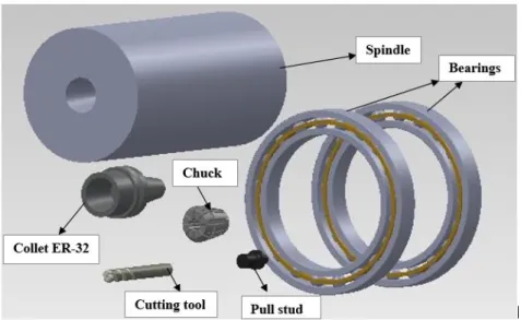
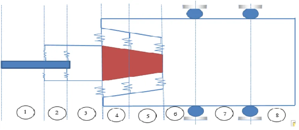
A schematic of the spindle-drawbar-bearing assembly of a high-speed milling motorized spindle unit is shown in Figure 2.1. The rotor of the spindle is supported by two pairs of angular contact ball bearings. To drive this spindle bearing system, an integral induction motor is located between the front and rear bearings. A drawbar is mounted inside the hollow shaft to change tools. The hollow shaft, the drawbar and the bearings constitute a typical double-rotor dynamic system. Labels (1, 5) represents the front and rear bearings and (2, 3, 4) represents the spindle, motor rotor and drawbar.
In an effort to choose the factors that avoid chatter and to attain the better surface finish, accurate dynamic models of tool-holder-spindle assembly are required. Such a dynamics reflected at tool tip can be acquired by modal testing, but entails a huge number of tool-holder arrangements in a manufacturing facility. The measurements are time taking and at times, problematic as in the case of micro-end mills. Few studies are reported in view of analytical and experimental works related to modelling of the spindle.
Yang [29] conducted an in-depth analysis of the radial stiffness of machine-tool spindles. He concluded that shortening the overhang, and increasing the area moment of inertia of the spindle and the stiffness of the front bearing, can enhance the static stiffness of spindle systems. The addition of the third bearing may change the dynamics of the spindle, depending on the forces and moments exerted on it.
Ruhl and Booker [30] is one of the earliest researchers to use the finite element method for modelling of rotor systems. His model includes translational inertia and bending stiffness but neglects rotational inertia, gyroscopic moments, shear deformation, and axial load. Nelson [31-32] used the Timoshenko beam theory to establish shape functions and formulate system matrices, including the effects of rotary inertia, gyroscopic moments, shear deformation, and axial load.
Jorgensen and Shin [33] used DeMul's bearing model and the Timoshenko beam to develop a model for a spindle supported by a pair of angular contact bearings, including cutting-load effects. The cutting load is divided into static and dynamic components. The
Chapter-2 Literature review
12
dynamic loads are assumed to provide system excitation due to the dynamic motion of the cutting tool. Bossmanns et al. [34] and Lin et al. [35] proposed an integrated thermo-mechanical dynamic model for a motorized machine-tool spindle, using an empirical formula to calculate the stiffness of bearings. However, some constants need to be identified in order to use this model.
Li and Shin [36-37] presented a spindle-bearing model that includes thermal effects to predict the bearing stiffness and natural frequencies of the spindle system, using DeMul's bearing model. The bearing configuration, however, is limited to several cases and the gyroscopic effect is not included. Only the natural frequencies are compared in these papers, not the FRF, which is most crucial in predicting the dynamic performance of the spindle during cutting.
Cao and Altintas [38-39] updated the FE model to assist the industrial engineers in achieving a reliable model that can accurately represent the dynamic characteristics of machine-tool spindle systems. Suzuki et al. [40] presented a new technique of determining the transfer function(TF) by utilize inverse research of the self-excited vibrations calculated during an end mill. In their technique a TF could be identified to reduce mistakes between numerical analysis and trial results.
Gagnol et al. [41] outlined the spindle’s modal modifications using a finite element model of the high-speed spindle-bearing system, considering the rotor dynamic effects. The reliance of these models were then examined and determined with precision. Tandon and Rajik khan [42] described the technique to design the geometry for a flat end mill in their three-dimensional aspects with regards to surface areas, flutes as helicoidally surfaces and the shank as a surface of revolution.
Rantatalo et al. [43] proposed a method to analyze the lateral vibrations in a milling machine spindle by including finite-element modeling magnetic excitation and inductive displacement measurements of the spindle response. Cao et al. [44] adapted the finite element model to update system dynamic characteristics and achieved the reliable dynamic model for the system.
Tanga and Song [45] designed a new technique which opinions the consequences of multiple-mode features of an application, at high excitation frequencies and wider ranges of spindle speed. These studies are employed to obtain the stability limits to increase the enhanced metal removal rate without chatter.
Gagnola and Bouzgarrou [46] formulated a highly effective design of high-speed spindle-bearing model and it is analyzed with the basic applications of rotor dynamics and its design is remodified with the help of experimentation. It is identified that lobe diagrams
Chapter-2 Literature review
13
were altered as of the non-rotational frequency response function (FRF) predictions due to changes in dynamic stiffness.
Bravo et al. [47] analyzed a means for obtaining both the uncertainty zones and stability zones in the lobe diagrams, relevant for both the machine tool structure and work piece possess the same dynamic behaviour. For machining the thin walls of work piece at all the intermediary stages, depend on virtual movement of the cutter and work piece a conventional 3-D lobes are employed.
Wang and Chang [48] employed finite element method for analysis of a spindle bearing unit using Rayleigh’s formulation, with exclusive considerations of high speed effects in the system.
Lin and Tu [49] designed a flowchart to signify all the general spindle design problems. Sensitivity analysis is carried out for the major eight design factors with the help of finite element analysis to examine their control on the frequencies of the system. Jiang and Zheng [50] established a coupling model for the power-driven high-speed machine tool spindles rests over the bearings using the conventional transfer matrix technique. The bearing model was studied by Jones-Harris theory by incorporating both the effects centrifugal force and gyroscopic.
Hung et al. [51] illustrated the effect of interaction on spindle and machine frame on the machining stability using finite element modelling. Belforte [52] presented the rotor air bearing system for high speed machining process. Various parametric studies are conducted such as clearance and port diameter etc. and are further experimentally verified. Chao et al. [53] considered the joint characteristics for modelling the spindle, tool holder, bearing system to predict the dynamic behaviour. Further these models are experimentally verified. Movahhedy and Mosaddegh [54] included the effect of the gyroscopic moment on the spindle dynamics are illustrated.
Jiang and Zheng [55] considered the drawbar effect on the high speed milling motorized was investigated. The centrifugal and gyroscopic moments were established by the whole transfer matrix method. Figure 2.2 shows the schematic view of the integrated motorized high spindle with multiple bearings at different positions of the spindle.
Chapter-2 Literature review
14
Figure 2.2: Schematic view of the integrated spindle-tool unit [55]
Ahmed and Atsushi [56] used the displacement sensors to measure the spindle stiffness in the radial direction for the precision machining process. A case study was investigated for both the small and medium assemblies.
Wang et al. [57] obtained the optimum process parameters in milling of the titanium alloys using the various algorithms. Chi et al. [58] performed the transient thermal analysis for the high speed spindle. Thermal models are proposed to investigate the thermal contact resistance of the solid joints and bearings.
In this thesis, a general method has been developed for systematically modelling the bearings, spindle shaft, and housing by including the effects of preload and spindle speeds. This method can predict the bearing stiffness, frequency response functions, and time history of responses under cutting forces. It can also simulate the milling operation to predict the cutting performance and contact forces on bearings. Both centrifugal force and gyroscopic effect is included in modelling the spindle shaft. The bearings and spindle shaft are systematically coupled. The contact forces on bearing balls and the time response of the spindle-bearing system under dynamic cutting forces have been studied.
Computational memory and time involved in modelling and analysis of integrated spindle-tool system can be considerably reduced with the use of sub-structural techniques such as Component Mode Synthesis (CMS), Receptance-Coupling Substructure Analysis (RCSA) etc. Especially, RCSA has several convenient stages for handling the systems such as spindle-tool-holder in a modular fashion. In this line, several authors reported the use of RCSA for prediction of dynamic characteristics of machine tool-spindle system.
Park et al. [59] presented a method of assembling known dynamics of the spindle– tool holder with an analytically modeled end mill using the receptance coupling technique. The classical receptance technique is enhanced by proposing a method of identifying the
Chapter-2 Literature review
15
end mill–spindle/tool holder joint dynamics, which include both translational and rotational degrees of freedom.
Schmitz and Duncan [60] proposed the second generation receptance coupling substructure analysis (RCSA) method, which was used to predict the tool point response for high-speed machining applications. This method divides the spindle-holder-tool assembly into three substructures: the spindle-holder base; the extended holder; and the tool. The tool and extended holder receptances are modeled, while the spindle-holder base subassembly receptances are measured using a “standard” test holder and finite difference calculations.
Movahhedy and Gerami [61] proposed a simple joint model that accounts for rotational degrees of freedom (RDOFs) at joints by considering the bending modes. An optimization method based on genetic algorithm is employed to find parameters of the joint model which shows good agreement and confirmed that the joint model has been successful in predicting the tool bending modes.
Erturk et al. [62] presented an analytical method that used Timoshenko beam theory for calculating the tool point FRF of a given combination by using the receptance coupling and structural modification methods. The model studied the effects of individual bearing and contact parameters on tool point FRF so that better approaches can be found in predicting contact parameters from experimental measurements.
Schmitz et al. [63-65] presented a finite element modeling approach to determine the stiffness and damping behavior between the tool and holder in thermal shrink fit connections. Once the holder and inserted tool section are connected using the finite element analysis-based stiffness and damping values, this subassembly is then rigidly coupled to the (measured) spindle–holder base and (modeled) tool. Namazi et al. [66] introduced the flexible coupling between the tool-holder-spindle interfaces during the coupling. Analytical procedures are adapted to reduce the errors between experimental and theoretical approaches.
Jun et al. [67] measured the receptance of machine-spindle by Impact testing, the Timoshenko beam model was employed to analyze the dynamics of holder and tool shank, and the finite element method (FEM) was used to calculate the receptance of the tool’s fluted portion. Schmitz [68] described the application of receptance coupling substructure analysis (RCSA) to the prediction of torsional and axial, as well as bending, receptances. Kumar and
Schmitz [69] determined spindle-machine dynamics using two different approaches such as synthesis and Euler–Bernoulli beam approach. In the former case, a direct frequency response measurement of a standard artifact inserted in the test spindle
Chapter-2 Literature review
16
was combined with a cross frequency response measurement to calculate the required rotational receptances. In the later one, a new approach where the direct frequency response measurement is fit using an assumed (fixed-free) form of each mode within the measurement bandwidth.
Zhongqun et al. [70] employed a two -section step beam vibration model was used to calculate the direct and cross response of the tool at free-free status. A RCSA method was employed to identify the joint properties and couple the tool point FRF of the assembly. Ghanatim et al. [71] combined the analytical-experimental sub-structuring procedure was proposed to determine the tool point FRFs usable for different holder-tool configurations. This approach introduced the contact stiffness and damping in more detail with taking into consideration the variations of normal pressure in the tool–holder and holder-spindle joints.
Filiz et al. [72] presented a tool–holder model that incorporates a spectral-Tchebychev technique with the Timoshenko beam equation to obtain a completely parameterized solution. Comparison of the tool–holder model to a three-dimensional finite elements solution showed that the dynamic behavior was captured with sufficient accuracy. Zhang et al. [73] utilized the Timoshenko beam model to analyze the dynamics at various interfaces of the tool, holder and spindle. The predicted response is verified experimentally with various tool overhang lengths. Mehrpouya [74] measured overall dynamics at the joints for the rigidly coupled substructures by the numerical FE simulation. The inverse receptance coupling (IRC) method and the point-mass joint model were applied at the joints to evaluate the modal properties.
Ganguly and Schmitz [75] applied the particle swarm optimization technique for fitting the spindle-machine measurement using a fixed-free Euler–Bernoulli beam model for each mode. The performance of the optimization process and RCSA in predicting the tool tip frequency response is evaluated at each mode.
Recently, Albertelli et al. [76] presented an approach which avoids the estimates of rotational and moment receptances in order to provide more accuracy to RCSA. Mancisidor et al. [77] proposed an approach based on calculation of fixed boundary-dynamic behaviour of tool to improvise RCSA outcomes.
Design of spindles using RCSA is still an open problem leading to improvisations with additional considerations. The basic formulation considers the spindle-machine as fixed-free beam, while tool and holder are considered as free-free beams. Even though a rigid machine member is holding the spindle, the dynamics of spindle with reference to the housing has considerable effect on the tool tip FRF. In the present thesis, initially the spindle system is supported on the angular contact ball bearings and it is analyzed using
1-Chapter-2 Literature review
17
D finite element analysis using Timoshenko beam elements to find the spindle end frequency receptances. Tool and holder receptances are obtained analytically and the coupled receptances give the frequency response at the tool-tip. The methodology is different from conventional fixed-free spindle housing systems analyzed often analytically.
2.3 Cutting force modelling and stability issues
Milling forces predicted by analytical and semi-analytical methods had been extensively used in the past to avoid empirical techniques, which require an abundant amount of experimental data.
In late 1920s, Salomon [80] expressed the specific cutting pressure as an exponential function of chip thickness based on the work done with a straight tooth cutter. Sabberwal [81] and Koenigsberger [82] used similar exponential specific cutting pressures to model milling forces analytically. This model is known as mechanistic model and instantaneous force acting at right angles to the chip area is calculated by the product of the chip area and the specific cutting pressure (K)
× × =K a h Fcuttingforce
Where K=C*hm is the specific cutting pressure, C and m are constants depending on the work-piece material and the milling cutter, (a*h) is the chip area, a is the depth of cut and h is the instantaneous uncut chip thickness. This approach has been adopted by many researchers in the analysis of milling forces.
Armarego [83] defined an alternative form of mechanistic modelling by separating shear deformation (cutting) from the edge effect (rubbing). Cutting coefficients were defined based on the classical oblique model, whereas edge forces were related to rubbing of the work material on the flank face of the cutting edge. The linear edge force model expresses the cutting force as a function of cutting coefficients, axial depth of cut and chip thickness as: h a K a K Fcuttingforce = e× + c× ×
where Ke and Kc are the edge and cutting force coefficients, respectively. In order to
calculate cutting forces, cutting force coefficients need to be identified for the work material. One of the most widely studied models to determine cutting force coefficients is the mechanistic approach. In this model, cutting forces are measured while keeping immersion constant and varying feed rates. Then, linear regression is applied to fit an approximate line to the average of measured cutting forces, which leads to identification of the unknown cutting force coefficients. Since geometric properties of a milling cutter
Chapter-2 Literature review
18
such as helix angle, rake angle, relief angle; workpiece material and other variables are all embedded in cutting coefficients, identified cutting coefficients become valid only for a specific cutter and a workpiece material.
In an overview study, Smith and Tlusty [84] classified various models of the milling process into five groups:
(1) The Average Rigid Force Static Deflection Model: This model takes material removal rate as a basis for calculation of process outputs. Cutting force, static tool deflection, torque and power are assumed to be linearly dependant on material removal rate. This model is the simplest and the least accurate as there is no simple relationship between material removal rate and process out-puts.
(2) The Instantaneous Rigid Force Model: Force is computed on incremental sections of the helical cutting edge and the resultant force is calculated using vectorial sum of all incremental forces. In this model, cutter deflection in response to force does not cause any change in force. Sabberwal and Koenigsberger [81, 82] presented the first model in this group.
(3) The Instantaneous Rigid Force, Static Deflection Model: This is similar to the previous model but static deflection of the tool is also considered under static loading. In this model, deflection of the cutter does not influence the uncut chip thickness; hence it does not affect the cutting forces. Form errors can be predicted at points where the helical flutes generate the finished surface.
(4) The Instantaneous Force with Static Deflection Feedback Model: The deflection of the cutter is computed and its influence on the chip thickness and the force is considered by Armarego et al. [86].
(5) The Regenerative Force, Dynamic Deflection Model: This is the most accurate and complex model of the milling process. The equations of motion are solved in the time domain in order to calculate the vibration of the tool. These vibration terms are then used to calculate instantaneous dynamic chip thickness, which results in dynamic cutting forces. Term "regeneration" is used to emphasize that the effect of previous time steps are taken into account.
Tlusty and Ismail [85] presented the time domain simulation of helical end mills by including the structural dynamics of the system. Sutherland and DeVor [86] utilized the regeneration model and improved their static model by considering dynamic cutting force as a feedback.
Montgomery and Montgomery [87] and Altintas [88] contributed significantly to the prediction of chip formation using the exact kinematics of milling. In their model, surface
![Figure 2.6: Geometry of milling tool with damper [159]](https://thumb-us.123doks.com/thumbv2/123dok_us/1992955.2796085/49.892.286.710.683.1009/figure-geometry-milling-tool-damper.webp)
![Figure 3.2: Section of the beam Kinetic energy for a section of beam of length L is [28]:](https://thumb-us.123doks.com/thumbv2/123dok_us/1992955.2796085/54.892.147.749.126.1161/figure-section-beam-kinetic-energy-section-beam-length.webp)