Remote Experiments in Control Engineering
Education Laboratory
M.B. Naumović1 and D. Živanović2
1 Faculty of Electronic Engineering/Department of Automatic Control, Niš, Serbia 2 Faculty of Electronic Engineering /Department of Measurement, Niš, Serbia
Abstract—This paper presents Automatic Control Engineering Laboratory (ACEL) - WebLab, an under-developed, internet-based remote laboratory for control engineering education at the Faculty of Electronic Engineering in Niš. Up to now, the remote laboratory has integrated two physical systems (velocity servo system and magnetic levitation system) and has enabled some levels of measurement and control. To perform experiments in ACEL-WebLab, the "LabVIEW Run Time Engine"and a standard web browser are needed.
Index Terms—Control engineering education, Remote
control, LabVIEW, On-line experiments.
I. INTRODUCTION
Automatic control is one of the technical domains in which new technologies and tools for distance learning have often been applied. Moreover, the first virtual and remote laboratories, that emerged in the mid 1990s were control engineering and robotic laboratories that provided students with remote access to measurements and control of real equipment. It is well-known that the primary goal of the course in automatic control of continuous-time and digital systems of both linear and nonlinear structure, is to produce control engineers who are well versed in theoretical as well as practical aspects of systems control. However, a good practical education requires a well-equipped and expensive laboratory that allows for as many as possible different experiments. The Web-based education enables suitable cost reduction with some special features that can be formulated as following: anything, anytime, anywhere, available to anyone with more interactivities.
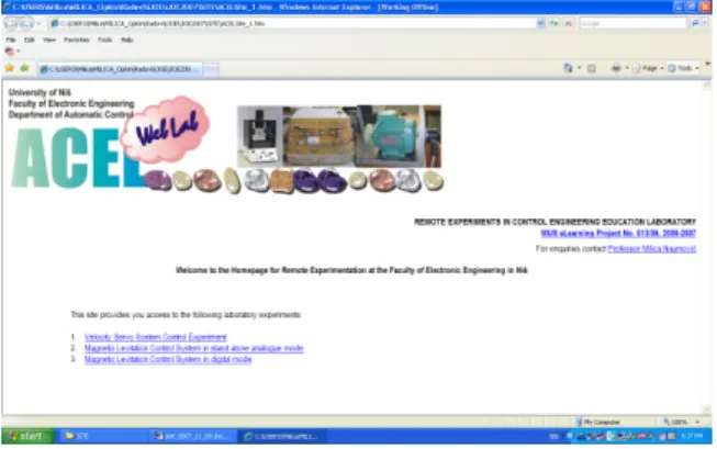
Some initial steps of design and building of a remote laboratory of automatic control at the Faculty of Electronic Engineering in Niš are presented in this paper. The main goal of this laboratory is to support learning in systems control allowing students to interact easily with a set of physical processes through the Internet. The student is able to run several experiments, change some control parameters, and analyze the results remotely. Fig. 1 visualizes the home web page
http://www.elfak.ni.ac.yu/~milica for remote control with the up to now experiment list:
1. Velocity Servo System Control Experiment;
2. Magnetic Levitation Control System in stand alone analogue mode;
3. Magnetic Levitation Control System in digital mode.
An additional feature of the remote laboratory is its architecture, with a special emphasis on an easy integration of other new processes for control experiments.
II. SYSTEM ARCHITECTURE
The WebLab ACEL (Automatic Control Education Laboratory) framework is based on client/server architecture where the communication is based on the standard Ethernet network with TCP/IP as protocol. In that kind of application client/server communication is possible via network protocols. For example, the hardware structure for web-based experiment with a didactic magnetic levitation system is shown in Fig. 2. Note four usual subsystems as follows [1]: 1. Local Controller, 2. Web Server, 3. Audio/Video Server, and 4. Client Terminal.
Local Controller is realized by using a PC equipped with appropriate interface cards. As Fig. 3 visualizes, depending on application and instruments to be controlled, the interference card may be general-purpose interference bus (GPIB), data acquisition card (DAQ), or digital signal processing card (DSP). Therefore, local controller may collect or give back information from/to various instruments (oscilloscope, spectrum analyzer, signal generator, frequency counter, etc.) in order to download or update the display on the remote client side.
Without doubt, the heart of the whole system is Web Server subsystem that enables the access to the web-based laboratory, the use and control of instruments, as well as performing experiments and obtaining results. From the viewpoint of topology, it is better to treat the Web server and the local controller as two separate subsystems [1].
Audio/Video (AV) Server provides users with a special kind of tele-presence in the remote laboratory. Namely,
Figure 2. Hardware structure of a Web-based laboratory
the captured video and audio streams are processed and temporarily stored in the memory of the server, before being pushed to the client for downloading and playing. Streaming the audio and video data can be carried out by a variety of commercial softwares. Note that in most applications, the use of single computer for the functions of the AV Server and Local Controller is quite possible.
Client or remote user is a subsystem connected to the Web Server. The user may browse the ACEL laboratory, and perform the experiments in the web-based laboratory with minimum software requirements.
III.
A.
EXPERIMENTAL SETUP
At this moment, ACEL WebLab integrates two control systems: velocity servo system setup and didactic magnetic levitation system. Recall that the main purpose of creating a web-based laboratory is the use of remote lab experiments as a special complement to the existing lab sessions. Using the possibility of sharing the laboratory resources among different faculties, the range of experiment could be extended.
Velocity Servo System Setup
The experimental velocity servo system setup consists of several functional elements as follows: AC motor with tachometer, power amplifier, modulator, demodulator, compensator, error detector. They are designed as the separate units with the possibility of their mutual cascade connection. Laboratory model, made at the Department of Automatic Control, is shown in Fig. 4(a). Notice that convenient sockets on the front panel allow us to quickly connect all system elements that are also individually denoted by the appropriate principle electrical scheme, which is described in detail in [2].
Control object is AC induction motor EVERSHED FAF G3B. As a part of motor equipment, the AC tachometer measures the shaft speed and produces voltage that is proportional to the measured value. This signal represents the main feedback signal. It is compared with the reference voltage, which is set by a potentiometer on the front panel (Fig. 4(b)). In order to stabilize the whole system, by using the voltage of the motor command phase, a local stabilization feedback is also established. To
(a)
(b) Figure 4. Photograph of velocity control system setup conduct the velocity servo system experiment, a set of connecting leads and an oscilloscope are needed.
B.
IV.
A. Didactic Magnetic Levitation System
As reported in vast control engineering education literature, the magnetic levitation process is from an educational viewpoint highly motivating and suitable for laboratory experiments and classroom demonstrations. A classical magnetic levitation control experiment is presented in the form of laboratory portable equipment given in Fig. 5. The complete purchase of MagLev System 33-006 [3] was supported by WUS-Austria [4] under the Grant C.E.P. No. 115/2002. Due to its nonlinear and unstable nature, this attraction-type levitator system is a very challenging plant [5]. The suspended body is a hollow steel ball of diameter and mass. Note
that both analogue and digital control solutions can be implemented. All this results in a visually attractive system with convenient time constants.
25 mm 20 g
The equipment is with built-in power supply and in the analogue mode capable of stand-alone operation without any computer control software. Quick changes of analogue controller gain and compensation components are enabled with convenient sockets on the enclosure panel, shown in Fig. 6. Note that the position of the sphere may be adjusted using the set-point control, whereas the system stability may be varied using the gain control.
In the digital mode, the MagLev System operates with MATLAB® /Simulink software. The Magnetic Levitation Unit and the Interface Module (denoted with 1 and 2 in Fig. 5) should be linked to each other with lead connections. The Advantech PCI1711 Card (component 3 in Fig. 5) is also inserted into a computer PCI slot, and connected with the Feedback SCSI Adapter box (component 4 in Fig. 5) using the SCSI cable. Feedback Software for Simulink is provided for the implementation of control algorithms and interfacing between the PC and the MagLev system hardware. Therefore, the system operates within a MATLAB®environmentwhich allows the system parameters to be determined and the system to be modeled. Namely, MATLAB® /Simulink and Real-Time Workshop (RTW) are used for control algorithm development, simulation, and rapid executable code generation. Digital controller with determined parameters can be used to run the hardware and the results of the actual control performance can be seen and analyzed. Additional student developed control algorithms may be also tested. Moreover, in the case of the web-based laboratory experiments, the final goal is for students to build their own experiment from home [6, 7].
SOFTWARE COMPONENTS AND SOME ELEMENTS OF REMOTE CONTROL
To perform the remote experiment in ACEL laboratory, the "LabVIEW Run Time Engine" and a standard web browser are needed. Therefore, the web-based laboratory was designed with minimum student's software requirements.
Remote controllable LabVIEW virtual instruments LabVIEW is a general-purpose program development environment for creating tests, measurements and control applications [8]. As its heart, the graphical programming, formally named G language, includes extensive libraries of functions for many programming tasks, as data acquisitions, GPIB and serial instrument control, data analysis, data presentation and storage. The programs written using G language are also called virtual
instruments (VIs) because, thanks to their appearance and easy operation, actual instruments can be imitated. A VI consists of an interactive user interface named front panel, block diagram that serves as the source code, and subprogram that enables VI to be called from VIs of higher level.
Moreover, LabVIEW development system offers several methods for remote access to application via TCP/IP protocol without additional programming. Namely, if LabVIEW is also installed on the client computer, the remote access to front panel of each VI can be provided. Since National Instruments integrated the LabVIEW Internet Server as a part of LabVIEW environment, the development of remote laboratories has become much easier. Using the LabVIEW Web server to publish appropriate VIs that can be remotely controlled via the Internet, the client needs to install the "LabVIEW Run Time Engine" which is about 23 . It includes libraries and files required to start LabVIEW application on client computer. Web Browser plug-in, used in remote control of application via Web Browser, is also part of Run-time engine. This runtime engine is available for free via the National Instruments Drivers CD or via download from the National Instruments ftp server. However, this download is done automatically if a client wants to connect and access the front panel for the first time.
MB
Note that the Web Server is quite independent from the client operating system, that is, it works with Windows, Linux and Mac operating systems. Also, the virtual instrument can be remotely observed or controlled by using standard web browser, as Internet Explorer, Netscape, Mozilla, Firefox and Opera, that are the most used ones. Other important aspects to be taken into account are the scheduling process and the secure access. Obviously, the remote laboratory can not be an open system. Moreover, Web Server configuration panel allows defining IP address or computer name which provides remote viewing/controlling experiments.
With LabVIEW 8.0 several virtual instruments have
been created. Recall that the VI can be included in an HTML file, which can be created either manually or by means of the LabVIEW web publishing tool. At this moment, regarding the scheduling, in ACEL laboratory are only two physical systems available for several potential users. Note that a remote user can fully access the user interface that appears on the web browser, as well as have complete control of the remote application. To avoid possible misunderstanding, only one client can control the application at a time. Other users can point their web browser to the same URL to view the started remote experiment. Naturally, to prevent monopolization possibility, a fixed amount of time (about 15 minutes) is assigned to each experiment session. After that time the user is automatically disconnected, and the process is available for the next potential user. Also, in case of need, the Lab Controller is allowed to reestablish the full control. Concretely, in order to control of the VI, the client has to request control by selecting "Request Control of the VI" by right clicking anywhere on the posted front panel where a short cut menu appears. User access control is managed by LabVIEW Web Server by default, without requirements for additional programming effort.
B. Examples of realized virtual instruments
Having in mind that it is important for the user to have a sense of presence in the laboratory, through the realized interfaces it is possible to start and stop experiments, as well as to observe control object behavior though some signal plots and live video window. Namely, with the applied WebcamXP software, the videos captured by the several web cameras, located in laboratory, can be published in the form of a HTML page, sent to the client side and played. Thus, the live video and some online data plots embedded into the appropriate VI front panel allow the user to view the real process while the experiment is in progress. WebcamXP is the powerful webcam streaming software, which offers unique features and ease of use to let you broadcast and manage up to 100 video sources per
Figure 8. The remote experimental front panel of maglev.vi in a classical web browser computer [9]. To deal with webcamXP issues, ActiveX
control is employed.
In creating our VI programs the Tektronix TDS1002 digital oscilloscope is used and controlled. Both virtual instruments, presented in this paper, serve Tektronix digital oscilloscope, which is a very good tool for acquiring, measuring, and displaying appropriate waveforms. Before start of acquisition, in order to control digital oscilloscope, the remote user can change vertical gain of the channels, set time per division for the main time base, position the waveform horizontally on the display, establish coupling (AC DC GND ) on the specified channel, as well as set trigger adjustments.
Fig. 7 shows the front panel of the LabVIEW virtual instrument named velocity.vi, which has been used for serving start/stop tasks and fly data visualization for the velocity servo system, given in Fig. 4(a). The servo system model is connected to the local Lab PC using RS-232 serial connection. In addition to online input/output signals monitoring, in the defined time interval the windowed RMS (root mean square) calculation of these signals is performed and results are also displayed. Thus, at the end of the experiment, the remote user is able to make a response-based identification of the whole system.
A web page created in LabVIEW environment for remotely monitoring and controlling the magnetic levitation equipment in stand alone analogue mode is presented in Fig. 8. By using 'start' button on the top center part of the front panel, the application can be started. Notice that at the moment, the problem of the remote placement of the sphere among the vertical axis of the electromagnet is still not realized adequately. This is one of the basic problems, because the measured ball position is determined from an array of infrared transmitters and detectors positioned in such a way that the infrared beam is intersected by the sphere. For now, in the interface application it is expected that, when the
initial procedure is completed and after the sound signal, the laboratory technician should place the ball along the electromagnet vertical axis.
When the experiments are completed, the remote user can save some data relating to the relevant signals in ASCII data files, as well as the pictures of the whole front panels in a JPEG format [10].
In the digital mode the magnetic levitation system operates in MATLAB®/Simulink environment. Recall, that after the experiment is completed, a special report of this experiment can be generated. At the moment the web site (shown in Fig. 1) offers Internet access and downloading the generated report to people interested in using the lab experiment remotely. In future work in this area more attention will be paid to remotely digital controlling the magnetic levitation equipment and ability to call a LabVIEW VI from the MATLAB®/Simulink environment or vice versa.
V. CONCLUSION
A web-based laboratory at the Faculty of Electronic Engineering, University of Niš was established in order to support learning of automatic control. The remote user is able to control both the computer and the several pieces of equipment through an appropriately designed graphical user interface running on the client computer. The control laboratory is based on the well-known LabVIEW and the realized virtual instruments provide the ability for online parameter tuning, signal monitoring, online analysis, as well as teleoperation without additional programming.
This paper presents some first insights into the design and implementation of a remote laboratory for supporting e-studies in system control. Future work in this area will concentrate on extending the range of experiments available for remote control. The software and hardware architectures have been designed to simplify the connection of new control processes.
REFERENCES
[1] C.C. Ko, B.M. Chen, and J. Chen, Creating Web-based Laboratories. Springer-Verlag, London Limited, 2004.
[2] Č. Milosavljević, User Guide-book for Lab Exercises in Automatic Control. Faculty of Electronic engineering, Niš, 1987.
[3] Feedback Instruments Limited, available at http://www.fbk.com/ (accessed on August 11th 2007).
[4] http://www.wus-austria.org (accessed on August 11th 2007). [5] M.B. Naumović, “Modeling of a didactic magnetic levitation
system for control education,” Proc. TELSIKS2003, Niš, pp. 783-786, October 2003.
[6] M. Casini, D. Prattichizzo, and A. Vicino, “The automatic control telelab: A Web-based technology for distance learning,” IEEE Contr. Sys. Mag., vol. 24, no. 3, pp. 36-44, June 2004.
[7] T.F. Junge, and C. Schmid, “Web-based remote experimentation using a laboratory-scale optical tracker,” Proc. American Control Conf., Chicago, IL, pp. 2951-2954, 2000.
[8] National Instruments Corporation . LabVIEW User Manual. TX: National Instruments Corporation, 1998.
[9] http://webcamxp.com (accessed on August 11th 2007).
[10] D. B. Živanović, M. Z. Arsić, and D.B. Denić, “Virtual measurement system for remote testing of smart transducers,” Proc. TELSIKS2005, vol. 2, September 2005, pp. 615-618.
AUTHORS
Milica B. Naumović is with the University of Niš, Faculty of Electronic Engineering, Department of Automatic Control, A. Medvedeva 14, Niš, Serbia (e-mail: nmilica@elfak.ni.ac.yu).
Dragan Živanović, is with the University of Niš, Faculty of Electronic Engineering, Department of Measurement, A. Medvedeva 14, Niš, Serbia (e-mail: dzile@elfak.ni.ac.yu).
This work was supported in part by the WUS Austria under Grant eLearning No 013/2006.
Manuscript received September 20, 2007. Published as submitted by the authors.