n
Interior Retrofit for 1960s and 1970s Two-Storey Houses
n>75% Space Heating Energy Savings
RetRofit foR eneRgy savings
One of the best ways to reduce the energy consumption of an existing house is to add insulation to the roof, walls and basement, upgrade windows and doors, and seal cracks, leaks and holes. These improvements, called “energy efficiency building envelope retrofits,” help to reduce heat losses in the winter and heat gains in the summer, and should result in lower energy bills, improved comfort and reduced outside noise intrusion.
This fact sheet provides guidance for interior energy efficiency building envelope retrofits to 1960s and 1970s two-storey houses that can reduce space heating energy consumption by 75 per cent or more. It describes the starting point (what you have now), air-sealing and insulation options to achieve the targeted energy savings, technical considerations to keep in mind in the planning of the retrofit project, and general precautions.
What You Have Now
The pre-retrofit construction of a 1960s or 1970s two-storey house will vary depending on its age and location and on whether any upgrades have already been completed. The building envelope of a typical 250-m2 (2,691-sq.-ft.) house of this
vintage with a finished basement will likely be clad with masonry, siding or stucco. Figure 2 illustrates common materials, insulation RSI-values (R-values), and assemblies for this type of building, subject to regional variations. Houses such as these are generally quite leaky with measured airtightness values averaging above 6.0 air changes per hour (ACH50).
Houses built in the 1960s and 1970s also tend be lightly insulated. It is common to find attics with a single layer of insulation and walls with insulating values that are half that required in new homes. Basements usually have modest levels of insulation, if any at all. Fortunately, there are many opportunities to improve the energy
efficiency of the building envelope. Insulation, air sealing and window technology have evolved significantly. For example, higher RSI-value (R-value) insulation is now available; low-emissivity coatings, gas fills and superior seals and spacers improve the thermal performance of windows considerably; and airtightness techniques are better understood.
To achieve over 75-per-cent space heating energy savings, air tightening and insulation values should be increased in all of the critical areas of the building envelope: roof or attic, above-grade walls, windows and doors, below-grade walls and basement floor slab. Figure 3 shows a general approach to retrofitting the same wall shown in figure 2—from the attic to the basement.
Figure 1: Two-storey detached house
INTERIOR RETROFIT The building envelope can be retrofitted from either the exterior or the interior. The choice will largely depend on the house’s interior and exterior finishes, layout and construction, lot line setback requirements, other renovation needs and whether or not the house will be occupied during the renovation. There are several advantages to air tightening and insulating a house from the interior. An interior retrofit can be done year-round; it doesn’t affect exterior cladding; it may cover cracks, holes and thermally conductive materials (called ‘thermal bridges’); and it doesn’t reduce distances to property lines.
Figure 2: Pre-retrofit section through roof, walls, floors and basement slab
1
2
2. Above-grade walls
n 38 mm x 89 mm (2” x 4”) wood-frame walls. The stud cavity may
contain fibreglass batt insulation, providing a nominal RSI-2.0 – 2.6 (R-11 – 15).
3. Windows and doors
n Single- or double-glazed with wood or vinyl frames.
4. Below-grade walls
n Concrete or concrete block, may be uninsulated or may have
wood-frame walls filled with fibreglass batt insulation, providing a nominal RSI-1.1 – 2.2 (R-6 – 12).
1. Roof and attic
n Fibreglass or cellulose insulation, providing a nominal RSI-4.5 – 5.5
(R-25 – 31).
5. Basement floor slab 3
4
Figure 3: Post-retrofit section through roof, walls and floors
1
2
2. Above-grade walls
n Install interior insulation and wood furring.
n Install polyethylene vapour retarder and gypsum board finish.
3. Windows and doors
n Replace windows with triple-glazed, low-e, argon-gas fill, low-conductivity
frames with insulated spacers.
n Install insulated doors.
n Install closed-cell spray foam between windows and doors, and
rough openings
4. Below-grade walls
n Install closed-cell spray foam insulation or extruded polystyrene (XPS)
insulation (or a combination of spray foam and batt insulation).
1. Roof and attic
n Add or extend insulation vents (guards).
n Spray foam on top of ceiling and add blown-in insulation above ceiling
(or additional fibrous insulation over existing attic insulation).
5. Basement floor slab
n Install extruded polystyrene (XPS) insulation over existing floor slab. n Install new sheathing and finished floor.
3
4
BUiLDing enveLoPe RetRofit
MeasURes foR sPaCe Heating
eneRgy savings
Taken together, the following energy-efficient retrofit measures should result in space heating energy savings of 75 per cent or more:
n Improve the airtightness to 1.0 ACH
50 or lower.
n Add insulation in the roof or attic.
n Add insulation on the interior of below-grade
(basement) walls.
n Add insulation on the interior of above-grade walls. n Add insulation to the basement floor slab.
n Replace windows with best quality windows.
Improving airtightness by sealing cracks, holes and gaps in the building envelope is relatively inexpensive and has a big effect on reducing energy loss, making it the most cost-effective measure. In other words, it leads to the greatest savings of heating energy per dollar spent. Moreover, an airtight house gains the full benefit of all the other retrofit measures because air leakage can reduce the thermal resistance of some types of insulation. Because of this, all proposed retrofit options include increasing airtightness to 1.0 ACH50. Improved airtightness reduces air leakage into the house and may require improved mechanical ventilation, such as that provided by a heat recovery ventilator, to maintain acceptable indoor air quality. The measures required to achieve this level of airtightness can be determined by an energy audit.
The suggested total effective RSI-values (R-values) to achieve space heating energy savings of 75 per cent or more are as follows: RSI-10.6 (R-60) in the roof or attic, RSI-3.5 (R-20) in the below-grade walls, RSI-7.0 (R-40) in the above-grade walls, RSI-1.8 (R-10) in the basement floor slab, and RSI-1.0 (R-6) in the windows. Assuming that the pre-retrofit house has similar insulation levels to those outlined in figure 2, the approximate amount of insulation that should be added to each of the building envelope locations is shown in table 1.
Before planning a retrofit for a specific house, CMHC recommends that a qualified residential energy service provider undertake an EnerGuide audit of the house. The audit should measure the airtightness of the pre-retrofit house, suggest upgrades to the heating system, and locate areas where air leaks should be sealed and insulation should be added. Audits and ratings can be obtained from service organizations licensed under Natural Resources Canada’s EnerGuide program. For more information on finding a qualified service organization, visit http://oee.nrcan.gc.ca/residential/personal/16352.
Table 1: Suggested ACH50 and additional effective RSI-values (R-values) to achieve space heating energy savings of 75 per cent or more
ACH50 Value Retrofit Measures Space Heating Energy Savings (approximate) Add Insulation in Roof or Attic Add Insulation to Interior of Below-Grade Walls Add Insulation to Interior of Above-Grade Walls Add Insulation to Basement
Floor Slab Replace Windows
1.0
Option A: RSI-10.6 (R-60) Option B: RSI-8.8 (R-50)
teCHniCaL ConsiDeRations
Roof and attic
Insulation
Insulation can be added to the interior of the roof/attic space provided that there is sufficient depth. It is cost-effective and relatively easy to achieve high levels of insulation, that is, RSI-10.6 (R-60), in the attic space. This may also allow trade-offs with other areas of the house that are harder to insulate (such as the basement floor slab), while still achieving the desired space heating energy savings. To achieve RSI-10.6 (R-60), two options may be considered:
Option A: Remove any existing insulation and add about 50 mm (2 in.) of closed-cell spray foam insulation over the existing ceiling finish between the bottom chords of the roof trusses. Top up with additional fibreglass or cellulose batt or blown-in insulation to increase the effective insulation RSI-value (R-value) to the thermal levels outlined in table 1. The ‘effective’ insulation value accounts for the reduced insulation value of thermally conductive components in the assembly, such as trusses, rafters and studs, and is usually lower than the nominal value of the insulation itself.
Option B: Keep existing batt or blown-in insulation and top up with additional cellulose or fibreglass insulation above it. If this option is chosen, it is important to ensure air-barrier continuity by sealing all penetrations through the ceiling to the existing air barrier, likely the polyethylene sheet above the ceiling. When installing additional insulation in the attic space, ensure that a sufficient number of insulation baffles are installed along
the eaves of the roof to provide the required ventilation into the attic space and ensure the baffles are not blocked.
Airtightness
The existing air barrier at the attic, if present, is likely polyethylene above the gypsum board ceiling. The spray foam insulation in this retrofit provides a continuous air barrier at all ceiling penetrations (such as electrical boxes for light fixtures, bathroom fans and ducts, and plumbing vent stacks). Be sure to seal the attic hatch with a compressible gasket. Ensure air-barrier continuity at the roof-to-wall connection by sealing the polyethylene in the roof to the wall air-barrier system. This is best accomplished by spraying closed-cell foam insulation into the space between the ceiling and the insulation baffles (guards), making sure the spray foam connects the ceiling and wall air barriers (that is, polyethylene). The spray foam acts as insulation, vapour retarder and air barrier.
Vapour retarder
The polyethylene sheet located above the ceiling gypsum board or the closed-cell spray foam insulation can provide resistance to vapour diffusion into the attic space.
Water penetration control
The roof assembly sheds all exterior moisture by gravity drainage over shingled materials. The underlayment beneath the shingles provides a secondary line of protection. During the retrofit, pay careful attention to the condition of the roof sheathing (as viewed from the underside) and the attic space. If there are indications of moisture penetration (water staining, mold or wood rot), further investigation and repair will be required.
Figure 4: Section through roof and attic
EXISTING ROOF ASSEMBLY INSULATION BAFFLE NEW BLOWN-IN FIBREGLASS OR CELLULOSE INSULATION OVER EXISTING
NEW CLOSED-CELL SPRAY FOAM INSULATION
EXISTING POLYETHYLENE AIR BARRIER AND VAPOUR RETARDER, WITH AIR-BARRIER IMPROVEMENT AT CEILING
Important considerations
Ensure there is adequate attic ventilation. Check that insulation baffles are installed properly, and vents at soffits and ridges are present and not blocked. If there are no baffles between each pair of rafters or trusses, these should be added as part of the retrofit.
Above-grade walls
Insulation
To retrofit above-grade walls from the interior, a double-stud wall will provide space for the additional insulation necessary to attain the thermal requirements outlined in table 1. This is done by removing the existing drywall and polyethylene, and building a second row of 38 x 89 mm (2 x 4 in.) wood-stud framing with a gap between the stud walls. The total depth of the cavity must be sufficient to contain the thickness of insulation needed to produce the effective RSI-value (R-value) in table 1. Fill the wall cavity with insulation and install a new polyethylene vapour retarder/air barrier and gypsum board finish (see figure 5). Thicker walls will result in some loss of interior floor space when retrofitting from the interior. The
required space can be reduced by using insulation with a higher RSI -value (R-value) in the existing wall and in the new wall cavity.
Airtightness
Airtightness is achieved by installing an air barrier on the interior of the insulation. This can be accomplished with polyethylene that is properly sealed and detailed at connections, or taped and sealed gypsum board. Connect all components of the air-barrier system at all interfaces and joints throughout the house (such as windows, wall to roof, wall to floor, etc.) and across interior partitions where they intersect with exterior wall assemblies or ceilings.
Important considerations
With interior wall retrofits, the floor joists extending to the exterior of the wall assembly can create a thermal bridge where increased heat loss occurs. This can be minimized by adding two layers of 50 mm (2 in.) XPS insulation plus 50 mm (2 in.) of closed-cell spray foam insulation inboard of the rim joist, between the floor joists around the perimeter of the foundation. Electrical services may also need to be relocated to the inside face of the new wall.
1 A drained and vented rainscreen wall with an air space between the cladding and sheathing is recommended.
Figure 5: Section through above-grade wall
EXISTING CLADDING, ANY TYPE EXISTING BUILDING PAPER EXISTING 38X89 MM (2X4 IN.) FRAMING
GAP BETWEEN NEW AND EXISTING FRAMING
NEW 38X89 MM (2X4 IN.) FRAMING NEW BLOWN-IN DENSE PACK FIBREGLASS OR CELLULOSE INSULATION
NEW POLYETHYLENE (AIR AND VAPOUR BARRIER)
EXISTING SHEATHING EXISTING GYPSUM BOARD
XPS AND CLOSED-CELL SPRAY FOAM BETWEEN FLOOR JOISTS
Vapour retarder
Polyethylene provides the primary vapour retarder layer. Alternatively, vapour-retarder paint, in combination with sealant at joints and penetrations, may provide adequate vapour control.
Water penetration control
The existing cladding acts as a water-shedding surface. The water-resistive barrier is the sheathing membrane, typically building paper in older houses. Ensure that exterior water is prevented from entering the wall, and there is a vented air space between the cladding and wall sheathing to enable the wall to dry1.
Pay careful attention to the condition of the exterior sheathing (as viewed from the inside). If there are indications of moisture penetration (water staining, mold or wood rot), further investigation and repair will be required.
Windows and doors
Insulation
Doors with insulated cores and energy-efficient windows having either double, or preferably, triple glazing, and low-conductivity frames (vinyl or fibreglass) can provide significant energy savings to existing homes. The windows should have low-e coating(s), argon-gas fill and low-conductivity insulating glass edge spacers that can be customized depending on performance needs. For instance, a low-e coating applied to the inside surface of the outside pane will reflect much of the sun’s energy back to the exterior, thereby reducing helpful solar heat gains in the winter. If the coating is applied to the outside surface of the inside pane, this will allow more of the sun’s energy into the house and will also help reflect internal heat back into the house to reduce the space heating requirements. Look for windows with overall thermal resistance values in accordance with levels shown in table 1 or better.
Replacing architecturally significant doors may not be desirable, but poorly insulated doors can cause a significant loss of energy in a well-insulated house, particularly in cold climates. If replacing the doors, look for doors with insulated cores and thermal resistance values greater than RSI-1.0 (R-5.7). Consider installing storm doors outside the existing exterior doors to reduce heat loss in winter. During the summer months, the storm door vent should be open to allow the heated air between the doors to escape to the exterior, thereby preventing damage to the door components due to excess heat buildup.
Where possible, consider exterior shading devices, such as roof overhangs and awnings, to limit solar heat gain on south-, east- and west-facing windows during the summer. For south-facing windows, as a rule of thumb, the awning or overhang should extend out a distance equal to one-third of the window height to provide shading.
Airtightness
It is important to provide an airtight interface between the windows/doors and the walls. This can be accomplished by installing a backer rod and sealant, or spray foam insulation, in the gap between the rough opening and the window or door (see figure 6). Operable windows (such as awning, sliding, casement, tilt-turn, or single- or double-hung windows) are prone to leakage over time; gaskets, caulking, tapes, seals and weatherstripping break down with continued use. Consider selecting windows with low air-leakage characteristics and durable seals and gaskets.
Vapour retarder
The windows and doors can act as vapour retarders provided that the connections between the windows/doors and walls are airtight.
Water penetration control
It is important to provide good sealing and water shedding where the window/door sits in the wall. Provide a waterproof “sill dam” underneath the window and slope it outwards to the exterior of the wall. Ensure the sill water barrier is effectively sealed to the window frame and the water barriers in the existing or retrofitted wall assembly.
Figure 6: Window installation (exterior view)
1. TRIplE-glAzEd WIndoW WITH loW-conducTIVITy fRAmE
2. foIl-fAcEd, SElf-AdHEREd mEmbRAnE, TApEd To polyETHylEnE foR AIR-bARRIER conTInuITy 3. polyETHylEnE AIR And VApouR bARRIER 4. doublE-STud WAll ASSEmbly
5. ExISTIng SHEATHIng pApER 6. ExISTIng clAddIng (Any TypE) 7. Wood TRIm
8. SIll flASHIng complETE WITH End dAmS 9. WIndoW SHImS
10. bAckER Rod And SEAlAnT, oR SpRAy foAm (noT SHoWn), To connEcT WAll AIR bARRIER To WIndoW 1 4 5 6 7 8 2 9 3 10
Choose windows with appropriate water penetration
resistance. This is particularly important for houses in exposed locations or climates with high wind and rain loads.
Important considerations
It is important to carefully seal the window interface with the wall assembly in order to achieve a continuous air and water barrier. Many different approaches are possible depending on the window type, the wall assembly, and the position of the window within the rough opening2.
Interior retrofits to improve the thermal performance of the building envelope will result in a thicker wall assembly. This means the window can be installed in one of three positions: in line with the exterior surface, in line with the interior surface, or in the middle of the rough opening as shown in figure 6. Installing the window in line with the interior wall will help to reduce the potential for condensation on the glass as it is in a warmer location but may require deep sill flashings and window trims on the exterior. This reduces window exposure to wind-driven rain but relies more on flashings to deflect water. Installing the window in the middle of the wall, as shown, requires less exterior flashing and trim, and provides space for an interior window sill.
Below-grade walls
Insulation
Insulation can be applied on the interior of the foundation wall to the full height of the below-grade wall, extending through the joist space to the above-grade wall (see figure 7). The below-grade foundation walls can be retrofitted from the interior by spraying closed-cell foam insulation against the inside of the foundation wall in sufficient thickness to attain the thermal value outlined in table 1. Extruded polystyrene (XPS) insulation can be used as an alternative to spray foam insulation, with joints taped to prevent interior air from reaching the concrete foundation wall. Closed-cell spray foam can also be installed at the rim joist between the floor joists to reduce thermal bridging and improve airtightness at this location.
To reduce costs, 25 to 50 mm (1 to 2 in.) of closed-cell spray foam insulation may be applied to the foundation wall followed by 38x89 mm (2x4 in.) wood framing filled with fibreglass batt insulation or mineral wool.
Airtightness
The retrofit should improve the airtightness at the below-grade to above-below-grade wall connection. Closed-cell spray foam on the inside of the foundation wall provides a continuous
2 Refer to CMHC’s Design, Selection and Commissioning of Window Installations.
Figure 7: Section through below-grade wall
XPS AND CLOSED-CELL SPRAY FOAM INSULATION BETWEEN FLOOR JOISTS GYPSUM BOARD
38×64 MM (2×3 IN.) INFILL WOOD FRAMING (EMPTY) CLOSED-CELL SPRAY FOAM INSULATION
EXISTING CONCRETE FOUNDATION WALL
Vapour retarder
It is also important to control water vapour for the entire below-grade assembly. A vapour retarder is required at the interior of the insulation to prevent condensation from occurring on the cold foundation wall and in the wall framing. In this retrofit, the closed-cell spray foam insulation is a vapour retarder, so no additional vapour retarder is required. Check with your local building department to determine if additional vapour resistance is desired.
Water penetration control
This retrofit strategy relies on the existing foundation assembly to control and drain exterior ground water. If the existing foundation appears to have drainage or leakage problems, further investigation and repairs should be completed.
air barrier as well as a vapour barrier. Spray foam insulation between the floor joists at the perimeter of the basement ceiling will minimize thermal bridging at this location and create a continuous air barrier from the below-grade wall to the above-grade wall.
Important considerations
Proper detailing is required where the interior partition walls meet the exterior foundation wall. Install spray foam insulation around the wood framing at these locations.
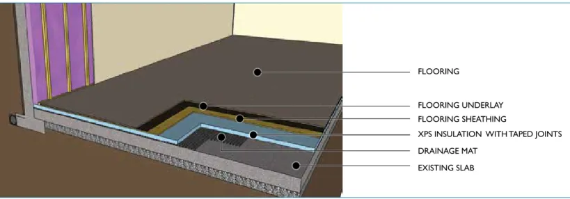
Basement floor slab
Insulation
To improve energy efficiency in new home construction, insulation may be installed below the slab. However, in the energy retrofit of existing basement concrete slabs, one must insulate the slab from the interior. This is done by removing the interior flooring (if the basement is finished) and installing XPS board insulation (in sufficient thickness to meet the thermal requirements outlined in table 1). Tape all joints and install floor sheathing and finished flooring above the insulation (see figure 8). Insulation thickness may be limited by
the amount of floor-to-ceiling height available in the basement. Consider using insulation with a high RSI-value (R-value) per unit thickness to minimize the floor-to-ceiling height reduction.
Airtightness
An air barrier is required on the interior side of the insulation to prevent warm interior air from contacting the cold
concrete slab. This can be achieved by taping the joints of the XPS insulation, and by connecting the floor air barrier with the wall air barrier. A continuous and effective basement air barrier should also reduce infiltration of soil gases
(moisture, radon) into the occupied spaces.
Vapour retarder
XPS insulation is an adequate vapour retarder; therefore, an additional vapour control layer is not required.
Water penetration control
The existing foundation and slab assembly serves as the water control layer. When undertaking this retrofit look for signs of water ingress through, or moisture problems on, the existing floor slab. Any existing water ingress problems will require further investigation and repair.
Figure 8: Retrofit to basement floor slab
FLOORING
FLOORING UNDERLAY FLOORING SHEATHING
XPS INSULATION WITH TAPED JOINTS
EXISTING SLAB DRAINAGE MAT
aDDitionaL DetaiLs
A 1960s or 1970s two-storey house may have other areas where insulation should be installed, or that may require more attention to air sealing. Two common areas are shown below.
Figure 10: Section through garage roof at insulated wall
GARAGE AIR-BARRIER
Figure 9: Section through exposed (projecting) floor
AIR-BARRIER
Exposed floors
Floors at the ground level or upper storeys that have either ground or exterior space below them should be insulated. For example, this may occur at a bay window (see figure 9).
Closed-cell spray foam and XPS insulation can be installed between the floor joists at exposed floor locations. Install several layers of XPS insulation first, to reduce the thickness of spray foam that is required. In the air-barrier continuity line, seal the polyethylene to the bottom plate, and caulk between the bottom plate and the floor sheathing.
Garage wall
It is important to install a continuous air barrier between the interior space and the garage (see figure 10). Walls that are adjacent to the garage should be treated as exterior walls and insulated using the double-stud assembly. If interior living space is located above a garage area, insulation should be installed in the floor space, and the floor assembly should be made airtight and continuous with the air barriers in the adjacent walls. In the air-barrier continuity line, seal the polyethylene to the bottom plate, and caulk between the bottom plate and the
eneRgy savings
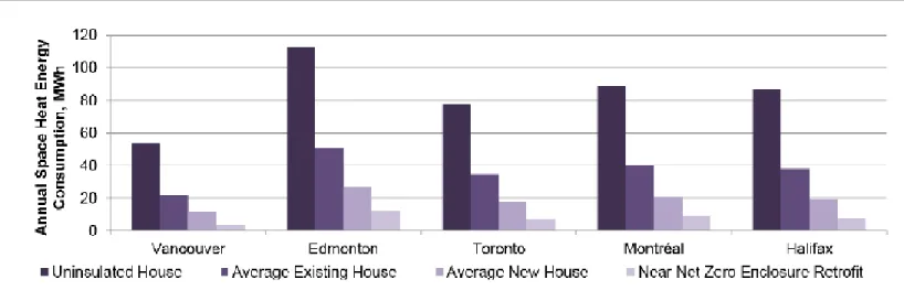
Heating energy consumption can be significantly reduced when high insulation values are used, thermal bridging is minimized and airtightness is improved. Specific retrofit costs, energy savings and payback periods depend on many factors, including the location, design and construction of the existing house, and the level of retrofit done. Because of this, it is important to look at costs and savings on a case-by-case basis.
The graph below (see figure 11) shows annual heating energy consumption for a typical two-storey house in various Canadian climates with various levels of enclosure performance (all with the same mid-efficiency mechanical equipment). If a highly energy-efficient building envelope retrofit is completed, space heating energy consumption could be reduced by more than 75 per cent, depending on the existing construction and the level of enclosure retrofit performed.
Figure 11: Annual space heat energy consumption of houses with various insulation and airtightness levels in different locations across Canada
RefeRenCes
RDH Building Engineering, research report, Near Net Zero Energy Retrofits for Houses, CMHC, 2012.
Building Enclosure Design Guide – Wood-Frame Multi-Unit Residential Buildings
http://www.hpo.bc.ca/building-enclosure-design-guide
Renovating for Energy Savings – Case Studies: available online at http://www.cmhc.ca/en/co/renoho/reensa/index.cfm
A WORd OF CAuTION
Assess the condition of the house for pre-existing problems and anticipate the possible effects of the retrofit work on indoor air quality, building envelope durability, heating appliance performance or other possible performance issues, in order to avoid unintended consequences of a building envelope energy-efficiency retrofit.
pre-existing problems: The house may have moisture problems (high humidity, water leaks, dampness, mold, etc.) in the roof, walls, floors or foundation; indoor air quality problems (stale air, lingering odours, soil gas, pollutant emissions from household products, etc.); radon or other soil gases; structural sags, cracks and deflections; or the presence of hazardous materials such as asbestos, lead paint and rodent/bird waste. Pre-existing problems should be corrected prior to undertaking an energy efficiency building envelope retrofit so that the problems do not worsen.
Ventilation: A highly energy-efficient building envelope retrofit will provide a more airtight house, which is important for reducing energy consumption. However, this will also result in less incidental ventilation, which would otherwise be provided by a leaky enclosure. This can cause the air in the retrofitted house to seem stale and odours to linger longer. Odours from previously unnoticed sources (such as hobbies, pets or stored items) may become more apparent and more objectionable.
Therefore, energy-efficient mechanical ventilation should also be included in any home energy retrofit strategy. This can be accomplished by adding a heat recovery ventilator (HRV) or an energy recovery ventilator (ERV). This ventilation should improve occupant health and comfort.
building envelope durability: Installing additional insulation can increase the risk of moisture to the building envelope if inside and outside sources of moisture are not controlled.
Heating appliance performance: Reducing heat losses through the envelope may result in the existing furnace or boiler being oversized for the house. Oversized heating equipment does not operate efficiently as it tends to cycle on and off more frequently. Reducing air leaks in a house with chimney-vented furnaces, water heaters and fireplaces can reduce the amount of air needed for safe and efficient operation.
Consult with a qualified energy service provider, building professional, home inspector or contractor before the retrofit to better understand, and plan for, pre-existing conditions and possible unintended consequences of the retrofit project. Often, corrective measures can be planned that not only prevent problems but also add value to the overall project. For more information on retrofit and renovation considerations, visit CMHC’s website at www.cmhc.ca.
The information contained in this publication represents current research results available to CMHC. Readers are advised to evaluate the information, materials and techniques cautiously for themselves and to consult appropriate professional resources to determine whether information, materials and techniques are suitable in their case. The text is intended as general information only and project and site-specific factors of climate, aesthetics, practicality, utility and compliance with applicable building codes and standards must be taken into consideration. Actual reductions in energy consumption and savings will vary. Any reliance or action taken based on
©2012, Canada Mortgage and Housing Corporation Printed in Canada
Produced by CMHC 01-05-13