ADVERTIMENT. La consulta d’aquesta tesi queda condicionada a l’acceptació de les següents
condicions d'ús: La difusió d’aquesta tesi per mitjà del servei TDX (www.tesisenxarxa.net) ha estat autoritzada pels titulars dels drets de propietat intel·lectual únicament per a usos privats emmarcats en activitats d’investigació i docència. No s’autoritza la seva reproducció amb finalitats de lucre ni la seva difusió i posada a disposició des d’un lloc aliè al servei TDX. No s’autoritza la presentació del seu contingut en una finestra o marc aliè a TDX (framing). Aquesta reserva de drets afecta tant al resum de presentació de la tesi com als seus continguts. En la utilització o cita de parts de la tesi és obligat indicar el nom de la persona autora.
ADVERTENCIA. La consulta de esta tesis queda condicionada a la aceptación de las siguientes
condiciones de uso: La difusión de esta tesis por medio del servicio TDR (www.tesisenred.net) ha sido autorizada por los titulares de los derechos de propiedad intelectual únicamente para usos privados enmarcados en actividades de investigación y docencia. No se autoriza su reproducción con finalidades de lucro ni su difusión y puesta a disposición desde un sitio ajeno al servicio TDR. No se autoriza la presentación de su contenido en una ventana o marco ajeno a TDR (framing). Esta reserva de derechos afecta tanto al resumen de presentación de la tesis como a sus contenidos. En la utilización o cita de partes de la tesis es obligado indicar el nombre de la persona autora.
WARNING. On having consulted this thesis you’re accepting the following use conditions:
Spreading this thesis by the TDX (www.tesisenxarxa.net) service has been authorized by the titular of the intellectual property rights only for private uses placed in investigation and teaching activities. Reproduction with lucrative aims is not authorized neither its spreading and availability from a site foreign to the TDX service. Introducing its content in a window or frame foreign to the TDX service is not authorized (framing). This rights affect to the presentation summary of the thesis as well as to its contents. In the using or citation of parts of the thesis it’s obliged to indicate the name of the author
Hardware Design
of
Task Superscalar Architecture
Ph. D. Candidate: Fahimeh Yazdanpanah
Supervisors: Dr. Carlos Alvarez Martinez and Dr. Daniel Jimenez Gonzalez Computer Architecture Department, Universitat Politecnica de Catalunya
A thesis submitted for the degree of Doctoral (PhD)
Exploiting concurrency to achieve greater performance is a dicult and important challenge for current high performance systems. Although the theory is plain, the complexity of traditional parallel programming models in most cases impedes the programmer to harvest performance.
Several partitioning granularities have been proposed to better exploit con-currency at task granularity. In this sense, dierent dynamic software task management systems, such as task-based dataow programming models, benet dataow principles to improve task-level parallelism and overcome the limitations of static task management systems. These models implicitly schedule computation and data and use tasks instead of instructions as a basic work unit, thereby relieving the programmer of explicitly managing parallelism. While these programming models share conceptual similarities with the well-known Out-of-Order superscalar pipelines (e.g., dynamic data dependency analysis and dataow scheduling), they rely on software-based dependency analysis, which is inherently slow, and limits their scalability when there is ne-grained task granularity and a large amount of tasks. The aforementioned problem increases with the number of available cores. In order to keep all the cores busy and accelerate the overall application performance, it becomes necessary to partition it into more and smaller tasks. The task scheduling (i.e., creation and management of the execution of tasks) in software introduces overheads, and so becomes increasingly inef-cient with the number of cores. In contrast, a hardware scheduling solution can achieve greater speed-ups as a hardware task scheduler requires fewer cycles than the software version to dispatch a task.
The Task Superscalar is a hybrid dataow/von-Neumann architecture that exploits task level parallelism of the program. The Task Superscalar
com-abstraction, and thereby provides an unied management layer for CMPs which eectively employs processors as functional units. The Task Super-scalar has been implemented in software with limited parallelism and high memory consumption due to the nature of the software implementation. In this thesis, a Hardware Task Superscalar architecture is designed to be integrated in a future High Performance Computer with the ability to ex-ploit ne-grained task parallelism. The main contributions of this thesis are: (1) a design of the operational ow of Task Superscalar architecture adapted and improved for hardware implementation, (2) a HDL prototype for latency exploration, (3) a full cycle-accurate simulator of the Hardware Task Superscalar (based on the previously obtained latencies), (4) full design space exploration of the Task Superscalar component conguration (number and size) for systems with dierent number of processing elements (cores), (5) comparison with a software implementation of a real task-based pro-gramming model runtime using real benchmarks, and (6) hardware resource usage exploration of the selected congurations.
Keywords: Hardware Task Superscalar (HTSS), SimTSS, OmpSs, Nanos++ Runtime System, Hybrid Dataow/von-Neumann, Task Scheduler
This work is supported by the Ministry of Science and Technology of Spain and the European Union (FEDER funds) under contracts TIN2007-60625 and TIN2012-34557, by the Generalitat de Catalunya (contract 2009-SGR-980) and by the European FP7 project TERAFLUX id. 249013, http://www. teraux.eu. We would also like to thank the Xilinx University Program for its hardware and software donations.
Contents
List of Figures xiii
List of Tables xvii
1 Introduction 1 1.1 Motivations . . . 1 1.1.1 Problem Statement . . . 3 1.1.2 Objective . . . 4 1.1.3 Contributions . . . 5 1.2 Thesis Outline . . . 5
2 Background and Context 9 2.1 Von-Neumann Computing Model . . . 11
2.1.1 Parallelism in the von-Neumann Computing Model . . . 11
2.2 Dataow Computing Model . . . 13
2.2.1 Dataow Architectures . . . 14
2.2.2 Limitations of Dataow Models . . . 16
2.3 Hybrid Dataow/von-Neumann Architectures . . . 17
2.3.1 Evolution of Hybrid Architectures . . . 17
2.3.2 Taxonomies of Hybrid Models . . . 19
2.3.3 Models of Dataow/Control Flow Class . . . 22
2.4 Task-based Dataow Programming Model . . . 26
2.4.1 StarSs Programming Family . . . 26
2.5 Task Superscalar Architecture . . . 31
2.6 Related Work . . . 34
3 Design of Hardware Task Superscalar 37
3.1 Operational Flow of Hardware Task Superscalar . . . 39
3.1.1 Operational Flow of HTSS.1 . . . 39
3.1.2 Case Study . . . 47
3.1.3 Operational Flow of HTSS.2 . . . 49
3.1.4 Operational Flow of HTSS.3 . . . 50
3.2 Comparison of HTSS and its predecessor . . . 53
3.3 Summary . . . 56
4 Hardware Prototypes for Latency Exploration 57 4.1 Hardware Prototypes . . . 59
4.1.1 HTSS.1 Prototype . . . 59
4.1.2 HTSS.2 Prototype . . . 64
4.1.3 HTSS.3 Prototype . . . 64
4.2 Methodology of the HDL Design of HTSS . . . 66
4.3 Latency Exploration Results . . . 68
4.3.1 RTL Simulation Results . . . 68
4.3.2 Latency Comparison of HTSS Prototypes . . . 69
4.4 Summary . . . 73
5 Design Space Exploration of HTSS 75 5.1 Simulator for the Design Space Exploration . . . 77
5.1.1 Simulator Description and Usage . . . 77
5.1.2 Methodology . . . 81
5.2 Frameworks and Benchmarks of the Design Space Exploration . . . 83
5.2.1 Experimental Setup . . . 83
5.2.2 Benchmark Applications . . . 83
5.3 Design Space Exploration of HTSS . . . 87
5.3.1 HTSS for High Performance Computing . . . 87
5.3.2 HTSS design with limited workers . . . 98
5.3.3 Simple HTSS for Small Multicores . . . 100
5.4 Results of the Design Space Exploration . . . 102
5.4.1 Comparison of the Selected HTSS Congurations . . . 102 5.4.2 Comparison of HTSS to the Software Runtime Alternative (Nanos++)105
5.5 Summary . . . 112
6 Estimation of the Hardware Resources Usage of HTSS 113 6.1 Methodology and Experimental Setup . . . 115
6.1.1 Target Devices . . . 116
6.2 HTSS Modules Synthesis Results . . . 117
6.2.1 Memory Modules . . . 117
6.2.2 Main Modules . . . 121
6.3 Evaluation and Analysis of the HTSS Design . . . 123
6.4 Summary . . . 129
7 Conclusions and Future Work 131 7.1 Future Work . . . 134
Appendix A Denition of Common Fields 137
Appendix B Structures of Memory Modules 139
Appendix C Denition and Format of Packets 143
Appendix D Supplementary of SimTSS Results 151
List of Figures
1.1 Average task size and the number of tasks of dierent OmpSs applications
for 2048×2048 elements with dierent block size of tasks . . . 3
1.2 Speed-up obtained for dierent OmpSs applications for 2048×2048 ele-ments in a real execution with 12 cores . . . 4
2.1 Computing a loop using (a) the von-Neumann model,(b) a dataow model 14 2.2 DFG of a loop (a) the static and (b) the dynamic dataow . . . 15
2.3 Inter- and intra-block scheduling of organizations of hybrid dataow/von-Neumann architectures. (a) Enhanced Control Flow, (b) Control Flow/Dataow, (c) Dataow/Control Flow, and (d) Enhanced Dataow. Blocks are squares and big circles . . . 20
2.4 Dierent architectures of Dataow/Control Flow class (a) number of cores and year, (b) number of cores and size of blocks . . . 23
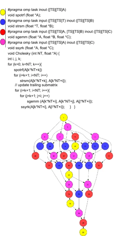
2.5 OmpSs implementation of the Cholesky algorithm and its dependency graph . . . 30
2.6 The Task Superscalar architecture (Figure based on [6]) . . . 32
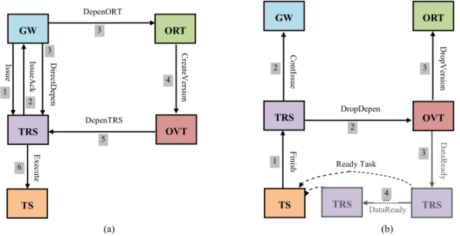
3.1 Operational ow of hardware Task Superscalar, (a) when a task arrives to the pipeline, (b) when a task is nished . . . 39
3.2 Operational ow of the GW . . . 41
3.3 Operational ow of the TRS . . . 41
3.4 Operational ow of the ORT . . . 42
3.5 Operational ow of the OVT . . . 42
3.7 Example of ve non-dependent tasks, (a) OmpSs program, (b)
Relation-ship between TRS entries and OVT entries . . . 48
3.8 Example of ve dependent tasks, (a) OmpSs program, (b) Relationship between TRS entries and OVT entries (producer-consumer chain) . . . . 49
3.9 Operational ow of the eORT module . . . 50
3.10 The operational ow of the improved GW (iGW) module . . . 53
3.11 The operational ow of the improved TRS (iTRS) module . . . 53
3.12 Operational ow of sending non-scalar dependences, (a) the original ver-sion, (b) the hardware version . . . 55
4.1 Hardware Task Superscalar architecture . . . 59
4.2 HTSS.1 prototype . . . 60
4.3 Structure of the memory modules: (a)VM, (b)DM, (c)TM . . . 61
4.4 Connections of a FIFO based on 4-step handshaking protocol . . . 62
4.5 HTSS.2 prototype . . . 63
4.6 HTSS.3 prototype . . . 65
4.7 The interconnection between TRSs/iTRSs and GW/iGW (a) HTSS.1 and HTSS.2 prototypes, (b) HTSS.3 prototype . . . 65
4.8 Steps of implementing a logic design with an FPGA . . . 66
4.9 Time scheduling, in cycles, of a) 5 non-dependent tasks on HTSS.1, b) 5 non-dependent tasks on HTSS.2, c) 5 non-dependent tasks on HTSS.3, d) 5 dependent tasks on HTSS.1, e) 5 dependent tasks on HTSS.2, f) 5 dependent tasks on HTSS.3 . . . 72
5.1 High level description of SimTSS . . . 78
5.2 Workow of SimTSS usage . . . 80
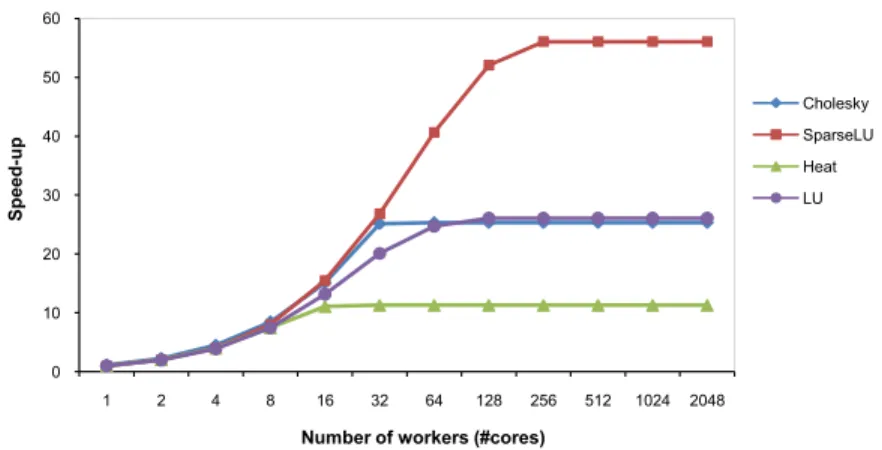
5.3 Summary of speed-up of a HTSS with more-than-enough resources . . . 88
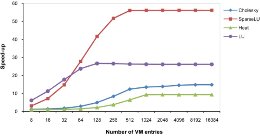
5.4 Speed-up obtained as a function of the number of Task Memory entries . 89 5.5 Speed-up obtained as a function of the number of Version Memory (VM) entries . . . 90
5.6 Speed-up obtained as a function of the number of eORT modules . . . . 91
5.7 Speed-up obtained as a function of the DM entries with LSB and Pearson-like hash . . . 92
5.9 Eect of changing the number of modules maintaining the sizes of the memories . . . 95 5.10 Eect of dierent number of TM entries on the performance of a system
with 32 workers . . . 98 5.11 Eect of dierent number of VM entries on the performance of a system
with 32 workers . . . 99 5.12 Eect of dierent number of DM entries on the performance of a system
with 32 workers . . . 100 5.13 Speed-ups obtained with only one TRS and one eORT modules when
changing the total memory sizes and the number of workers . . . 101 5.14 Speed-ups obtained for dierent number of workers with the Parallelism,
ZeroTSS, BigConf, HPCConf and MinConf congurations . . . 104 5.15 Comparison of Nanos++ and HTSS with dierent number of threads and
block size for the same problem size (2048) . . . 109 5.16 Number of tasks and average task size in cycles of Cholesky 2048, SparseLU
2048, Heat 2048 and LU 2048 as function of the block size . . . 110 5.17 Speed-ups obtained for dierent parallelizations of the Cholesky, SparseLU,
Heat and LU applications with dierent HTSS congurations. First num-ber is the problem size and the second numnum-ber is the block size . . . 111 6.1 LUTs usage of the modules of HTSS.3 (a) with distributed memories, (b)
with BRAM memories . . . 124 6.2 LUTs usage of the modules of HPCConf (a) with distributed memories,
(b) with BRAM memories . . . 124 6.3 Percentage of LUTs of the devices used by the HTSS.3, HPCConf and
MinConf (a) with distributed RAMs, (b) with BRAMs . . . 125 6.4 Percentage of memory logics of the devices used by the prototypes, (a)
List of Tables
2.1 Comparison of the hybrid dataow/von-Neumann architectures in the class of dataow/control ow class. DF, CF, and DFG stand for dataow,
control ow and dataow graph, respectively . . . 24
3.1 Denition of the packets . . . 40
4.1 Characteristics of the memory modules . . . 61
4.2 Latencies of processing the packets . . . 69
4.3 Latencies of processing isolated tasks . . . 70
4.4 Latencies, estimated execution time and task throughput of processing ve tasks on the hardware prototypes . . . 71
5.1 Parameters of SimTSS . . . 79
5.2 Information of benchmark traces . . . 85
5.3 Conguration of a HTSS with more-than-enough resources . . . 87
5.4 Speed-up of Cholesky application as a function of number of TRS mod-ules and their memory size . . . 90
5.5 Speed-ups of simulating the benchmarks with SimTSS vs sequential exe-cution for a range of DM entries and VM entries with three pointed out speed-ups: in blue the maximum speed-up of each application, in red speed-up of the DM and the VM resulted from Figures 5.5 to 5.8, and in highlighted yellow the speed-up of the selected DM and VM congura-tion. a) Cholesky, b) SparseLU. (SimTSS conguration: four eORTs, 32 TRSs, 16K TM entries, eight-way DM with Pearson-like hash) . . . 96
5.6 Speed-ups of simulating the benchmarks with SimTSS vs sequential exe-cution for a range of DM entries and VM entries with three pointed out speed-ups: in blue the maximum speed-up of each application, in red speed-up of the DM and the VM resulted from Figures 5.5 to 5.8, and in highlighted yellow the speed-up of the selected DM and VM congu-ration. c) Heat, d) LU. (SimTSS conguration: four eORTs, 32 TRSs,
16K TM entries, eight-way DM with Pearson-like hash) . . . 97
6.1 Device Information of the target FPGAs . . . 116
6.2 Details of the memory modules of the nal HTSS design with HPCConf 118 6.3 Synthesis results of the memory modules of the base HTSS design . . . . 120
6.4 Synthesis results of the memory modules of the nal HTSS design (i.e., HPCConf) . . . 120
6.5 Hardware resource usage of the main modules of the HTSS designs with distributed RAMs . . . 122
6.6 Hardware resource usage of the main modules of the HTSS designs with block RAMs . . . 122
6.7 Number of FIFOs and arbiters of each HTSS prototypes . . . 124
6.8 Capacity test of mapping the HTSS design on the selected devices . . . 126
6.9 Number of HTSS designs that could be mapped on the selected devices . 127 A.1 Common elds in the hardware implementation of Task Superscalar ar-chitecture . . . 138
B.1 Details of the dependence memory (DM) . . . 140
B.2 Details of the version memory (VM) . . . 141
B.3 Details of the task memory (TM) . . . 142
C.1 Information of packets . . . 144
C.2 ContIssue packet . . . 144
C.3 CreateVersion packet . . . 145
C.4 DataReady packet . . . 145
C.5 DepenORT (DepeneORT) packet . . . 146
C.6 DepenTRS packet . . . 146
C.8 DropDepen packet . . . 147 C.9 DropVersion packet . . . 147 C.10 Execute packet . . . 148 C.11 Finish packet . . . 148 C.12 Issue packet . . . 148 C.13 IssueAck packet . . . 149
D.1 Number of cycles obtained when executing the SparseLU benchmark with dierent number of TRSs and dierent number of task memory entries . 151 D.2 Number of cycles obtained when executing the Heat benchmark with dierent number of TRSs and dierent number of task memory entries . 152 D.3 Number of cycles obtained when executing the LU benchmark with dif-ferent number of TRSs and dierent number of task memory entries . . 153
Glossary and Abbreviation
Glossary
In this glossary section, the essential terms which are used in this thesis are presented. The glossary has been included as having many denitions in the main body of the thesis can be disruptive and hinder the smooth ow of ideas for the reader.
• Big Conguration (BigConf). BigConf is an HTSS conguration with
more-than-enough resources that provides high performance for large many-core sys-tems.
• BRAM memory style. BRAM memory style is a method for synthesizing a
memory module onto blocks of RAMs of an FPGA.
• Control Flow/Dataow Class. Models in Control Flow/Dataow Class
ule the instructions within a block in Dataow manner, whereas blocks are sched-uled in control ow manner.
• Dataow graph (DFG). DFG consists of named nodes and arcs that represent
instructions and data dependencies among instructions.
• Dataow/Control Flow Class. Models in Dataow/Control Flow class employ
dataow rules between blocks of instructions and control ow scheduling inside the blocks of instructions.
• Distributed memory style. Distributed memory style is one manner for
syn-thesizing memory modules. Using this style, the memory module is synthesized and mapped onto the lookup tables (LUTs) for memory units of an FPGA.
• Dependence Memory (DM). DM keeps the dependence information of incom-ing tasks to the pipeline of the Task Superscalar architecture.
• Enhanced Control Flow Class. Models in Enhanced Control Flow Class
sched-ule blocks in control ow manner, whereas the instructions within a block are scheduled in a mixed approach of control ow and Dataow manner.
• Enhanced Dataow Class. Models in Enhanced Dataow Class use Dataow
ring rules for instructions inside the blocks and for the blocks themselves.
• extended ORT (eORT). eORT is responsible for storing dependencies and their
versions in order to manage data dependency analysis.
• Gateway (GW). GW is responsible for issuing the tasks and their dependences
to the pipeline.
• High Performance Computing Conguration (HPCConf). HPCConf is an
HTSS conguration suitable for high performance computing, many-core systems with the least resources that provides high performance.
• Hardware Task SuperScalar (HTSS). HTSS is a modied version of the Task
Superscalar architecture for hardware implementation.
• Hybrid dataow/von-Neumann models. Hybrid dataow/von-Neumann
models try to harness the parallelism and data synchronization inherent to dataow models, while maintaining existing programming methodology and abstractions that are largely based on von-Neumann models.
• improved Gateway (iGW). iGW is an improved version of the GW with less
latency than GW.
• improved TRS (iTRS). iTRS is an improved version of TRS for HTSS.3.
• Mapping. The goal of the mapping process is to associate eciently the
func-tionality of the application to the target platform. It is a combined task consisting of allocation and scheduling of the operations to operators.
• Minimum Conguration (MinConf). MinConf is an HTSS conguration suitable for small multi-core systems with one GW, one eORT, one TRS and one TS.
• Object Reservation Table (ORT). ORT manages data dependency analysis
by saving meta-data of dependences.
• Object Version Table (OVT). OVT is responsible for managing the versions
of the dependences.
• Processing Element (PE). At any abstraction levels, a processing element
refers to a unit which is able to process data. E.g. it can be a computer in a network, a FPGA or DSP in a system, or at a lower level an operator inside a DSP or FPGA.
• Scheduling. Consists in deciding in which order the operations of an algorithm
should execute.
• SimTSS. SimTSS is a full cycle-accurate simulator of the Hardware Task
Super-scalar.
• Synthesis. The synthesis task is responsible for transforming a behavioural
de-scription (e.g. C or Behavioural VHDL) into a dedicated hardware block. Al-though many articles as well as EDA tools consider the synthesis to include only the creation and instantiation of operators in logic gates, here we also include the place and route task.
• Task Parallelism. Task parallelism (or function parallelism) emphasizes on
distributing execution processes across dierent parallel computing nodes. In the task parallelism, the program is partitioned into cooperative tasks. Tasks can accept inputs as a prerequisite to their start, and when they terminate send results to other tasks. Each task can execute a dierent set of functions and all tasks can run asynchronously. Tasks can generate other tasks dynamically based on data dependency analysis. Such collections of tasks may be represented by a direct acyclic graph (DAG), in which nodes represent tasks and arcs represent communication (data dependencies).
• Task Scheduling. Task scheduling refers to the way tasks are assigned to run on the available processing elements. It can be statically at compile-time or dy-namically at runtime. A static scheduler collects some statically known data, such as task arrival time and task execution time, and uses these data to decide the task execution sequence. The dynamic scheduler is able to schedule dynamically arrived tasks. However, it leads to some runtime computation overhead.
• T∞. T∞simulation measures the maximum performance that can be obtained by
a task parallel strategy when innite resources are available.
• Task memory (TM). TM is embedded in a TRS for storing meta-data of
in-ight tasks and their dependences.
• Task Reservation Station (TRS). TRS is responsible for managing in-ight
tasks.
• Task Scheduler (TS). TS is responsible for distributing ready tasks to the
worker processors.
• Version Memory (VM). VM stores the versions of the dependences.
• ZeroHTSS. ZeroHTSS is an HTSS with unlimited number of resources, where
List of Abbreviations
BB Basic Block of Instructions
BigConf Big Conguration
BRAM Block RAM
BSC Barcelona Supercomputing Center
BSize Block Size
C-Cores Conservation Cores
CF Control Flow
CLB Congurable Logic Block
CMP Chip-level MultiProcessor
CurConf Current HTSS Conguration
DAG Direct Acyclic Graph
DDM Data Driven Machine
DF DataFlow
DFG DataFlow Graph
DLP Data Level Parallelism
DM Dependence Memory
DySER Dynamically Specialized Execution Resource
eORT extended Object Renaming Tables
FF Flip Flop
FIFO First In First Out
FPGA Field Programmable Gate Array
FSM Finite State Machine
GPU Graphics Processing Unit
GW Gateway
HDL Hardware Description Language
HPC High Performance Computing
HPCConf High Performance Computing Conguration
HPL High Performance Linpack
HTSS Hardware Task SuperScalar
iGW improved Gateway
ILP Instruction Level Parallelism
IOB Input Output Buer
iTRS improved
LUT Look-Up Tables
MinConf Minimum Congurtion
NB Number of Block
OoO Out-of-Order
ORT Object Renaming Table
OVT Object Versioning Table
PC Program Counter
PE Processing Element
SDF Scheduled Dataow
SIMD Single Instruction Multiple Data
SIMT Single Instruction Multiple Thread
SimTSS Simulator of Task Superscalar
SMP Symmetric Multi-Processor
SMT Simultaneous Multi-Threading
SoC System-on-Chip
TaskID Task Identier
TLP Thread Level Parallelism
TLS Thread Level Speculation
TM Task Memory
TMU Task Management Unit
TPC Tagged Procedure Calls
TRS Task Reservation Station
TS Task Scheduler
VHDL VHSIC Hardware Description Language
VHSIC Very High Speed Integrated Circuit
VM Version Memory
Introduction
1.1 Motivations
Current computing systems face the end of Dennard scaling while keep increasing the number of transistors (Moore' law). This leads to chips that are hitting a power wall be-cause of slowed supply voltage scaling. One of the approaches for tackling this challenge is the use of homogeneous and heterogeneous multi-core architectures. These multi-core architectures are conventionally based on the von-Neumann (traditional control ow) computing model, which is inherently sequential because of its use of a program counter and an updateable memory. Nevertheless, the von-Neumann computing model is able to exploit some limited parallelism in dierent levels: instruction level parallelism (ILP), data level parallelism (DLP), and thread level parallelism (TLP). While instruction level (ne-grained) parallelism is usually discovered by the hardware, DLP is more de-pendent on the programmer or the compiler and TLP is usually totally dede-pendent on the programmer (with same hardware support).
Dataow computing model represents a radical alternative to the von-Neumann computing model, oering many opportunities for parallel processing. But this model has not become mainstream in the world of general purpose processors and program-ming because of its inability to eciently support data structures and imperative pro-gramming languages. However, it has seriously inuenced parallel computing, and its techniques have found their way into many products such as Out-of-Order processors that mix superscalar approach with dataow concept. Moreover, in order to increase their performance and power eciency, systems can be designed as hybrid architectures
that combine the dataow and von-Neumann models of computation.
Regardless of the chosen model, exploiting concurrency consists in breaking a prob-lem into discrete parts (that can be called tasks when they are composed of several instructions), and managing and coordinating them to ensure correct execution, simul-taneously or interleaved in one or more processing units. Although the simple de-nition, exploiting concurrency is a dicult and important challenge for current high performance systems. In this context, several software schedulers have been proposed to exploit concurrency eciently. Recently, there has been a growing interest in devel-oping runtime task scheduling techniques due to their exibility and high performance capability. Dierent dynamic software task management systems, such as task-based dataow programming models [1, 2, 3, 4, 5], benet dataow principles to improve task-level parallelism and overcome the limitations of static task management systems. These models implicitly schedule computation and data and use tasks instead of instructions as a basic work unit, thereby relieving the programmer of explicitly managing parallelism. general-purpose dataow task-based programming model that simplies parallel
pro-grammers' life is OmpSs 1 It benets dynamic data dependency analysis, dataow
scheduling and out-of-order executing. OmpSs has been implemented in software through Mercurium compiler and Nanos++ runtime system. Although the software implemen-tation is optimized, it introduces some more overhead in task execution. This limits the eciency for small tasks, a problem that increases with the number of available cores as it is shown in Figures 1.1 and 1.2. Figure 1.1 shows the average task size and the num-ber of tasks of dierent OmpSs applications (Cholesky, SparseLU, Heat and LU) for a
problem size of 2048×2048 elements when varying the granularity (block size) of tasks.
Figure 1.2 shows the speed-up obtained for these same problems in a real execution with 12 cores. As it can be seen, when the number of small tasks signicantly increases in Figure 1.1, the overall speed-ups of the OmpSs applications dramatically decrease in Figure 1.2. In contrast, a tiled hardware task scheduler would be more ecient for small tasks and would provide larger task throughput.
The Task Superscalar [6, 7] is a hybrid dataow/von-Neumann architecture [8] that supports the OmpSs programming model as a hardware task scheduler. This
architec-1OpenMP 4.0 is also a dataow task-based programming model that has just appeared (May 2014).
1 10 100 1000 10000 100000 1000000 10000000 10000000 1E+09 1E+10 1024 512 256 128 64 32 16 8 4 2 #tasks A ve ra ge T as k Si ze Blocksize
LU-TaskSize SparseLU-TaskSize Cholesky-TaskSize Heat-TaskSize
LU-#task SparseLU-#tasks Cholesky-#task Heat-#tasks
Figure 1.1: Average task size and the number of tasks of dierent OmpSs applications for 2048×2048 elements with dierent block size of tasks
ture takes benets of the eectiveness of Out-of-Order processors applied to the task level parallelism of the program.
1.1.1 Problem Statement
The initial design of the Task Superscalar architecture had only been simulated in software with limited parallelism and high memory consumption due to the nature of the software implementation. Although that approach demonstrated the validity of the idea, a real working proof of concept was beyond the initial study. This thesis wants to achieve a realistic Hardware Task Superscalar (HTSS) design, and, at the same time,
0 2 4 6 8 10 12 1024 512 256 128 64 32 16 8 4 2 S pee dup BlockSize (Granularity) LU CHOL HEAT Sparselu
Figure 1.2: Speed-up obtained for dierent OmpSs applications for 2048×2048 elements
in a real execution with 12 cores
provides the necessary Know-How to achieve the real implementation of the system with all the little details that arise in real-world applications.
For this, the architecture has been re-designed to be synthesizable in hardware. VHDL has been used to describe the hardware design of each of the modules which can be mapped on an FPGA. An FPGA design provides the exibility of being easily modiable and, at the same time, guarantees that the design would work in a future real hardware implementation.
1.1.2 Objective
The objectives of this thesis are:
• Re-design the Task Superscalar Architecture to achieve a real hardware design
• Implement a preliminary prototype in order to obtain approximate latency and
throughput of the components and processes of the hardware architecture
• Create a simulator based on the hardware design implemented, congure it with
relation between components of the hardware based in real benchmarks, and com-pare the hardware task scheduler with the software approach (Nanos++ runtime system)
• Estimate the hardware needed for a real implementation with dierent design
congurations, proposing HTSS congurations for HPC systems of dierent sizes (number of cores).
1.1.3 Contributions
• Fahimeh Yazdanpanah, Daniel Jimenez-Gonzalez, Carlos Alvarez-Martinez, Yoav
Etsion, and Rosa M. Badia, FPGA-Based Prototype of the Task Superscalar Ar-chitecture, In HiPEAC Workshop on Recongurable Computing, 2013.
• Fahimeh Yazdanpanah, Daniel Jimenez-Gonzalez, Carlos Alvarez-Martinez, Yoav
Etsion, and Rosa M. Badia, Analysis of the Task Superscalar Architecture Hard-ware Design, International Conference on Computational Science, ICCS 2013, 2013.
• Fahimeh Yazdanpanah, Daniel Jimenez-Gonzalez, Carlos Alvarez-Martinez and
Yoav Etsion, Hybrid Dataow/von-Neumann Architectures, IEEE Transaction on Parallel and Distributed System (TPDS), accepted date: 2013.
• Fahimeh Yazdanpanah, Carlos Alvarez-Martinez, Daniel Jimenez-Gonzalez, Rosa
M. Badia and Mateo Valero, Picos: A Hardware Runtime Architecture Support for OmpSs, pre-accepted in Journal of Future Generation Computer Systems (FGCS) Elsevier, 2014.
1.2 Thesis Outline
This chapter starts with the motivation for this thesis dissertation. Then, the problem statement, the goals and the contributions of this thesis have been presented. This chapter nishes after giving an outline of the thesis. The reminder of this document is organized as follows:
Chapter 2 presents the backgrounds of our work including a brief review of the von-Neumann and dataow computing models as well as hybrid dataow/von-von-Neumann
architectures. It also explains task-based dataow programming models, paying more attention to the StarSs family and in particular to the OmpSs programming model. Then, it describes the Task Superscalar architecture as the baseline design, pointing out its strengths and limitations. Finally, a literature survey on the related publications is presented.
Chapter 3 explains the operational ow of our proposal for hardware design of the Task Superscalar architecture, comparing it to the one of the original design. Further-more, it explains two improved designs which are applied to the base hardware design. Chapter 4 presents the latency exploration of the HTSS design by presenting three prototypes of the HTSS according to the three designs as well as discussing challenges of hardware prototyping. The prototypes have been written in VHDL in order to simulate them with an HDL simulator at register transfer level (RTL). Results of this exploration are required latencies for creating, processing, storing and retrieving dierent packets of the HTSS.
Chapter 5 describes the proposed cycle accurate simulator called SimTSS which is designed for hardware design exploration of HTSS. Then, it describes the methodology, experimental framework and real-world benchmark applications used for the design space exploration. The obtained results are presented for dierent HTSS congurations to determine the best HTSS conguration with the minimum number of components and the minimum memory capacity that provides maximum performance. Finally, the performance of HTSS is compared to Nanos++ runtime system.
Chapter 6 presents the hardware analysis of the designed prototypes using synthesis results. In this chapter, synthesis results of individual modules of HTSS are presented and discussed. The results are used for estimating the hardware usage of dierent HTSS congurations. After presenting the experimental frameworks, synthesis tools and devices that are used through this chapter, the synthesis results of the individual modules of the hardware prototypes are presented. Subsequently, the hardware resource usage of the integrated prototype, using the HTSS congurations obtained from the design space exploration, are estimated and analyzed.
This thesis study concludes in Chapter 7, by presenting some insights on the results and discussing the future plans and the possible improvements and modications that can be done on the proposed design. It also summarizes some important points learned from this research.
Finally, there are four appendices, with supplementary tables, that include infor-mation about VHDL common signals used, characteristics of the memory modules, denition of the communication packets, and some detailed results of the SimTSS for some benchmarks.
Background and Context
In this chapter, the topics addressed in the thesis are introduced: hy-brid dataow/von-Neumann architectures and task-based dataow program-ming models. The Task Superscalar architecture is a hybrid dataow/von-Neumann architecture that dynamically schedules tasks in out-of-order man-ner. A deep survey on hybrid dataow/von-Neumann architectures [8] has been performed. Based on that, this chapter explains some important con-clusions about von-Neumann and dataow computing models and hybrid dataow/von-Neumann architectures. The Task Superscalar is also a hard-ware task scheduler that supports the OmpSs programming model. For this reason, the main task-based dataow programming models are explained fo-cusing on the OmpSs programming model. After presenting the context, the Task Superscalar architecture is overviewed as the baseline of this thesis. Finally, the related work of this thesis is presented.
2.1 Von-Neumann Computing Model
The von-Neumann computing model [9] is the most common and commercially success-ful model to date. The main characteristic of this model is a single separate storage structure (the memory) that holds both program and data. Another important char-acteristic is the transfer of control between addressable instructions, using a program counter (PC). The transfer is either implicit (auto-increment of PC) or through explicit control instructions (jumps and branches, assignment to PC). It is for this reason that the von-Neumann model is commonly referred to as a control ow model.
A key tenet of the model is the set of memory semantics it provides in which loads and stores occur in the order in which the PC fetched them. Enforcing this order is required to preserve true (read-after-write), output after-write), and anti (write-after-read) dependences between instructions. So, the serial execution of instructions is a hallmark of the von-Neumann architecture. However, this simplistic sequential execution, together with data, control and structural hazards during the execution of instructions, may be translated into an under-utilization of the hardware resources. 2.1.1 Parallelism in the von-Neumann Computing Model
Exploiting parallelism in the von-Neumann architecture at dierent granularities (i.e., instruction level parallelism (ILP), data level parallelism (DLP), and thread level par-allelism (TLP)) is a mechanism for increasing hardware resource utilization.
Pipelined (IBM Stretch 1959 [10]) and superscalar [11] processors that try to process several instructions at the same time are the most common examples of ILP. Arguably the most notable class of superscalar processors is Out-of-Order processors[12] that maintain a window of pending instructions dispatching them in dataow manner. In all these processors, parallelism is further enhanced by using a set of techniques such as register renaming, branch prediction and speculative execution, which are used in addition to dynamically dispatching independent instructions in parallel to multiple functional units. Another way of exploiting ILP is by means of very long instruction word (VLIW) processors [13]. The explicitly parallel instruction sets for VLIW enable the compiler [14] to express instruction independence statically in the binary code, thereby reducing the necessary hardware support for dynamically managing data and control hazards in Out-of-Order processors.
Architectures with DLP apply a single operation to multiple, independent data elements. Probably the most common examples of DLP are the single instruction multiple data (SIMD) extensions. SIMD extensions are mechanisms that statically express parallelism in the form of a single instruction that operates on wide, multi-element registers (a method sometimes referred to as sub-word parallelism). These extensions appeared in supercomputers such as the Thinking Machines CM-1 [15] and CM-2 [16], and are now ubiquitous in all general purpose processors. A derivative of SIMD processors, known as the single instruction multiple thread (SIMT) architecture, is nowadays common in graphics processing units (GPUs) [17].
TLP (or multi-threading) is applied by executing parallel threads on separate pro-cessing units. Nevertheless, some architectures utilize this coarse-grained parallelism to hide memory latencies and improve the utilization of hardware resources by inter-leaving multiple threads on a single physical processor. This technique is known as simultaneous multi-threading (SMT) [18, 19] and has been implemented in large ma-chines [20, 21, 22, 23, 24]). SMT has even made it to consumer products, starting with the Pentium 4 [25] and Power 5 [26] processors. However, despite all these eorts, ef-fective utilization of parallel von-Neumann machines is inherently thwarted by the need to synchronize data among concurrent threads. Thread synchronization and memory latencies were identied [27] as the fundamental limitations of multiprocessors.
The need for ecient data synchronization has grave programmability implications and has placed emphasis on the cache coherency and consistency in shared-memory machines, particularly as the number of processing units continuously increases [28]. Transactional memory architectures [29] aim to alleviate that problem somewhat by providing ecient and easy-to-use lock-free data synchronization. Alternatively, specu-lative multithreading architectures exploit TLP dynamically by scheduling the threads in parallel [30], as Out-of-Order architectures do for instructions, masking the synchro-nization issues. Experience shows that multithreaded control ow machines are feasible, although memory latency and synchronization may aect their scalability.
In summary, improvements in the memory system, ILP, DLP and TLP signicantly reduce the memory latency issue of von-Neumann architectures, but they are still lim-ited by the execution in control ow manner. On the other hand, the dataow archi-tectures can overcome this limitation due to the exploitation of the implicit parallelism of programs [27, 31].
2.2 Dataow Computing Model
The dataow computing model represents a radical alternative to the von-Neumann computing model. This model oers many opportunities for parallel processing, be-cause it has neither a program counter nor a global updatable memory, i.e., the two characteristics of the von-Neumann model that inhibit parallelism. Due to these prop-erties, it is extensively used as a concurrency model in software and as a high-level design model for hardware.
The principles of dataow were originated by Karp and Miller [32]. They proposed a graph-theoretic model for the description and analysis of parallel computations. Shortly after, in the early 1970s, the rst dataow models were developed by Dennis [33] and Kahn [34]. Dennis originally applied the dataow idea to the computer architecture de-sign while Kahn used it in a theoretical context for modeling concurrent software. Based on these models, dataow has been used and developed in many areas of computing research such as in digital signal processing, recongurable computing, high-level logic design, graphics processing and data warehousing. It is also relevant in many software architectures including database engine designs and concurrent computing frameworks. The dataow model is self-scheduled since instruction sequencing is constrained only by data dependencies. Moreover, the model is asynchronous because program execu-tion is driven only by the availability of the operands at the inputs to the funcexecu-tional units. Specically, the ring rule states that an instruction is enabled as soon as its corresponding operands are present, and executed when hardware resources are avail-able. If several instructions become reable at the same time, they can be executed in parallel. This simple principle provides the potential for massive parallel execution at the instruction level. Thus, dataow architectures implicitly manage complex tasks such as processor load balancing, synchronization, and accesses to common resources.
Figure 2.1 illustrates the execution of a simple loop using both von-Neumann and dataow models. As the gure shows, a dataow program is represented as a directed graph, called dataow graph (DFG). This consists of named nodes and arcs that repre-sent instructions and data dependencies among instructions, respectively [35, 36]. Data values propagate along the arcs in the form of packets, called tokens. Two important characteristics of the dataow graphs are functionality and composability. Functionality means that the evaluation of a graph is equivalent to the evaluation of a mathematical
(a) (b)
node=actor= instruction arc= data path = operand : (tagged) token a T F merge select T F <N mul sub add matching b 10 a do{ a =(a+b)×(a-10); } while (a<N) ; PC load r0, (a) load r1, (b) loop1: add r2, r1, r0 sub r0, r0, 10 mul r0, r0, r2 cmp r0, N jl loop1 store (a), r0
Figure 2.1: Computing a loop using (a) the von-Neumann model,(b) a dataow model function on the same input values. Composability implies that graphs can be combined to form new graphs [37]. A DFG can be created at dierent computing stages. For instance, it can be created for a specic algorithm used for designing special-purpose architectures (common for signal processing circuits). However, most dataow-based systems convert a high-level code into DFG at compile time, decode time, or even dur-ing execution time, dependdur-ing on the architecture organization. Unlike control ow programs, binaries compiled for a dataow machine explicitly contain the data depen-dency information.
2.2.1 Dataow Architectures
In practice, implementation of the dataow model can be classied as static (single-token-per-arc) and dynamic (multiple-tagged-(single-token-per-arc) architectures. The static approach allows at most one token to reside on any arc [38]. This is accomplished by extending the basic ring rule as follows: A node is enabled as soon as tokens are present on its input arcs and there is no token on any of its output arcs [39]. In order to implement the restriction of having at most one token per arc, and to guard against non-determinacy, extra reverse arcs carry acknowledge signals from consuming to producing nodes [39].
Figure 2.2-a shows an example of static dataow graph for computing a loop which is executed N times sequentially (note that in this gure, the graph for controlling iteration of the loop is not illustrated). The implementation of the static dataow model is simple, but since the graph is static, every operation can be instantiated only once, and thus loop iterations and subprogram invocations can not proceed in parallel. Despite this drawback, some machines were designed based on this model, including the MIT Dataow Architecture [38, 40], DDM1 [41], LAU [42], and HDFM [43].
For (i=1 to N) Si = (ai×bi)+(ci×di)
(a) (b)
N times
…
itr.1 itr.2 … itr.N
× S1 × + a1 b1 c1 d1 × S2 × + a2 b2 c2 d2 × SN × + aN bN cN dN Ack. Signal Operand × S × + a b c d
Figure 2.2: DFG of a loop (a) the static and (b) the dynamic dataow
The dynamic dataow model tries to overcome some of the deciencies of static dataow by supporting the execution of multiple instances of the same instruction template, thereby supporting parallel invocations of loop iterations and subprogram. Figure 2.2-b shows the concurrent execution of dierent iterations of the loop. This is achieved by assigning a tag to each data token representing the dynamic instance of the
target instruction (e.g.,a1,a2, ...). Thus, an instruction is red as soon as tokens with
identical tags are present at each of its input arcs. This enabling rule also eliminates the need for acknowledge signals, increases parallelism, and reduces token trac. Notable examples of this model are the Manchester Dataow [44], the MIT Tagged-Token [45], DDDP [46] and PIM-D [47].
The dynamic dataow can execute out-of-order, bypassing any token with complex execution and delays the remaining computation. Another noteworthy benet of this model is that little care is required to ensure that tokens remain in order.
The main disadvantage of the dynamic model is the extra overhead required to match tags on tokens. In order to reduce the execution time overhead of matching tokens, dynamic dataow machines require expensive associative memory implementations [44]. One notable attempt to eliminate the overheads associated with the token store is the Explicit Token Store (ETS) [48, 49]. The idea is to allocate a separate memory frame for every active loop iteration and subprogram invocation. Since frame slots are accessed using osets relative to a frame pointer, the associative search is eliminated. To make that concept practical, the number of concurrently active loop iterations must be controlled. Hence, the condition constraint of k-bounded loops was proposed [50], which bounds the number of concurrently active loop iterations. The Monsoon architecture [51] is the main example of this model.
2.2.2 Limitations of Dataow Models
The dataow model has the potential to be an elegant execution paradigm with the ability to exploit inherent parallelism available in applications. However, implemen-tations of the model have failed to deliver the promised performance due to inherent ineciencies and limitations. One reason for this is that the static dataow is unable to eectively uncover large amount of parallelism in typical programs. Dynamic dataow architectures are limited by prohibitive costs linked to associative tag lookups, in terms of latency, silicon area, and power consumption.
Another signicant problem is that dataow architectures are notoriously dicult to program because they rely on specialized dataow and functional languages. However, these languages have no notion of explicit computation state, which limits the ability to manage data structures (e.g., arrays). To overcome these limitations, some dataow systems include specialized storage mechanisms, such as the I-structure [52], which preserve the single assignment property. Nevertheless, these storage structures are far from generic and their dynamic management complicates the design.
In contrast, imperative languages such as C, C++, or Java explicitly manage ma-chine state through load/store operations. This modus operandi decouples the data storage from its producers and consumers, thereby concealing the ow of data and making it virtually impossible to generate eective (large) dataow graphs. Further-more, the memory semantics of C and C++ support arithmetic operations on memory pointers, which result in memory aliasing, where dierent semantic names may refer to the same memory location. Memory aliasing cannot be resolved statically, thus further obfuscating the ow of data from between producers and consumers. Consequently, dataow architectures do not eectively support imperative languages.
In summary, the dataow model is eective in uncovering parallelism, due to the explicit expression of parallelism among dataow paths and the decentralized execution model that obviates the need for a program counter to control instruction execution. Despite these advantages, programmability issues limit the usefulness of dataow ma-chines. Moreover, the lack of a total order on instruction execution makes it dicult to enforce the memory ordering that imperative languages require. For further details, we refer the reader to more extensive literature on the subject [53, 54, 55].
2.3 Hybrid Dataow/von-Neumann Architectures
The inherent limitations of both dataow and von-Neumann execution models motivate the exploration of a convergent model that can use synergies to leverage the benets of both individual models. Therefore, the hybrid models try to harness the parallelism and data synchronization inherent to dataow models, while maintaining existing program-ming methodology and abstractions that are largely based on von-Neumann models. While dierent hybrid implementations dier in the way they merge the two conceptu-ally dierent models, they all follow similar principles.
Most notably, hybrid models alleviate the ineciencies associated with dataow model, either by increasing the basic operation granularity or by limiting the size of the DFG. Additionally, they incorporate control ow abstractions and shared data struc-tures. As a result, dierent hybrid architectures employ a mix of control ow and dataow instruction scheduling techniques using dierent partial scheduling methods. Furthermore, in the hybrid models, nodes of a DFG vary between a single instruction (ne-grained) to a set of instructions (coarse-grained).
A further signicant benet of hybrid models is clearly evident in their memory models. Hybrid models combine single assignment semantics, inherent to dataow, with consistent memory models that support external side-eects in the form of load/store operations. This relieves one of the biggest (if not the biggest) restriction of pure dataow programming: the inability to support a shared state, and specically shared data structures [55]. Therefore, hybrid models are capable of executing imperative lan-guages. As a result, combining dataow and von-Neumann models facilitates designing ecient architectures that benet from both computing models, while the remaining issue concerns the best granularity-parallelism trade-o.
2.3.1 Evolution of Hybrid Architectures
The rst idea of combining dataow and control ow arose in the early 1980s [20, 56, 57, 58], and included data and memory structure management [59], self-scheduling and asynchronous execution to simplify thread synchronization [20, 21, 57, 59], as well as the ability to execute both conventional and dataow programs in the same machine [27, 28]. Some hybrid models [28, 60] even included a program counter to a dataow architecture in order to execute sequential instructions in control ow manner.
In this regard, other studies explored the threaded dataow model [37, 61], in which partial data sub-graphs are processed as von-Neumann instruction streams. In partic-ular, given a dataow graph (program), each sub-graph that exhibits a low degree of parallelism is identied and transformed, into a sequential thread of instructions. Such a thread is issued consecutively by the matching unit without matching further tokens, ex-cept for the rst instruction of the thread. Data passed between instructions in the same thread is stored in registers instead of being written back to memory. These registers may be referenced by any succeeding instruction in the thread. This improves single-thread performance, because the total number of tokens needed to schedule program instructions is reduced, which in turn saves hardware resources. In addition, pipeline bubbles caused by runtime overhead associated with token matching are avoided for dyadic (two-operand) instructions within a thread. Two threaded dataow execution techniques can be distinguished: (1) the direct token recycling technique, which allows cycle-by-cycle instruction interleaving of threads in a manner similar to multithreaded von-Neumann computers (e.g., MT. Monsoon architecture), and (2) consecutive execu-tion of the instrucexecu-tions of a single thread technique (e.g., Epsilon [62, 63] and EM-4 [64] architectures). In the second technique, the matching unit is enhanced with a mech-anism that, after ring the rst instruction of a thread, delays matching of further tokens in favor of consecutive issuing of all instructions of the started thread. In ad-dition, some architectures based on threaded dataow use instruction pre-fetching and token pre-matching to reduce idle times caused by unsuccessful matches. EM-4 [64], EM-X [65] and RWC-1 [66] are examples of this kind of architectures, which are also referred to as macro-dataow [67].
Until the early 90s, the common wisdom was that ne-grained execution was much more suited to masking network and memory latencies than a coarse-grained execution, and would obviously provide a much better load leveling across processors and hence faster execution. However, it has been demonstrated that coarse-grained execution [68, 69, 70, 71, 72, 73, 74, 75, 76, 77] is equally suited to exploit parallelism as ne-grained.
In addition to the coarsening of nodes in the DFG, another technique for reduc-ing dataow synchronization frequency (and overhead) is the use of complex machine instructions, such as vector instructions. With these instructions, structured data is referenced in block rather than element-wise, and can be supplied in bursts while also
introducing the ability to exploit parallelism at the sub-instruction level. This technique introduces another major dierence with conventional dataow architectures; that is, tokens do not carry data (except for the values true or false). Data is only moved and transformed within the execution stage. Examples of such machines are Stollman [78], ASTOR [79], DGC [74, 75], and SIGMA-1 multiprocessor [80].
In parallel, the Out-of-Order model [12, 81], which emerged in the late 80s, incor-porated the dataow model to extract ILP from sequential code. This approach has been further developed by Multiscalar [30] and thread level speculation (TLS) [82, 83], which can be viewed as coarse-grained versions of Out-of-Order.
Eorts have been made to survey hybrid models up to year 2000 [37, 61, 84], and also dataow multithread models [67, 85, 86, 87]. Yazdanpanah et. al. [8] present a survey on hybrid dataow/von-Neumann architectures, which has mainly attempted to improve the conventional architectures exploiting several aspects of dataow concepts [7, 88, 89, 90, 91, 92, 93, 94, 95], or to utilize the dataow approach as accelerators [96, 97, 98, 99].
2.3.2 Taxonomies of Hybrid Models
The inherent dierences between dataow and von-Neumann execution models appear to place them at two ends of a spectrum that covers a wide variety of hybrid models. However, the coarsening of the basic operation granularity, from a single instruction to a block of instructions, together with the inter- and intra-block execution semantics, enable the partition of the spectrum into four dierent classes of hybrid dataow/von-Neumann: Enhanced Control Flow, Control Flow/Dataow, Dataow/Control Flow and Enhanced Dataow class. This taxonomy is based on whether they employ dataow scheduling between and/or inside code blocks. Block is dened on the basis of the boundary between where the two scheduling models (inter- and intra-block scheduling) are mainly applied. In this way, the number of instructions in a block (block granularity) depends on the specic model. Figure 2.3 illustrates inter- and intra-block scheduling of conventional organizations of hybrid dataow/von-Neumann architectures.
Models in Enhanced Control Flow Class schedule blocks in control ow manner, whereas the instructions within a block are scheduled in a mixed approach of control ow and dataow manner. Figure 2.3-a) illustrates the organization of this class. The main example of this class is the Out-of-Order (restricted dataow) model [12, 81].
(a) (b) (c) (d) PC1 PC1+1 . . . PC2 PC2+1 . . . PC3 PC3+1 . . . PC5 PC5+1 . . . PC4 PC4+1 . . . . . . PC PC+1 . . . PC PC+N . . . PC PC+1 . . . PC+N-1 PC PC+1 . . . PC+N-1 PC PC+1 . . . PC+N-1
Figure 2.3: Inter- and intra-block scheduling of organizations of hybrid dataow/von-Neumann architectures. (a) Enhanced Control Flow, (b) Control Flow/Dataow, (c) Dataow/Control Flow, and (d) Enhanced Dataow. Blocks are squares and big circles Enhanced Control Flow class machines can very naturally execute control ow codes and uncover more ILP than the strict von-Neumann models. However, as the technology only allows them to address small to medium block sizes, the amount of parallelism they can expose is typically limited (some architectures such as Kilo-instruction Processors [100] try to overcome this problem by targeting much larger block sizes).
Models in Control Flow/Dataow Class schedule the instructions within a block in dataow manner, whereas blocks are scheduled in control ow manner (Figure 2.3-b). This method is used in RISC dataow architectures, which support the execution of existing software written for conventional processors. Main examples of this class are TRIPS [88, 89], Tartan [96], Conservation Cores (C-Cores) [97], DySER [98] and other architectures that rely on domain specic dataow accelerators. Control Flow/Dataow class machines try to overcome the limitations of the previous class by forcing the pure dataow execution of the instructions inside a block. These models attempt to expose ILP statically at the block level, deferring memory operations to inter-block synchronization. Indeed, the Control Flow/Dataow general strategy has shown a great potential in both performance and power savings [96, 98], although it poses the same problems as the previous class (e.g., smaller block sizes than desirable for fully exploiting dataow advantages at ILP level).
Models in Dataow/Control Flow class employ dataow rules between blocks and control ow scheduling inside the blocks (Figure 2.3-c). A block is a set of
sequen-tial instructions, where data is passed between instructions using register or memory (coarse-grained dataow models [37, 61, 84]). Under these restrictions, blocks are is-sued by the matching unit, and token matching needs only to be performed on a block basis. Thus, the total number of tokens needed to schedule program instructions is re-duced, which in turn saves hardware resources. Main examples of this class are: Star-T (*T) [101], TAM [102], ADARC [103], EARTH [73, 104], P-RISC [105], MT. Monsoon
[59], Pebbles [77], SDF1[92], DDM [95], and Task Superscalar (TSS) [7]. The models of
this class have taken advantage of the recent growth in the number of parallel hardware structures in cores, chips, machines and systems. As models in this class address paral-lelism at a coarse grain, they are able to exploit all these resources more eectively than conventional (von-Neumann) models while retaining the programming model inside the blocks. As Task Superscalar architecture is a member of this class, we will explain this class more in detail in the following section.
Models in Enhanced Dataow Class use dataow ring rules for instructions in-side the blocks and for the blocks themselves. In eect, this class consists of two-level dataow models (Figure 2.3-d) utilizing some concepts of the von-Neumann model (e.g., storage management) to add the abilities of running imperative languages and managing data structures. SIGMA-1 [80], Cedar [107] and WaveScalar [90] are the main examples in this class. Enhanced Dataow models constitute a complete re-thinking of the exe-cution problem. Since they do not use a program counter, they face several diculties when executing conventional codes and managing memory organizations, and therefore need more hardware resources to be used eectively. On the other hand, Enhanced Dataow class models may be regarded as an addition to both Dataow/Control Flow and Control Flow/Dataow classes, and in this sense they posse great potential.
Hybrid models can also be classied from an execution model point of view; unied-hybrid models versus dataow accelerator models. In a unied-unied-hybrid architecture, a program must be executed using both dataow and control ow scheduling since both models are intimately bound in the architecture. Although the majority of the models presented belong to this group, it does present some drawbacks. The additional hard-ware needed by the interconnection and synchronization mechanisms (e.g., hardhard-ware
1Please note that here SDF is the acronym for scheduled dataow, as opposed to synchronous
dataow (SDF) [106]. The latter is a dataow based execution model for signal processing algorithms and does not include any von-Neumann properties.
of Out-of-Order architectures) leads to more complexity and power consumption. Fur-thermore, as all programs should be executed with the same hybrid scheduling schema, they are not able to adapt to specic cases in which a pure dataow or von-Neumann model would be better.
On the other hand, in architectures with dataow accelerators, the decision about which parts of the code to accelerate is mostly static (made by the programmer or compiler, and sometimes based on proling). In addition, a whole program may be executed without the use of dataow accelerators. Tartan, C-Cores and DySER are architectures that use dataow to accelerate kernels (or hyperblocks).
2.3.3 Models of Dataow/Control Flow Class
In Dataow/Control Flow architectures, blocks are scheduled in a dataow manner, while control ow scheduling is used within the blocks. Figure 2.4 shows a further decomposition of this class based on the number of cores and number of instructions in a block (i.e., size of block) targeted by every specic model, as well as the year in which it was rst published. Figure 2.4-a depicts the relationship between core granularity and the publication year of the proposed architectures. First hybrid designs tend to have a small number of cores, while recently proposed architectures tend to use a larger number of cores. Figure 2.4-b shows the variance in core granularity in hybrid design. Architectures with a larger number of cores typically use fewer numbers of instructions per block, and designs with a fewer number of cores tend to use larger blocks (with more than 1000 instructions per block).
Table 2.1 introduces the main features of the main representations of this class sorted according to the year in which the architecture appeared.
DDM and Task Superscalar are based on RISC/CISC ISA. SDF is based on a RISC ISA dened for the execution and synchronization processors. MT. Monsoon is based on dataow ISAs. The main features of MT. Monsoon architecture are the Explicit Token Store (ETS), which eliminates the associative search in the matching unit, and multithreading. The main feature of DDM is the introduction of the CacheFlow policy, which implies the execution of a DDM thread (basic block of instructions - BB) only if its data is already placed in the cache. Decoupling computation and synchronization, and non-blocking threads are also the main features of SDF and DDM. However, com-putation in the DDM is carried out by an o-the-shelf processor, while in the SDF it is
(a) (b) Pebbles P-RISC MT.Monsoon #inst. /block TSS SDF DDM TAM ADARC *T EARTH # cores Large (>100) Medium Few (<20)
Basicblock(<100) Block Hyperblock(>1000)
P-RISC MT.Monsoon Pebbles year TSS SDF DDM TAM ADARC *T # cores Large (>100) Medium Few (<20) 1985 1990 1995 2000 2005 2010 EARTH
Figure 2.4: Dierent architectures of Dataow/Control Flow class (a) number of cores and year, (b) number of cores and size of blocks
carried out by a custom designed processor. Another dierence is that in SDF data is preloaded in registers, while in DDM data is pre-fetched in the cache. The main feature of Task Superscalar is out-of-order task execution. The computational core granularity varies from any processing element (PE) or core size in the case of DDM and Task Su-perscalar to a small SDF core. MT. Monsoon uses the original dataow Monsoon PE to sequentially execute the thread instructions using the direct token recycling technique. Models in this class tend to provide specic support only to TLP. In particular, based on dependencies specied in the program, DDM and Task Superscalar perform dynamic dataow inter-block scheduling by using cache and memory, respectively, for inter-block communication. SDF and MT. Monsoon perform static dataow and both use memory and registers for inter-block communication. Blocks of DDM, SDF and MT. Monsoon are equivalent to a basic block, being up to 128 instructions in the case
Table 2.1: Comparison of the hybrid dataow/von-Neumann architectures in the class of dataow/control ow class. DF, CF, and DFG stand for dataow, control ow and dataow graph, respectively
Architecture MT. Monsoon DDM SDF Task Superscalar
Year 1991 2000 2001 2010
ISA w/ thread extensions Dataflow graph RISC / CISC RISC (Preload/ store + computation) RISC / CISC Main features ETS, MT CacheFlow policy (prefetching) Decoupled non-blocking, Decoupled non-blocking multithreading Out-of-order task execution Core
Granularity Monsoon PE PE agnostic Simple processor PE agnostic
Scalability > 1000PEs ~ 100 PEs ~ 100 PEs >> 100 PEs
Parallelism
level TLP TLP TLP TLP
Block
Granularity Thread (BB <=128)
BB size (code block, more than one thread, in TSU graph
memory)
BB size, <128-inst. blocks (27 (15 in EP) up to 51 (39 in EP))
Task size (any size) > 10K Inter-block
Scheduling Dataflow
Dynamic dataflow (dependencies
specified in programs) Static dataflow (programmer/ compiler)
Dynamic dataflow (dependencies specified in programs) Intra-block
Scheduling
Static control flow (thread sequential
execution) Control flow
Control flow (scheduled
dataflow) Control Flow Inter-block
Communication Register / memory Cache Frame memory and registers Memory
Intra-block
Communication Register / memory Register / memory Register Register / memory
Examples MT. Monsoon D2NOW, Flux, DDM-VMc SDA Task Superscalar
of a SDF/MT. Monsoon block. Task Superscalar may have blocks of any size.
The sizes of blocks of DDM, SDF, and MT. Monsoon model tend to be small, a decision that allows large amount of parallelism to be discovered and executed but also increases the cost of the synchronization. In the case of DDM, this characteris-tic makes the thread scheduling unit as important as the workstation duplicating the number of necessary processing elements. Another key point in this model is that in order to be ecient, it needs more information about the program than the classical control ow model. Programs should thus be annotated either by the compiler or by the programmer, which increases the complexity of the tool-chain needed to develop new applications. Unlike DDM, SDF executes the instructions within a block in-order, thereby obtaining less ILP but allowing the execute processor of its architecture to be simpler and smaller. Another characteristic of the SDF paradigm is that, although it can benet from the annotated code, it can execute the original code as is, automatically ex-tracting the available parallelism. MT. Monsoon, however, executes instructions within