ANALYSIS AND DESIGN OF GREENHOUSES WITH SAP2000 SOFTWARE Sedat KARAMAN1 Şahin SÖZEN2 Sırrı ŞAHİN3
1Gaziosmanpaşa Üniversitesi, Ziraat Fakültesi, Biyosistem Mühendisliği Bölümü, TOKAT 2Gaziosmanpaşa Üniversitesi, Meslek Yüksek Okulu İnşaat Programı, TOKAT 3Atatürk Üniversitesi, Ziraat Fakültesi Tarımsal Yapılar ve Sulama Bölümü, ERZURUM
*sedat.karaman@gop.edu.tr
Received Date : 20.09.2012 Accepted Date: 26.12.2012
ABSTRACT: The safe design of greenhouses is of great importance and requires special attention. Computer-aided design and information technologies allow faster, easier and more reliable designs. Such designs were taking long hours when performed with classical methods by hand. Today, there are numerous computer softwares being able to perform calculations and dimensioning of greenhouse systems reliably and practically. This study was mainly focused on analysis and design of greenhouses by using SAP2000 computer software to achieve more accurate results in less time by incorporating computer use into the process. A sample greenhouse design was performed and analyzed by using SAP2000 software, and the findings regarding safe design and analysis were reported.
Key words: Greenhouse, greenhouse project, information technologies, SAP2000
SERALARIN SAP2000 PROGRAMI İLE ANALİZ VE TASARIMI
ÖZET: Pahalı yapılar olan seraların tasarımının güvenli yapılması büyük önem taşımakta olup dikkat istemektedir. Klasik yöntemlerle yapıldığında uzun zaman ve işlemler gerektiren hesapların bilgisayar, programlama ve bilgi teknolojilerinin yardımıyla yapılması kolay, hızlı ve güvenli tasarıma olanak sağlamaktadır. Günümüzde seraların tasarımı amacıyla güvenli ve pratik şekilde istenilen açıklık ve yük durumundaki sistemlerin hesap ve boyutlandırmasını yapan çok sayıda bilgisayar yazılımı bulunmaktadır. Bu çalışmada bilgisayar kullanımını en üst düzeyde tutarak, daha az zamanda daha doğru sonuçlara ulaşılması için seraların SAP2000 programı ile analizi ve tasarımına ışık tutulması amaçlanmıştır. Bu amaçla örnek bir sera projesi SAP2000 programı ile çözülüp irdelenmiş, analiz ve tasarıma ilişkin bazı belirlemelerde bulunulmuştur.
Anahtar Sözcükler: Sera, Sera projesi, Bilgi Teknolojileri, SAP2000
1. INTRODUCTION
Due to a decline in agricultural lands in Turkey, a rapid growth in population and inadequate amount of product per unit area, a number of measures should be taken to increase efficiency. These measures should cover not only novel technologies and agricultural techniques, they should also involve improving the production of fruit and vegetables, and particularly, promoting greenhouse cultivation.
Since green houses are expensive structures, they should be projected attentively using modern technologies. However, due to the misemployment of modern design possibilities or incomplete implementation, many serious problems are likely to occur. Turkey lacks public or research institutions for supporting greenhouse sector. In addition, greenhouse investors and owners are not provided with technical support. This leads to serious problems during the establishment of greenhouses. Greenhouses have been projected without static/dynamic analysis appropriate for standards and specifications in effect, and consequently unnecessarily big or small constructions are used, shifting away from safety and economy balances. In the former case, greenhouses get too much shade, and in the latter, collapses occur under severe weather conditions, especially under snow load. Weak greenhouse bearing elements and lack of preservation result in a quick loss of greenhouses.
Consequently, the cost of greenhouses increases inevitably. To eliminate such negative consequences, static/dynamic and strength calculations should be worked out well with the help of related standards.
Although greenhousing is a technology on its own as a separate branch of agriculture in developed countries, it is obvious that necessary production and quality standards have not been achieved in Turkey and that the technological efforts are inadequate. Conversely, greenhouse sector is one of the primary application areas, where engineering knowledge and practices should primarily be involved.
Today, there are a lot of computer software making calculations and dimensioning of greenhouse systems in desired spacing and load capacity safely and practically by considering fundamentals of information technologies. This study aimed to shed light on the analysis and design of greenhouses with SAP2000 computer software to achieve more accurate results in less time by incorporating computer use into the process. With this aim, a sample greenhouse project with steel construction was designed and analyzed using SAP2000 software, and the findings regarding safe design and analysis were reported. Therefore, the project was accomplished in a very short time.
2. MATERIAL AND METHODS
In this study, a sample glass-covered gable-roofed greenhouse project was developed for analysis and design, and it was analyzed and sized using SAP2000 structural analysis software (v14/2005), which is based on finite-element modeling method. The following values were assumed in the project: spacing 9,00 m; length 45 m; roof slope 26°; column height 2,40 m; ridge height 4,30 m; basement height 0,30 m; glass width 0,60 m; thickness of the roof glass 4 mm; thickness of lateral wall glasses 3 mm; and rafter spacing 0,60 m. The elements used in the greenhouse were analyzed and designed considering the related limit values specified in TSI (Turkish Standards Institute) standards. St37 quality construction steel, which is easily available in our country, was used in the design. Other elements used were IPE profile in columns; double angle brackets on all other truss elements, UPE profiles on purlins. Easily and fast produced welded joints were preferred on the truss system. Practicality of assembling application was considered in the production of nodal points. Glass was used as cover material (Baytorun, 1995; Anonymous, 2003).
As in all other constructions, the main principle in the projection of greenhouses is the selection of the most economical building components which can safely resist to loads affecting the structure and those likely to keep affecting along the economic life of the structure. For the selection of most economical structural elements, the calculation values of the loads to be considered in the dimensioning of structural elements were taken from the basics specified in 498, TS EN 13031-1 standards (Anonymous, 1997; 2003). Finite-element modeling method was used for the solution of the truss systems. The geometry of the sample greenhouse structure was first modeled in the software and the nodal points and elements were numbered. Then material properties, cross-sections and loading conditions were defined. The sample greenhouse structure was assumed to be in Tokat province and snowfall and seismicity of the province was reflected in the design in the light of related regulations and standards. First, cross-sectional effects were obtained, then cross-sections were verified in SAP2000 software following the design steps for the solution of single-span truss beam-column frame. Economical and safe cross-sections and elements were chosen through various controls and calculations. During modeling planar and three-dimensional frames, bar elements were used for load-bearing system elements. For the selection of bar element cross-sections, the profile library in SAP2000 software was used (Kocabaş, 2005). In this study, Xstell V.16 software was used in the preparation of cross-sectional and anchoring system plans of the sample greenhouse project.
3. RESULTS AND DISCUSSION
3.1. Computer Assisted Greenhouse Design Information technology (IT) is defined as a utility people use for communication in technical, economic and social areas, and science of processing information particularly by means of electronic machines. Information technology is also a general term for areas defined as a combination of computer and communication technology. It consists of all technologies related with data collection, processing and submitting (Yakut, 2007). Software systems are used in wide areas in many branches of engineering. The use of information technologies in the projection of greenhouses means making use of all forms of information processing such as building up, storing, exchanging, and utilizing data in various format. In addition, it enhances productivity, efficiency, capacity, and information. The use of IT helps manage and interpret data better by providing easy access to information. It increases communication level and automates processes. It accelerates the processes, provides data security and helps access records in a very short time. In short, computer support provides speed, comfort and reliability.
Because greenhouse design, whose analysis and dimensioning stage is quite critical, requires time-consuming processes, handling the solution becomes difficult without computer support. Without computer technologies in greenhouse design involving simple but a great many calculation steps, the duration of studies and possibility of making mistakes increase. In cases where the bearing capacity of the sections exceeds allowable stresses, the same calculations should be repeated, and consequently, this necessitates computer involvement. For this reason, the use of computer technologies in the projection of greenhouses will save time and calculations will be much accurate. The aim of software use is to provide fast, accurate, economical and safe projection of building systems. After a structure model is created in a software program, calculations are made accurately in a very short time, and drawings and reports are generated. As there will be a variety of calculations depending on the size of the system, it is inevitable to make mistakes after a certain period of time. Given the time spent when drawing phase begins following the calculations, the necessity of a software program will be understood.
The spread of package programs through the development of computer-aided analysis techniques has greatly facilitated the design phase. In projects handled by classical methods, time is wasted and calculation mistakes are likely to occur. For this reason, the use of package programs has been widespread as they provide careful study in calculations and details.
The selection of a load-bearing system is the first stage of a projection, and one needs experience for this. Even the solution of a single system extends the
89
process, let alone the solution of each system. At this point, computer support can be used since common building types can be solved in seconds in a software package. Shortly after the system model and load options are defined according to the structure features, the sections exceeding the allowable stress, even the elements under more stress than others, can be displayed on the screen. After this stage, inappropriate sections can be changed; the systems meeting the requirements of regulations can be created; and the resulting data can be retrieved upon loading the quantities on the screen and selecting the system. Therefore, less time is needed to decide the selection of the most accurate system by means of computer support. After deciding the load-bearing system, the results are obtained with more precise calculations (Tunaboyu, 2007).
3.2. SAP2000 Software
One of the three-dimensional structure modeling programs utilized in greenhouse design, SAP2000 software, is used for the development, analysis and dimensioning of building system models. It runs on windows platform and has a specific graphical user interface. In the design of greenhouses with SAP2000 software, the system is analyzed and sized after it is modeled, and material, sections and load features are defined. SAP2000 software provides powerful and integrated modules for the dimensioning of greenhouses. The program, which provides development, modification and solution of structural models and dimensioning options, also has the ability to size and optimize the initial elements from unit data.
SAP (Structural Analysis Program) software allows three-dimensional static and dynamic, linear or nonlinear, solution and dimensioning of every type of structures and bridges with Finite-Element Modeling Method. With its powerful graphical user interface and modeling speed, it also lets you display the output on the screen or print it (Anonymous, 2004). SAP2000 is comprehensive software involving a lot of functions such as fast and easy modeling, transferring models from its model library or another program, instant modification possibilities, observing the analysis results graphically and quantitatively, and optimization in dimensioning (Kocabaş, 2005).
The program also provides an interactive environment, where the user can examine the stress status, make appropriate changes such as the reorganization of section sizes, and develop the dimensioning without re-analyzing the structure. Detailed dimensioning options can be loaded onto the screen with just one click on any object. The elements can be grouped for dimensioning and the results can be displayed and printed as graphical and table reports (Anonymous, 2004). SAP2000 can tackle the problems of engineers with one (bar), two (area), and three (solid-body) dimensional elements. The elements generally used are one-dimensional bar
elements. In fact, bar elements represent a particular form of finite element modeling method.
In order to achieve the most realistic behavior, the solid modeling of a beam element, for example, can be made or the solution can be achieved through two-dimensional area elements. However, it has been determined as a result of theoretical studies that in a specific geometry, three dimensional or two dimensional structural elements can be represented by one-dimensional bar elements (Kocabaş, 2005). For the auto-sizing of frame elements, the program has support for a large number of new, national and international regulations such as AISC/ASD, AISC/LRFD, AASHTO LRFD, CAN/CSA-S16.1-94, BS5950 and ENV1993-1-1. The dimensioning is implemented according to the loading combinations defined by the user.
The program selects the lightest sections for the strength of each element so that it can make the dimensioning among the section groups defined by the user during design process. Proved groups of different sections can be specified for different element groups. At the same time, different elements can be grouped to be designed as the same cross-section. The program is able to produce axial load and biaxial moment interactions and capacity rates required for shear areas. Controls for each user-specified load combinations and those along the element length are performed at various control points. Then, the highest capacity rates are recorded and used for the optimization of dimensioning. The stress values allowed for axial, bending and shear forces or design capacity values are computed by the program. Boring calculations regarding effective length multipliers for the columns in moment resisting frame type structures are automatically performed in the program algorithm. The presentation of the results is clear and specific. Output data are in a form that gives opportunity to take measures in case an element exceeds stress limits. The dimensioning data produced by the program are saved so that the results can easily be implemented (Anonymous, 2002).
3.3. Creation and Solution of a Sample Greenhouse Project in Sap2000
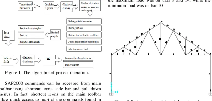
The steps followed in greenhouse design are the selection of load-bearing type and roof coating; determining wind loads; computing purlins based on loads; computing drop bars; determining the loads on framing trusses, determining the stresses occurring on framing truss elements as a result of loads coming to framing truss; dimensioning and checking bottom flanges, upper flanges pillars and diagonals based on the determined stresses; determining the plate thickness and size of the joints; and dimensioning the columns and horizontal braces. Figure 1 presents the algorithm of the operations from the roof to the ground in a sample greenhouse project.
Figure 1. The algorithm of project operations
SAP2000 commands can be accessed from main toolbar using shortcut icons, side bar and pull down menus. In fact, shortcut icons on the main toolbar allow quick access to most of the commands found in pull down menus.
SAP2000 software, which has support for a large number of new, national and international regulations regarding the auto-dimensioning of ferroconcrete and frame elements, presents powerful and fully integrated dimensioning modules. It also provides users with the options for creating, modifying, solving and dimensioning structural models. All of these options are in the same user unit. The program has the capacity to size and optimize initial elements from the same main unit,
Two types of load, one fixed and the other live, have effect in greenhouses. The weights of the elements forming the greenhouse and those of suspended systems make up the fixed loads. Wind load, snow load, hanging plant weight, worker weight, and dynamic seismic loads make up the live loads. The projection in greenhouses begins at the roof as in all structures. After the roofing material is selected, its unit weight is added to the load analysis. The unit weights of other bearing elements defined in initial dimensioning are also added to load analysis. All load and loading positions foreseen in the standards are added to the analysis, calculations are made, the sections determined by preliminary dimensioning are verified, and improper sections are resized. The values used in the sample greenhouse are truss spacing 3 m, truss span 9 m, the number of purlins 9, purlin spacing on horizontal plane 1,13 m, purlin spacing on roof plane 1,25 m, truss mid-height 2.19 m and roof slope 26°.
Various types of roof truss at any span and load position are analyzed in the program. When the program runs, the default truss type is loaded on the screen; however, the program allows the analysis of other truss types as well if input values (truss height and roof slope) are changed. During projection stage, the bars making up the truss members are numbered by considering load effect and ease of installation because truss members can be under different load effects (Figure 2). It was observed in the analysis that
the maximum load was on bars 9 and 14, while the minimum load was on bar 10
Figure 2. System section, joints and element numbers
In the study, bar elements were used for bearing system elements. For the selection of bar elements sections, the SAP2000 profile library was utilized. First, section forces were obtained and sections were verified by following the design steps. Sections and elements were chosen following various controls and calculations to make sure that the choices were economical and safe. The program chooses the lightest sections for the strength of each element so that it can make dimensioning among the user-defined sections. Proved groups of different sections can be specified for different element groups. In addition, different elements can be grouped to be designed as the same section.
Main loads include self-loads, reverse and live loads, snow (without wind), and mass forces of machinery. Additional loads include the effect of wind, earthquake impact, braking forces, horizontal and lateral forces, operational heat effects (in cranes) used in assembly and repair work (based on operation and atmospheric conditions) (TS 648).
First, the solution of roof elements was performed because the projection begins at roof. To do this, the sectional optimization of the bars used in the framing truss elements was performed. For the sectional optimization, an iteration was formed based on some assumptions. Table 1 presents the bar profile sections and the technical features for these sections used in the projection.
The internal forces in the direction of element local axis are given in Table 2. The internal force axial normal force at local axis 1 (P) and internal forces at axes 2 and 3 exert shearing force (V2). V3 values are not presented in the table as they are all zero. Bending moments (M3) were calculated for columns and trusses directly sitting over columns (Anonymous, 2002).
The program has default load combinations supporting the regulations under normal loading conditions related with static fixed load, live load,
91
wind load, earthquake load and/or dynamic response spectrum earthquake load. However, in the projection of the sample greenhouse, main load and main and additional load combinations specified in TS648 were
defined and these combinations were considered in the dimensioning.
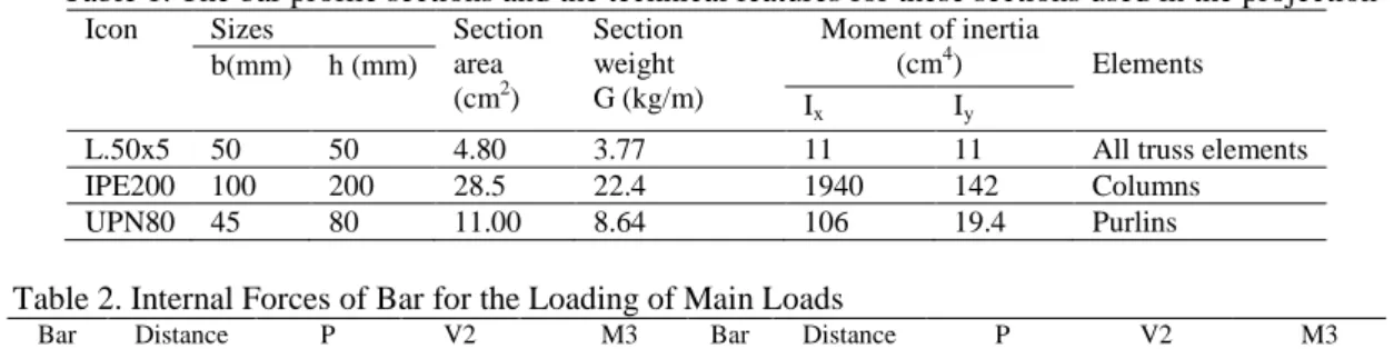
Table 1. The bar profile sections and the technical features for these sections used in the projection
Icon Sizes Section
area (cm2) Section weight G (kg/m) Moment of inertia (cm4) Elements b(mm) h (mm) Ix Iy
L.50x5 50 50 4.80 3.77 11 11 All truss elements
IPE200 100 200 28.5 22.4 1940 142 Columns
UPN80 45 80 11.00 8.64 106 19.4 Purlins
Table 2. Internal Forces of Bar for the Loading of Main Loads
Bar No Distance (m) P (kgf) V2 (kgf) M3 (kg-m) Bar No Distance (m) P (kgf) V2 (kgf) M3 (kg-m) 1 0,00000 -2040,34 -93,19 -157,60 13 0,00000 -55,11 -46,71 -11,11 1 1,25000 -2012,38 -93,19 -41,11 13 0,27375 -57,18 -46,71 1,68 1 2,50000 -1984,42 -93,19 75,38 13 0,54750 -59,24 -46,71 14,46 2 0,00000 -2040,34 93,19 157,60 14 0,00000 -3762,43 -50,55 -35,54 2 1,25000 -2012,38 93,19 41,11 14 0,62558 -3760,37 -46,31 -5,25 2 2,50000 -1984,42 93,19 -75,38 14 1,25115 -3758,31 -42,07 22,40 3 0,00000 3267,76 -60,96 -39,84 15 0,00000 -473,06 -5,66 -3,53 3 0,37500 3267,76 -58,13 -17,51 15 0,54750 -477,19 -5,66 -0,43 3 0,75000 3267,76 -55,30 3,76 15 1,09500 -481,32 -5,66 2,67 3 1,12500 3267,76 -52,47 23,97 16 0,00000 -473,06 5,66 3,53 4 0,00000 3314,47 6,77 9,50 16 0,54750 -477,19 5,66 0,43 4 0,37500 3314,47 9,59 6,43 16 1,09500 -481,32 5,66 -2,67 4 0,75000 3314,47 12,42 2,31 17 0,00000 -3353,27 1,47 6,02 4 1,12500 3314,47 15,25 -2,88 17 0,62558 -3351,21 5,71 3,78 5 0,00000 2428,50 -7,12 -0,65 17 1,25115 -3349,15 9,95 -1,12 5 0,45000 2428,50 -3,73 1,79 18 0,00000 869,87 -3,76 0,27 5 0,90000 2428,50 -0,34 2,71 18 0,99542 863,68 0,48 1,90 5 1,35000 2428,50 3,06 2,10 18 1,99084 857,49 4,72 -0,69 5 1,80000 2428,50 6,45 -4,263E-02 19 0,00000 -878,79 -2,65 0,11 5 2,25000 2428,50 9,84 -3,71 19 0,99542 -872,60 1,59 0,64 6 0,00000 2428,50 -7,12 -0,65 19 1,99084 -866,41 5,83 -3,05 6 0,45000 2428,50 -3,73 1,79 20 0,00000 -878,79 -2,65 0,11 6 0,90000 2428,50 -0,34 2,71 20 0,99542 -872,60 1,59 0,64 6 1,35000 2428,50 3,06 2,10 20 1,99084 -866,41 5,83 -3,05 6 1,80000 2428,50 6,45 -4,263E-02 21 0,00000 869,87 -3,76 0,27 6 2,25000 2428,50 9,84 -3,71 21 0,99542 863,68 0,48 1,90 7 0,00000 3314,47 6,77 9,50 21 1,99084 857,49 4,72 -0,69 7 0,37500 3314,47 9,59 6,43 22 0,00000 -3353,27 1,47 6,02 7 0,75000 3314,47 12,42 2,31 22 0,62558 -3351,21 5,71 3,78 7 1,12500 3314,47 15,25 -2,88 22 1,25115 -3349,15 9,95 -1,12 8 0,00000 3267,76 -60,96 -39,84 23 0,00000 1472,74 2,498E-16 7,372E-16 8 0,37500 3267,76 -58,13 -17,51 23 1,09500 1481,00 2,498E-16 4,637E-16 8 0,75000 3267,76 -55,30 3,76 23 2,19000 1489,25 2,498E-16 1,902E-16 8 1,12500 3267,76 -52,47 23,97 24 0,00000 -3348,38 -1,42 2,41 9 0,00000 -3762,43 -50,55 -35,54 24 0,62558 -3346,32 2,82 1,97 9 0,62558 -3760,37 -46,31 -5,25 24 1,25115 -3344,26 7,06 -1,12 9 1,25115 -3758,31 -42,07 22,40 25 0,00000 -3348,38 -1,42 2,41 10 0,00000 -55,11 46,71 11,11 25 0,62558 -3346,32 2,82 1,97 10 0,27375 -57,18 46,71 -1,68 25 1,25115 -3344,26 7,06 -1,12 10 0,54750 -59,24 46,71 -14,46 26 0,00000 -2254,19 0,87 2,21 11 0,00000 -440,34 -9,35 -1,12 26 0,62558 -2252,13 5,11 0,34 11 0,62558 -438,28 -5,11 3,40 26 1,25115 -2250,06 9,35 -4,19 11 1,25115 -436,22 -0,87 5,27 27 0,00000 -2254,19 0,87 2,21 12 0,00000 -440,34 -9,35 -1,12 27 0,62558 -2252,13 5,11 0,34 12 0,62558 -438,28 -5,11 3,40 27 1,25115 -2250,06 9,35 -4,19 12 1,25115 -436,22 -0,87 5,27
The default load combinations assume that all static load states defined as a constant load are summed. Similarly, the states defined as live load are also assumed to be summed. However, it is assumed that wind, earthquake or response spectrum cannot be summed with each other and that they will form multi-lateral load combinations. In addition, earthquake and wind load states form separate load combinations when they are reversed (positive or negative). If these states are incorrect, the user should provide correct dimensioning combinations. Figure 3 presents the calculation of wind loads.
Figure 3. The calculation of wind loads
The program also provides an interactive environment, where the user can examine the stress status, for example, make appropriate changes such as the reorganization of section sizes, and develop the dimensioning without re-analyzing the structure. Detailed dimensioning options can be loaded onto the screen with just one click on an element. All stress values allowable for axial bending and shear effects and design capacity values are computed by the program. Boring calculations regarding effective length multipliers for the columns in moment resisting frame type structures are automatically performed in the program algorithm. Stress control axis is given in a colored distribution table, where the bar sections are also displayed. While the bars marked in red shows they are forced over their capacity, those not forced over their capacity are marked in blue or green. Stress control screen is given in Figure 4. Main load forces in deflection verification are given in Figure 8.
Figure 4. Stress control and bar sections screen
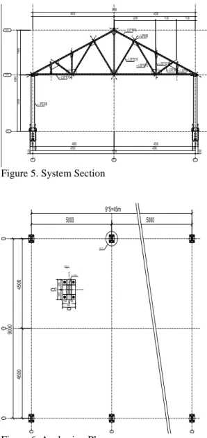
The presentation of the results is clear and specific. The output data are in a form that gives opportunity to engineers to take measures in case an element exceeds stress limits. The dimensioning data produced by the program are saved so that the results can easily be implemented. The analysis results can easily be obtained. The anchoring plan and system section of the sample greenhouse are presented in Figure 5 and Figure 6.
Figure 5. System Section
Figure 6. Anchoring Plan
4. CONCLUSION
This study aimed to achieve more accurate results in less time by incorporating computer use into the process of greenhouse design. The use of package software in the projection of greenhouses, which entails handling various complex calculations and equations, allows obtaining accurate and fast results. With the SAP2000 software, fixed and live loads on the greenhouse are determined and the static analysis
93
of the framing truss system is done by using nodal point method. For the optimization of the system, the boundary conditions are considered for the different sizes of the profile elements, and therefore material losses are minimized.
Although the computer programs used in the projection facilitates the process to a great extent, such programs should be used by experienced engineers who know the program features well and have enough knowledge about calculation methods. The selection and construction of the project should be controlled by related engineers in line with the related regulations and standards. The practitioners should be able to make necessary controls over the errors stemming from the program or the user. The most important point to consider in greenhouse projection is to enter correct data into the program, so that the correct solution is reached. It is obvious that entering correct data will ensure accurate results and save time. It is important to establish organizations which will supply the greenhouse owners with technical information during the design and establishment of greenhouses. 5. REFERENCES
Anonymous, 1997. Design loads for buildings TS 498, Turkish Standards Institution. Ankara, p 24.
Anonymous, 2003. Greenhouses: Design and Construction-Part 1: Commercial Production Greenhouses, TS EN 13031-1, Turkish Standards Institution. Ankara, p 88. Anonymous, 2004. SAP2000 v8 Educational, Computers
and Structures, Inc. Berkeley, Cal.
Anonymous, 2002. Steel Sizing Guide, Software Series for Analyzing the Structures with Finite Elements, Computers & Engineering 1992-2002, www.comp-engineering.com.
Baytorun A.N. 1995. Greenhouses. CU. Agricultural Faculty General Pub. No: 110. Lecture Note No: 29. p. 406. Adana.
Kocabaş, S. 2005. Thesis Analysis and Design of Steel Constructions with the Aid of SAP 2000. MSc Thesis. Department of Civil Engineering, Institute of Natural and Applied Science University of Cukurova p.120 . Adana.
Tunaboyu, O. 2007. Computer Aided Structural Design, Department of Civil Engineering, Institute of Natural and applied Science University of Osmangazi, p.178, Eskisehir.
Yakut, M. 2007. Usage of Information Technology to Analyze and Design of Steel Truss Structures. MSc Thesis. Department of Civil Engineering. Institute of Natural and Applied Science University of Ondokuzmayis. 94 s, Samsun.
Yuksel A.N. 2004. Greenhouse Construction Technique. Hasad Publishing Ltd. Co., Istanbul, 287p.