978-1-4799-1622-1/14/$31.00 ©2014 IEEE
Model-Based GN&C Simulation and Flight Software
Development for Orion Missions beyond LEO
Ryan Odegard Draper Laboratory 17629 El Camino Real Houston, TX 77578 [email protected] Zoran Milenkovic Draper Laboratory 1555 Wilson Blvd, Suite 501 Arlington, VA 22209 [email protected] Joel Henry
NASA Johnson Space Center 2101 NASA Parkway
Houston, TX 77058 [email protected]
Michael Buttacoli NASA Johnson Space Center
2101 NASA Parkway Houston, TX 77058 [email protected]
Abstract—For Orion missions beyond low Earth orbit (LEO), the Guidance, Navigation, and Control (GN&C) system is being developed using a model-based approach for simulation and flight software. Lessons learned from the development of GN&C algorithms and flight software for the Orion Exploration Flight Test One (EFT-1) vehicle have been applied to the development of further capabilities for Orion GN&C beyond EFT-1. Continuing the use of a Model-Based Development (MBD) approach with the Matlab®/Simulink® tool suite, the process for GN&C development and analysis has been largely improved. Furthermore, a model-based simulation environment in Simulink, rather than an external C-based simulation, greatly eases the process for development of flight algorithms. The benefits seen by employing lessons learned from EFT-1 are described, as well as the approach for implementing additional MBD techniques. Also detailed are the key enablers for improvements to the MBD process, including enhanced configuration management techniques for model-based software systems, automated code and artifact generation, and automated testing and integration.
T
ABLE OFC
ONTENTS1.
I
NTRODUCTION... 1
2.
S
IMULINK ON-
ORBIT SIMULATION... 2
3.
S
IMULINK VARIANTS... 3
4.
F
LIGHTS
OFTWAREM
ODELING... 4
5.
C
OMPATIBILITYW
ITHE
XTERNALS
IMS... 5
6.
C
ONFIGURATION MANAGEMENT... 6
7.
M
ODEL MERGING... 7
8.
S
IMULATIONV
ALIDATION,
V
ERIFICATION,
ANDD
OCUMENTATION... 8
9.
A
UTOMATEDB
UILD ANDT
ESTS
ERVICES... 9
10.
A
UTOCODE... 9
11.
M
ETRICS... 10
12.
S
UMMARY... 11
A
CKNOWLEDGMENTS... 12
R
EFERENCES... 12
B
IOGRAPHY... 13
1.
I
NTRODUCTIONThe Orion spacecraft is being developed by NASA to take humans back to deep space. The first test mission, EFT-1, will demonstrate many capabilities for extending the human presence in space beyond LEO. For the Orion GN&C flight software (FSW), which is responsible for navigating, guiding, and controlling the vehicle, a model-based development process has been implemented. Advantages of MBD in human spaceflight algorithm development on Orion have been previously described [1, 2]. Specifically, distinct benefits from MBD have been realized to date on Orion: removal of the steps of converting GN&C algorithmic pseudo-code documentation to flight software, increases in the amount of time spent exercising flight code, improvements in the processes for producing algorithm documentation and reviewing algorithm functionality, implementation of automated checking of software standards, and development of an automated testing framework and report generation.
As part of that EFT-1 FSW development process, several challenges and areas of improvement were identified. These included configuration management difficulties, code integration and graphical merging shortcomings, development complexities related to the simulation environment, slow simulation execution speed, efficiency of generated code, and long model build times. To address the challenges and lessons learned from EFT-1, a number of improvements have been implemented. The first has been to develop a medium fidelity, model-based, simulated 6-degree-of-freedom (DOF) environment using Simulink [3] in which to exercise flight algorithms. The past use of C-based simulation environments required additional overhead and complicated interfaces to the Simulink environment. The Simulink simulation is also tailored to on-orbit flight regimes, which allows faster execution speeds. Another advantage has been the use of Simulink model variants, which improves build time and allows quickly exercising different functionality without modifying the models. A collection of process improvements has been implemented to address the challenges of configuration management and https://ntrs.nasa.gov/search.jsp?R=20140003581 2019-08-29T14:23:09+00:00Z
c h d N v v r w s a s a im a O r g P h S im m T d th C F in C d C C c C o C f C t c code developm have served development a NASA reposito various team m version control revision contro work-flow and scripts used f automation cap software develo an automated b mprovements and continuous Other improve request integr generation, bui Previous challe have been alle Simulink mod mprovements members. The following during EFT-1 his paper. Challenge: Pr FSW can be nterfaces betw Challenge: En dispersed teams Challenge: Spe Challenge: Im capability for S Challenge: Eas of development Challenge: Sp for individual d Challenge: Ma estable versi concurrently w ment processes as enablers approach for ory has proven members. The l tool has dem ol system tool removed depe for EFT-1 d pabilities have
opment proces build and test s over EFT-1 i sly test the m ed automation ration, regress ild artifact gen enges in perfor eviated by the del merging for communi is a summa software deve rovide an env developed q ween C and Sim hance collabor s operating on eed up model d mplement a Simulink mode se the burden o t at once, leadi eed up and au developers. aintain and man ion of the ith model deve
s. The proces for the S GN&C. Cen n beneficial an e use of the g monstrated grea l. It has also endencies on a evelopment. been utilized ss. Central to erver, which h in the ability odels and the n processes sion and uni
eration, and m rming three-wa e use of recen tools, as w icating conflic ry of challen elopment that vironment whe quickly and mulink. ration between different secur development. usable grap ls. of integrating m ing to long inte utomate testing nage a workin auto-generate elopment. F ss improvemen Simulink mod ntralization to nd accessible it [4] distribut at flexibility as o simplified t a host of custo A number to speed up t this is the use has enabled ma to automatica generated cod include chan it testing, co metrics collectio ay model merg nt capabilities well as proce cts among tea nges encounter are addressed ere model-bas without TCP/ n geographical re networks. phical mergi multiple branch egration cycles g and integrati ng, compiled, a ed FSW co Figure 1. Top 2 nts del a by ted s a the om of the of any ally de. nge ode on. ges in ess am red in sed /IP ly-ing hes . ion and ode The pri process build environ approac fidelity prelimi simulat adequa running multipl connec simulat on both minutes both th require program wherea require better u share opportu commo the rev validati not nee simulat Overall the co streaml and exe The Sim (FLight collecti (Rapid Simula that co flight s logging simulat -level simulati
2.
S
IMULIN imary improve s for the Oriona medium nment using Si
ch for the EFT y, C-based simu inary design tion allows fa ate accuracy fo g the C-based le processes ctions, which ad tion execution h the simulatio s to execute p he C-based sim es developers mming langua as a Simulink ement to a larg understand eac developer re unities for reu on look and fee view and cod
ion process. A ed significant tion tools prio l, having the s omplexity of lining and sim ecution process mulink-based t Algorithm ion of flight Algorithm ation). Figure ontains the FL software mod g block for re tion run. ion model. NK ON
-
ORBIT ement in the m n GN&C FSW fidelity, m imulink. This T-1 GN&C dev ulations. For review (PDR faster developm or the maturity d simulation communicatin dds complexity process. The on side and the prior to each s mulation and ths to be p ages for devel k only envir ge degree. Thi ch other’s work
esources if use across the el to the subsy de audit steps Also, engineer training on i or to starting simulation mod interfacing w mplifying the ses. simulation has Simulation E software mod m Matlab/S 1 shows the to LASHE simula els. Each ha ecording outpu T SIMULATIO model-based de development h model-based differs from th velopment that development p R), the mediu ment while m y required. Fu with Simulin ng via TCP/ y and I/O overh ere are initializ
e Simulink sid simulation run. he Simulink m proficient in lopment and d ronment allev is allows for d k, provides the needed, fost e team, and p ystem design th in the verific rs new to the initialization s algorithm dev dels in Simulin with the FSW simulation in s been dubbed Environment), dels is called Simulink E op level Simu ation and the as a correspon ut variables to ON evelopment has been to simulation he previous t used high prior to the um fidelity maintaining urthermore, nk requires /IP socket head to the zation steps de that take . Running models also multiple debugging, viates that designers to e ability to ters more provides a hat benefits cation and project do scripts and velopment. nk reduces W models, nitialization d FLASHE and the RAMSES Engineering link model RAMSES nding data o file for a
F O m v a e a in o B a p m to s T O M R A d v v T S a ( m d lo a C m w F ta w A r s m c r D L G c f S a a s N o FLASHE inclu Orion vehicle a models to rep vehicle forces a atmospheric an effects for quie a variety of o ntegration, in ode45, etc., wi Because the RA as a fixed ra processor, a c method is impl o be sufficien speed.
There are also Orion vehicle u Measurement Receivers (GP Altimeters (BA done on EFT-vehicle, which vehicle state. The effector mo System (RCS) and a main e (TVC). The Si models reuse th different mode ocations, direc also reused be Crew Module models represe when Orion exe Finally, FLASH arget vehicle with another sp All of the mo reference para structure organ model hierarch can be chan recompilation o Data Logging Logging of dat GN&C develop capabilities in for EFT-1. Thi Simulink mod advantages are algorithmic mo signals are logg Native Simulin options. For lo
udes a number and its environ present the ef and torques fro nd aerodynam escent flight ou options for pe cluding such ith both fixed-AMSES FSW ate, as they w custom, 4th o lemented in th nt in terms of o models that used for naviga Units (IMUs) SRs), Star Tr AROs). Mostl 1, these mode the navigation odels in FLAS thruster mode engine model imulink implem he same mode l reference par ctions, and ma tween the Ori (CM) models ent the expect
ecutes large ma HE has also b model to simu pacecraft. odel reference ameters that a nized hierarchi hy. The param
nged betwee of the models.
ta in Simulink pment. The lac
Simulink led t is model can be del output da
e that it does odels themselv ged, and it wri nk capabilities ong simulation r of models th nment. These i ffects of grav om thruster an mic effects, an utside LEO. S erforming diffe solvers as o step and varia models are req would on the order Runge-K he vehicle dyn f accuracy an represent the ation purposes ), Global Pos rackers (STs), ly inherited fro els emulate the n software use SHE include a R el, Auxiliary ( with Thrust mentation of th l reference blo rameters that s agnitudes. Th ion Service M . The main e ted behavior a agnitude burns been configure ulate rendezvo es in FLASH are collected ically that cor eters as passed en runs wit
has been a cha ck of data conf to a custom fi e reconfigured ata to file. s not require ves in order to
ites data to disk do not suppor n runs with ma hat represent t include dynam vitational forc nd engine firing d solar pressu imulink provid erential equati ode15s, ode23 able-step option quired to execu e vehicle targ Kutta integrati
amics and fou nd computation e sensors on t s, such as Inert sitioning Syste and Baromet om developme e sensors on t es to estimate t Reaction Contr (Aux) jet mod
Vector Contr he RCS and A ock by passing specify the thru he RCS model Module (SM) a engine and TV and performan s. ed with a simp ous and docki
E utilize mod in a workspa rresponds to t d into the mod
thout requiri
allenge for Ori figurable loggi le-writing mod d to allow loggi The two ma changes to t o alter what da k during the ru rt either of the any models, it the ics es, gs, ure des ion tb, ns. ute get ion und nal the tial em tric ent the the rol del, rol Aux in ust is and VC nce ple ing del ace the els ing ion ing del ing ain the ata un. ese t is critical because large a more r alternat time re With re decided and de utilizin on rege logging FLASH the des record within custom rebuild can be support Figure o One ke model of mod 2009A, reconfi the Ori switch interfac implem model effect), By se conditio variant to be able t e there is a s amounts of dat recent FLASH te approach is equired to upd ecent support f d to focus less evelop a fast, r ng native Simu eneration of a g specification HE and RAMS sired rates are files, and the seconds. This m recording m
d. The data rec either leaf-le t arrays of bus e 2. Automati on configurab
3.
S
I ey feature of development f del reference va , model varian iguring a mode ion GN&C pro between mo ces. For exam ments a point-m that accounts , and a third im etting variable onal setting of gets executed to configure significant imp ta are logged HE and RAM s taken primardate the custo for 64-bit MAT on writing da reconfigurable ulink capabiliti Simulink mod ns are set pro SES outputs.
e set in one o e logging mo s is an improv model, which t cord files cont evel elements signals, as of M
ically generate ble signals and
IMULINK VA Simulink that for FLASHE a ariants. Introd nts provide a el with a differ oject, model va odels without mple, one var mass, a secon s for the obla mplements high es in the M f the Simulink . which data a pact on run sp
during the run MSES develop rily due to the om data loggi TLAB installati ata to disk durin e data logging es. This appr del in which th ogrammatically The variables or more text-b odel can be r vement over th takes several m
taining the sig or bus signal MATLAB 2013
ed logging mo d recording ra
ARIANTS t has been lev and RAMSES duced in MATL data-driven m rent implement
ariants are use t modifying riant of a grav nd implements ateness of the her-order grav MATLAB wor k block determ are logged, peed when n. For the pment, an e length of ing model. ons, it was ng the run, capability oach relies e Simulink y for both to log and based data regenerated he previous minutes to gnals to log s, and can a. odel based ates. veraged in is the use LAB version method for tation. For ed to easily blocks or vity model s a gravity Earth (J2 vity effects. rkspace, a ines which
T to m b u m b d s W im “ b d A a in im th A a o f M O in p o it S p p m o a m m f la m b m m b T f lo g d The primary w o create empt models. This being compiled use of this conc models. Instea behaves accor dynamics, the state of the veh When the deta
mportant for “perfect navig building (and r development. Another varian alternatives f nformation. mplementation he simulation, A second varia any run-time offers flexibili fidelity models MATLAB works On the RAMS nclude model phases of fligh of all the cod
terations of d Simulink archit phases ranging proved challen management an on-orbit simula algorithms des model variants moon do not r for ascent abor
anding algori maintained an between those model variants maintenance p benefit.
4.
F
L The GN&C fli functional “domogic and code. given functiona domains shown
ay in which m ty “stub” refer
allows the ex d and run for a cept in FLASH ad of represen ding to the e stub models m hicle, as calcu ails of the perf a certain set gation” setup ebuilding) the nt implementat for modeling The first n of the SPICE for establishin ant uses a tabl
dependence o ity in running s with just the space.
SES side, mod code in the p ht, but not requ
de for simula development p tecture for inte from ascent to nging from t nd build and ex ations carried signed for hig s, simulations
equire the incl rt logic and co ithms. Yet nd managed e models are un s. From a fl perspective, thi LIGHT
S
OFTW ight software mains” that co . The algorithm al domain, so e n in Table 1. odel variants h rence blocks xclusion of a s a certain simul HE is the creati nting how theenvironmental merely pass th ulated in the dy formance of th of GN&C an saves the de complex senso tion in FLASH g the plane variant use E system [5], c ng planetary bo le lookup routi n the SPICE g lower over e change of a del variants ha project reposito uire compilatio ation runs. D prior to mod egrating GN&C o on-orbit to e the perspectiv xecution speed the overhead ghly dynamic involving fli lusion of mod ontrol, nor ent
the overall easily because naltered with t light software is has proven WARE
M
ODE is broken up mpartmentaliz ms for GN&C each is groupehave been used for some of t set of code fro lation. The ma on of stub sens sensor hardwa conditions a hrough the “tru ynamics mode he sensors is n nalysis, then th veloper time or models duri HE has been tw tary epheme es a MATLA computed duri ody ephemerid ine that remov
libraries. Th rhead or high a variable in t
ave been used ory for all Ori on and executi During previo del variants, t C code for flig entry and landi ves of interfa . Even quiesce d of atmosphe
periods. W ghts around t dels that are bu try, descent, a
architecture e the interfac the use of “stu integration a n to be of gre ELING into a series ze portions of t C are specific to ed into one of t 4 d is the om ain sor are and ue” els. not his in ing wo eris AB ing es. ves his her the to ion ion ous the ght ing ace ent eric With the uilt and is ces ub” and eat of the o a the Ta Flig Doma * NVR planned The fl develop CNP do of the for the As sho RAMS Figure As me variants Simulin specific on-goin explora primari of the algorith “orbit” domain variant, run in t Figur able 1. List of ght Software in Abbreviati CNC CNL CNE CNP CNS GDA GDE GDO GMP NVA NVE NVR* is not implem d for near term O
light algorithm ped in Simulin omains, which domains are in development own in Figure ES consists of e 3. RAMSES entioned in the s in the mode nk has allowe c simulation p ng work for ation of the ily on-orbit GN development hms related to model varian ns shown in F , there are 73 the simulation. re 4. RAMSE the o GN&C Flight ion Crew M Launch A Engine C Propulsi Service M Ascent G Entry Gu Orbit Gu GN&C M Absolute Ephemer Relative mented as rendez Orion missions. ms for each nk with the ex h are written d ntegrated into and testing of 3, the “integr f all of these do S "Integrated" the GN&C FS e previous sec eling of the G ed greater fine erformance. S r Orion is Moon and b N&C function and analysis o atmospheric nt is establish Figure 4. By fewer models ES "Orbit" va on-orbit GN& t Software Do Description odule Controls Abort System Controls ion System Con
Module Contro Guidance uidance uidance Mass Propertie e Navigation ris Navigation Navigation
zvous and dock
of these do xception of the directly in C++ the RAMSES f those flight a rated” model omains. " variant inclu SW.
ction, the use GN&C flight s e-tuning of fli Specifically, m geared towar beyond, which nality. As a re s is independe c flight. The hed, which in y using the or that need to b ariant inclusiv &C FSW. omains n s Controls ntrols ols es
king are not
omains are e CNE and +. The rest S modeling algorithms. variant for usive of all e of model software in ight-phase-much of the rd further h includes esult, much ent of the erefore, an ncludes the rbit model e built and e of only
I F p d m n 6 s “ o n p n d a T th th F p p S p tr n in c s s F 1 s P P N R S F S R In addition to FSW, there is perfect navigat describing the F models, perfect navigation fligh 60% of the tota sent to the gu “truth” state, ra on-board from navigation sen provide time navigation, but development algorithms. There are actua
hat can be exe he perfect nav FSW, but to ru parallel. Th performance bu Secondly, a st provides a me rue state to re navigation fligh ncrementally controls analys sensors or fligh summarizes FLASHE/RAM 168 fewer mo simulation. Table 2. S Nav Variant Name PerfectNav PerfectNav_ NVAProcessing RealNav StochasticNav Figure 5 show Simulink for c RAMSES. the “integrate also a big ad tion. As men FLASHE varia t navigation ca ht software, w al GN&C code idance and co ather than the m incorporatin nsors. Not o savings when t perfect navig
and analysis
ally two additio ercised in FLA vigation state un the sensors his allows as ut without effe tochastic navig eans of non-de epresent the ty ht software. Th higher level is, without the ht software mo the naviga MSES. By usin odels that need
Summary of n Active Nav Pathway (to G&C) P (f Perfect n/ Perfect N NVA Pe Stochastic Pe ws the switch configuring the d” and “orbit” dvantage in be ntioned in the
ants for stubbin an also be use which comprise e. In effect, the ontrols domain state that wou ng measurem only does pe n compared t ation capabilit of guidanc onal navigation ASHE/RAMSE in the guidan s and navigatio ssessment of ct on the contr gation variant eterministically ype of estimat his implementa of fidelity fo e need to includ
dels in the sim ation varian ng perfect navi d to be built avigation mod Passive Nav Pathway for telem) Sens Mod Used /a Off VA On erfect On erfect Off hing logic im e perfect navig ” variants of t eing able to r previous secti ng out the sens ed to exclude t es approximate e navigation sta ns represents t uld be estimat ments from t erfect navigati to full absolu ty is essential f ce and contr n-related varian S. One is to u nce and contro on algorithms the navigati rol of the vehic is setup, whi y perturbing t tion done by t ation provides or guidance a de the navigati mulation. Table nts used igation, there a and run in t del variants. sor dels d? Descriptio Perfect Nav NVA and sensors running for telemetry NVA runnin and used by G&C Truth state perturbed mplementation gation variant the run ion sor the ely ate the ted the ion ute for rol nts use ols in ion cle. ich the the an and ion e 2 in are the on ng in in The oth softwar the com sequenc Within softwar comma triggeri appropr Becaus has bee base fo there implem stressin Anothe model-variants known (PSAM hierarch division orbit, a which on-orbi Within within burn se the bur a trim b For eac that con the con thresho activity sets of Tool, a mission the mai of a com
5.
While numero orbit al for the Figure 5. P her benefit of re models into mmon GN&C cing and exec the GN&C re domain live and handler sof ing and config riate time, ba se this software en crucial to be or the integrate were sepa mentations for ng on the maint er set of comm based design s is the tool s as the Phase M) Tool [6]. hical portions ns of the miss and entry. Thecomprise vehi it burn, or co the GN&C su a segment that egment, the GN rn attitude, per burn if necessa ch activity, the ntrol which al nfiguration pa olds, limits, de y. The GN&C f data that are and loaded in n. For an inte intenance of th mmon code ba
C
OMPATIBI the FLASHE ous benefits in lgorithms, mor e Exploration Perfect naviga being able to o the same RAM C executive socution of all C Command
es the executiv ftware. This d guring the appr ased on data-c e executes duri e able to maint ed set of FSW arate reposi different flig tenance of the mon code that n approach u set that is used es, Segments, The acronym
of the missio ion are the ph e phases are su icle-level goals oasting in a ubsystem ther t are referred t N&C activities rforming a mai
ary, and assum e GN&C doma lgorithms are e arameters for adbands, etc., C activities, mo configured wi nto GCI for e
egrated set of he PSAM Tool ase as does the
ILITY
W
ITH E simulation e n doing rapid re formal analy Mission-1 (E ation switching integrate all o MSES architec oftware that co of the GN&C Interface (G ve sequencer a domain is resp ropriate algorit configurable i ing all phases tain a common W code. If, alt itories or ght phases, it common GCI has benefitted using Simulin d to data-confi Activities, a m PSAM ref on timeline. ases, such as a ubdivided into s, such as perf particular con re are specific to as activities s include mane in engine burn, ming a post-bur ains are in spec executing. Fu the algorithm are specified f odes, and para ith the aid of xecution throuRAMSES FSW enjoys the sam
GCI domain.
E
XTERNAL environment h d FSW develo ysis and testing EM-1) to the g. f the flight cture is for ontrols the C domains. GCI) flight and GN&C onsible for thms at the input files. of flight, it n GCI code ternatively, Simulink would be software. d from the nk model figure GCI, and Modes fers to the The major ascent, on-o segments, forming an nfiguration. objectives . Within a euvering to , executing rn attitude. cific modes urthermore, ms, such as for a given ameters are the PSAM ughout the W models, me benefitsS
IMS has shown opment for g after PDR moon will6 require other higher fidelity C-based simulations. For this reason, and because FLASHE is not intended to support ascent or descent and landing phases of flight, an interface to NASA’s Trick Simulation Environment [7] has been updated to work with the 2013a version of MATLAB. Data being passed between the Trick simulation and the FSW in Simulink are exchanged via TCP/IP socket connections using custom s-functions, as was done for EFT-1.
There are two main aspects of the interface between Trick and RAMSES. The first is that the input/output data must be maintained, and can then support multiple other Trick-based simulations. There are likely two Trick-Trick-based simulations that will require interfacing with the GN&C FSW in RAMSES, so the development in Simulink and with FLASHE will ensure the Trick interface is maintained. The current FLASHE regression testing includes a check that these interfaces do not break as development progresses. The second main aspect of the RAMSES interface to the Trick simulations is that the FSW functionality remains consistent across simulation environments. The FLASHE regression testing is also exercising a subset of the functionality that is unique to the Trick simulation, in that it is part of an ascent profile which is not the primary role of FLASHE. Thus, the GN&C FSW, as developed in RAMSES, is maintained for operation in both Simulink- and Trick-based simulation environments.
6.
C
ONFIGURATION MANAGEMENTOne of the biggest challenges in the Orion GN&C FSW development, both before PDR and leading up to the EFT-1 flight test, was configuration management. While MBD affords many benefits over the course of a project, having a large, geographically dispersed team across many organizations makes working with graphical models particularly challenging. The first hurdle in working with many organizations is dealing with separate information technology (IT) and security requirements; finding a method in which all team members can share information has never been a trivial problem. Secondly, the set of tools for managing the work of many team members must be both robust and easy to use in order to facilitate deploying flight software. While solutions were found for both of these problems for EFT-1, they were not ideal and recent work has largely improved these aspects of the GN&C development process.
Members of the Mathworks team have described configuration management techniques in the context of Simulink model development [8]. The Orion GN&C team, however, has learned two important lessons for successfully carrying out Simulink model development with dispersed organizations: establish easy access to a configuration controlled repository and utilize tools that ease distributed development.
Simulation model and flight software development for EM-1 has utilized servers at NASA’s Johnson Space Center (JSC) to centralize code and model repositories. While organizations often limit internal network access due to security and intellectual property reasons, the roles of Orion contractors with NASA already include the contractual agreements required for a collaborative work environment on JSC servers. As a result, there have been far fewer, and more minor, issues related to GN&C developers having access to the JSC repositories.
The configuration management tool that greatly aids the Orion GN&C configuration control process has been git, an open-source, distributed revision control system. Git has been successfully used for large projects such as the Linux kernel and has a large user base. Because git is a distributed source code management system, there is no dependency upon a server connection to manage file revisions. Furthermore, because each developer has a complete history of a repository locally, actions in git are faster than a centralized system. In fact, compared to the EFT-1 code management database, git is one to two orders of magnitude faster on common operations such as creating a new repository and checking the status of file modifications. With other revision control tools used in the past, there was a need to develop a set of custom scripts that managed a “view” of the source code. These scripts provided two main functions: enabling interfacing with different simulation environments, and segregating the source code under configuration management from the generated artifacts. When working in a view, the custom scripts managed the interactions between the simulation and the RAMSES models in Simulink to simulate a mission run. Also, the execution of Simulink models involves the generation of executable artifacts (i.e. .mex* files). When present in a configuration controlled area, these mex files are potentially a hassle to separate from the maintenance of the source code. The use of git makes this problem obsolete with the ability to ignore certain files or types of files. Therefore the dependence on custom scripts and “views” were completed eliminated by using git.
In addition, git is particularly adept at non-linear development, where branches and merges are common, easy, and fast. This has made collaboration for FLASHE and RAMSES development much easier than in the past. Previously, exchanging source code between organizations was done via one of two inconvenient methods: post source file(s) to a secure website where it could be downloaded by another developer, or wait for the periodic synchronization of databases between organizations, which was as infrequently as once per week. With access via simple ssh connections to the common JSC servers and with git merging capabilities, exchanging and sharing work is significantly more efficient.
Another improvement in the FLASHE/RAMSES development for EM-1 has been the code integration process. The two process approaches used previously were
1) monthly submissions of code changes to an integration team, and 2) a small team responsible for all changes directly incorporated into the primary FSW code database. The first approach was used early on in the project when there were more GN&C developers doing parallel development without efficient means of recombining the work. The monthly integration process was a large and challenging effort for reasons including limited tools for merging distributed changes, long integration periods, and simultaneous code changes to graphical models that were difficult to merge. It was not uncommon for the process of integrating all of the code changes to take up to a month, which left essentially no time for developers to include their new updates into the latest baseline. This process was inefficient for all involved. When the EFT-1 flight test mission was established, the GN&C team moved into more of a production mode with a limited team involved in making direct changes to the GN&C models and code. Members of the small team could see updates immediately, but the larger community was required to wait for baselines, which were generally months apart. For developers who were not on the small team, their work was done on top of a baseline release. That work was then sent to a team member who could integrate it into the configuration management tool, but those steps were accomplished via email or posting to a common area, completely outside of the CM tool. If any other changes had occurred in parallel, those had to be manually merged or reapplied. None of these interactions utilized features which configuration management tools are intended to provide.
The process that has been implemented more recently with FLASHE/RAMSES development has been an automated continuous integration process. Scripts running in the JSC lab monitor for requests for integration from GN&C developers. This request comes via a web-based issue submittal page where the developer specifies the location of his or her repository as well as the git branch containing the work. Then a series of regression tests are automatically started. If the developer’s work merges properly and passes the regression tests, then it is automatically merged into the “central” repository for others to retrieve. If the merge with the developer’s branch or the regression tests fail, logs are created and made available on the issue page for review. The automatic and continuous nature of the integration process takes advantage of the best aspects of the previous integration processes, while also adding automation that saves a lot of time. Like the process used for the small production team on EFT-1, the developer is responsible for keeping up to date with progress and work being integrated into the central repository. For example, if a developer has not merged the latest work into his or her branch prior to requesting integration, it is possible that the merge will contain conflicts. Instead of the responsibility for cleaning up the merge conflicts being the job of an integrator, it is the responsibility of the developer to properly merge in the latest from the central repository to ensure the automatic integration process runs to completion. Because integration
takes place continuously, a developer can pull the latest as often as multiple times per day, with low overhead, in order to incorporate small changes more frequently to make tasks that take a long time to complete easier to manage. Another improvement over past processes is that the regression testing is completely automated, as long as the data used to verify the regression tests do not change. For the production team on EFT-1, it was important that changes were not introduced that inadvertently caused simulation runs and tests to fail. At times this could be a burden because of the amount of time it took to build and execute all the models and tests. With an automated process, it is simpler and faster for a developer to rely on an automated regression and verification process to take the time to build and execute the models, while the developer’s time and computer resources can be freed up for other productive uses.
7.
M
ODEL MERGINGAnother common challenge with model-based development, specifically with graphical models, is model merging. For ASCII, text-based files, there is a long history, familiarity, and simplicity with merging multiple changes to the same file. Finding the differences in one or more lines of source code is relatively straightforward, so merging can be automatic when there are no conflicts between the changes, or can be compared side-by-side when the changes conflict with one another. Although the .mdl format for Simulink models are text-based, it is not straight-forward to merge these text files and still have a functioning graphical model in Simulink. As a result, model differencing and merging requires being able to view the Simulink models themselves, not the text files.
In the past, the Orion GN&C team experimented with third-party differencing and merging tools called SimDiff and SimMerge by Ensoft [9]. Recent releases of MATLAB have introduced tools for merging Simulink models. The Simulink tools are capable of finding and merging small to medium sized differences in models but cannot automatically track large changes, which is true even of text-based merging. For Orion, the GN&C flight software team has not required specialized licenses for model development; only MATLAB, Simulink, and Stateflow are needed. The Simulink merging tool, however, is only available with the Simulink Report Generator toolbox, so license costs are a deterrent and hindrance for many GN&C developers. As a result of this limitation, the GN&C team has customized the interaction between git and Simulink .mdl files, and also developed a process that facilitates conflict communication between model developers.
When conflicts occur when merging text files in git, the syntax convention of “<<<<<<” and “>>>>>>” is used to indicate modifications made by the developer doing the merge, the work being merged into, and the common ancestor. For Simulink .mdl files, these modifications inserted by git prevent an executable model from being
8 opened in Simulink. A customization of the attributes of git has been implemented to instead create three separate .mdl file instances: “theirs,” “mine,” and “ancestor.” With this specific handling of merge conflicts of .mdl files, the Simulink model differences can be viewed either side by side, or with other model merging tools.
There are some very beneficial aspects of git being a distributed revision control system whose utilities have been described in previous sections. One challenge in Simulink model development without a centralized repository on a server that maintains “checkin/checkout” write privileges is avoiding model conflicts altogether. There is nothing to prevent developers using git to both modify the same .mdl file simultaneously, which is more difficult to merge (regardless of what merge tools are available) than a plain text file. To address that issue, a script has been developed that gives insight to all developers what .mdl files are currently being modified. This script works by querying the branches of GN&C developers’ repositories and finds .mdl files that have been modified. This list of modified model files is updated multiple times per day and posted to a webpage wiki for developers to review. Although there is no guarantee that .mdl conflicts are eliminated, this capability and the information derived are useful for identifying potential or existing conflicts early. An important aspect of the process regardless of the tools is communication amongst developers. For example, if a developer sees in the .mdl list another person working on the model he or she wishes to modify, a phone call can clarify if work schedule arrangements should be needed in order to cleanly merge both sets of model work. The other main procedural approach used on EFT-1 has been to assign a single point of contact to each algorithm, to avoid unnecessary model merging conflicts.
8.
S
IMULATIONV
ALIDATION,
V
ERIFICATION,
ANDD
OCUMENTATIONAs with any software, ensuring that the behavior of the code meets expectations is a tedious and detail-oriented task. The Orion GN&C FSW for EFT-1 has undergone a very thorough process that certifies that the software has been built correctly and that it meets the specifications laid out in the requirements. For the FLASHE simulation, the fidelity of the software need not be as high as it is for a human-rated spacecraft, but determining what fidelity to implement is an important question and a task on its own. For example, there are two models for determining the ephemerides of the celestial bodies: the ephemeris interpolation tables, and the SPICE libraries. The SPICE libraries are of the highest fidelity, while the ephemeris tables—which interpolate between SPICE data—have less fidelity. The analyst should trade simulation execution speed and model fidelity in order to determine which of the models to use.
Prior to determining whether a model is valid, a level of
expectation must be set forth for each model, as described in Table 3. The cornerstone of FLASHE model validation is the question of whether the model produces the correct results. At a minimum, the unit tests should prove that the fundamental algorithms in the model produce the correct result. The unit test data can be compared against analytical answers, results from other simulations with validated models, hardware test data, flight test data, etc. In the aforementioned example of the ephemeris tables, the results can be compared to SPICE data. A template for building unit tests was developed. This template provides a unified interface for calling unit tests throughout the FLASHE code base, allowing the entire validation test suite to be called from a single top-level function.
Table 3. FLASHE model standards.
Validation Criteria Description
Model Reference Each model should be allow
independent, stand-alone
configuration, revision management Structured
Parameters
Each model reference block should utilize structured model reference parameters for constants that are used within the model
Uses standard utilities
Each model should use utilities from the standard library
Default initialization data file
Each model should have a standard parameter data initialization file used to configure the model
Unit tests Each model should have a standard
unit test suite used for validation purposes
Documentation Each model should have a standard
set of documentation
In addition to testing code, the unit test template contains example documentation based on MATLAB’s native m-file-to-HTML publishing capability. The MATLAB Report Generator toolbox also has capabilities to generate HTML files containing hyperlinked images of models in Simulink and Stateflow. These reports are collected and linked together for easy distribution and review. Furthermore, the website wiki used for the project can directly tie in to the repository of artifacts, making it possible to review current documentation on any model merely by navigating to the project webpage, thus removing the need to maintain equivalent documentation in separate locations.
While having unit tests for each model provides proof for the accuracy of the overall simulation, it is not practical for each developer to run the gamut of validation tests. Rather, for day-to-day simulation development and code updates, a set of regression tests have been designed. The idea behind the regression suite is two-fold. The first objective is to exercise each simulation model at least once prior to submitting changes for integration. The second objective is to test an integrated simulation run, providing a way to
check that interfaces have been properly built. Thus, the regression tests provide an answer to the verification question: “Does the simulation continue to perform as expected?” A set of verified regression data is available for comparison to the developer. The data also serve as gate-keepers for integration of submitted changes.
9.
A
UTOMATEDB
UILD ANDT
ESTS
ERVICES As mentioned in Section 6, a continuous, automatic integration process has been implemented. This approach has provided substantial time savings and robustness for development. It includes automated builds and testing, and when each task of work correctly passes the regression testing, the main repository is updated automatically. The popular and open web based service Redmine is being used as a centralized front end for communicating and coordinating regular change traffic with the git repositories. The Redmine interface provides a simple and intuitive mechanism to create, assign and update software Change Requests (CRs). Furthermore, email notification alerts are sent as the state of a CR changes throughout its lifetime. Any CR written into Redmine maintains a current state. These CR attributes can be queried through an HTTP-based protocol called the REST (REpresentational State Transfer) API. This feature has been utilized by building several bash shell scripts that check the state of all Redmine CRs using curl to communicate through the REST API. When a CR is changed to “ready for testing,” a merge between the CR and the main-line repository occurs in a temporary candidate area. After a successful git merge, the candidate software is built and tested. If the merge, build, and test procedures go smoothly, the script will push the candidate repository changes back up to the main-line repository. Regardless of the pass/fail outcome, the shell scripts will update the CR status in Redmine and attach a log of the entire procedure from start to finish using the REST API.Continuous Services
The services of Redmine and the REST API described provide a simple interface for single-shot builds. In order to provide continuous and repeating services, a third open source tool is being utilized called Jenkins. Jenkins offers a clean and intuitive front end for scheduling command line processes. The tool tracks the execution time of any job it launches, and automatically sends emails out in the event of a failed job. Jenkins detects pass or fail based on the return status of the bash script.
Jenkins is configured to run the CR merge, build, and test script every 15 minutes throughout the day. Thus, a developer who has finished their CR work can merely go to the Redmine interface and set their CR state to “ready for testing.” Ideally within 15 minutes, the scheduled Jenkins job picks up on the changed state and commences the testing process. One important note is that within any
configured job, Jenkins will not launch a new process unless the last job has already completed.
Nightly Builds
Jenkins jobs are also configured to perform nightly builds of the project. These jobs use the same underlying engine as the merge, build, and test described above, only they do not query Redmine for new CRs, nor are any merges performed. The test suite for nightly builds is larger than the CR process. This is to exercise a gamut of unit tests and other more extensive integrated testing without being a burden on resources during work hours. Should any one of these jobs fail, email notification goes out to the project leads with information on the reason for failure. This allows troubleshooting to take place before other CRs are introduced on top of a broken build.
The results of these nightly builds are not merely discarded. They represent a significant time and CPU investment, and thus the build artifacts they produce during successful executions are copied back to public areas. These build artifacts can be used by other users through a process coined “winking in” or “winkin” as a quick way to boot strap a newly cloned source code repository.
Winking In
Building large MATLAB/Simulink projects such as FLASHE/RAMSES requires MATLAB to do a significant amount of processing to generate its .mex object files. Early in the project it was realized that the MATLAB build artifacts from one build area could be copied into a second area, enabling code in the second location to run without any further building by MATLAB. Copying files is significantly faster than building them from scratch. As long as the second area contains the same source code as the first area, a user can entirely forego the build process by just copying the artifacts from the first area and globally updating embedded path information in some of the text files. This procedure of copy and update has been coined “winkin”. Winkin of the build artifacts (around 33,000 files) from a pre-built area such as the nightly build area is an order of magnitude faster than performing an entire rebuild. While it can take up to two hours to build all the Simulink models serially, and up to about 45 minutes using MATLAB’s Parallel Computing Toolbox, winking in the build artifacts takes only about five minutes.
10.
A
UTOCODEOne of the biggest benefits of the MBD process is the ability to automatically generate production code directly from the source models very early in the software design cycle. This gives the project the ability to put many “miles” on the software and find potential software issues starting as early as pre-PDR. Commonly referred to as “autocoding,” the GN&C flight software process uses the Simulink Coder™ product to generate C++ flight code from the Simulink models in RAMSES.
F p p lo g b r th s I c e s a th d m m G ( t u G c F Focusing too m project can slow put on the low
ong time and s generation and been automate requiring devel he compiled au steps automatic In The Loop (S code is generat executed close same CR regre and the pass/fai
he simulation difference that modes. After P more integrated GN&C FSW te (PIL) runs for est server. Wh used for the Si GreenHills Int computer targe
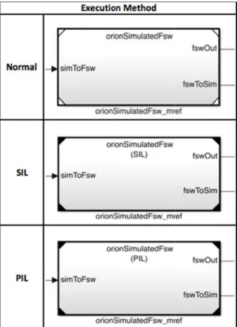
Figure 6. The
much on the sof w down develo level code. G slow developm d verification o d via the buil lopers to run a utocode, the bu cally in the nig
SIL) mode in ted, compiled, ed-loop with th ession suite is r il criteria are u n. Figure 6 would be see PDR, the softw d part of the FS eam is planning as well, levera hile SIL mode imulink model egrity target t t. e GN&C RAM SIL, and P ftware perform opment if exces Generating cod ment if tested e of the autocod ld and test ser all of the regres uild and test se ghtly runs. Us
Simulink, the wrapped in an he FLASHE s run with the sa used to determi 6 illustrates t en for the diff ware verificatio SW developme g to add Proces aging the auto uses the same ls, PIL mode u that matches MSES FSW mo PIL modes. mance early in t ssive emphasis de can also take excessively. T de, however, h rver. Instead ssion runs on t erver handles t sing the Softwa production C+ n s-function, a simulation. T ame logged da ine the success the only visu ferent simulati on will become ent process. T ssor In The Lo omated build a e compiler that uses an emulat the Orion flig
odel in Norma 10 the s is e a The has of the the are ++ and The ata, of ual ion e a The oop and t is ted ght al, An imp tracking testing FLASH develop develop to avoi standar A lot o project exampl fully te all flig proving (MCDC unachie comply from th rework end of t Collect provide become either p stack). develop provide is an ill to ident The au weekly and sto public Durabil standar large d four un GN&C When power, Orion s 750FX Side B each s allocati than 80 partitio mission change perform the m optimiz optimiz eases Further portant part o g. A major is the ability HE and RAMS pment. A pment is that b id issues and re rds compliance of time and eff by managin le, code with est. To comply ght code must g 100% Mod C). If the code evable and th y. Tracking an he pre-PDR st k and the need t the developme ting software e trends that es simpler to positive or neg As the m pment, there e useful trends lustration of an tify a large cod utomated build y metrics. The ored in a SQL domain, is AC lity)-compliant rd. This perm data sets with l nique metrics C FSW. targeting a re the software m spacecraft use clocked at 40 Bus). The GN econd to exe ion of less tha 0% of that fo on will have ns. Tracking t es made to the mance. Visibil most CPU p zation efforts zation in the ea CPU allocat rmore, because
11.
M
ETRIC f any large so r advantage i to continuousl SES models thr lesson learn better metrics t ework during e, and integrati ffort can be sav ng software m a high comple y with the Clabe fully cove dified Conditi e is too comple he code may n nd managing th
tage will grea to change prov ent cycle.
metrics early can help iden pin-point softw gative impact to metrics colle is a limited . Error! Refe n example of h de impact. d and test se ese metrics ar Lite [10] data CID (Atomicity t and implem mits optimum q little chance o are currently al-time operat must be optim es a relatively 00 Mhz with N&C partition ecute all capa an 500K. The for the EFT-1 more softwa the relative pe code that hav lity into which processing wi s. Being a arly stages of t tion issues l e keeping sim CS oftware projec n automated ly collect metr rough the entir
ned from th tracking may h
the unit testing ion phases of t ved at the bac metrics early
exity is very d ass-A software
ered and have ion Decision ex, 100% MCD need to be m he complexity o atly reduce thi ven algorithms in the project ntify problems ware changes o design param ection tools amount of da erence source
how trends cou
erver is used re continuously abase. SQLite y, Consistency ments most of querying for ex f data corrupti being collect ting system w mized appropria low powered a 100 Mhz FS is only allocat ability, and ha e CPU allocat flight, and t are capability erformance wil ve negative effe h algorithms ar ill aid in p able to cond the software de later in the mulation speed t is metric regression rics on the re period of he EFT-1 have helped g, software the project. ck end of a on. For difficult to e standards, e unit tests Coverage DC may be modified to of the code is potential toward the t will help early. It that make meters (like are under ata that to not found. uld be used to collect y collected e is in the y, Isolation, f the SQL xtraction of ion. Fifty-ted for the
with limited ately. The Power PC SB (Front-ted 7.5 ms as a stack tion is less the GN&C in future ll spotlight fects on the re utilizing prioritizing duct code evelopment program.. as high as
p r u s tr d o T C C U S P P R S r B R M C possible is ver record the buil useful in dete simulation buil rue in the co development. T of metrics colle Table 4. Exam Metric Code Cycloma Complexity Unit Test repo
SLOC Profile Report Per Regression Run Stack usage pe regression run Build time Run speed Model Advisor Compliance ry important f ld and run tim ermining chan ld and executi ontext of the Table 4 shows ected on the GN mple metrics c atic Code co early on orts Useful f progress SLOC i metric f ts n Useful are utiliz er n Stack i manage allocatio Major c recogniz CRs Simulat possible r The pas modelin for developme mes for each re nges that hav ion times. Th lessons learn examples of s N&C flight sof
collected for th Descript omplexity sho n to ease unit te for monitoring s of the entire p is a useful proj for resource pla for showing t zing the CPU t is limited an d to stay w on
changes in bu zed and isolat ion speeds sho e to ease develo
ss/fail data for ng standards co Figure 7. E ent, metrics th egression test a e slowed dow his is particular ned from EFT some of the typ ftware.
he GN&C FSW
tion
ould be manag esting effort g the unit testi
project ject manageme anning the methods th the most nd needs to ithin a speci uild time will ted to individu ould be as high opment r each model ompliance xample illustr hat are wn rly T-1 pes W. ged ing ent hat be ific be ual as on The Or based d flight c extende learned process softwar is a su softwar in this p Challen FSW interfac Solutio model-Challen dispers Solutio Challen Solutio develop integrat Challen capabil Solutio underly “ancest compar ration of softw rion GN&C te development o code for the f ed that experie d to improve
ses for a larg re required for ummary of c re developmen paper. nge: Provide can be deve ces between C
on: A new sim based design p
nge: Enhance sed teams opera
on: Utilize git d
nge: Speed up
on: Create a pment on s tion and elimin
nge: Implem lity for Simulin
on: Design and ying git capab tor” instances re these model
ware metrics tr
12.
S
UMMA eam has used of flight softw first Orion tes ence to build u the develop ger set of G r missions beyo challenges enc nt and resultin an environm eloped quickly and Simulink. mulation is built principles. collaboration ating on differe distributed ver model develop a process th eparate branc nate reserved c ment a usab nk models. d implement cu bility to extrac , and allow t s. rends. ARY its experience ware to produc st flight. The upon a number pment environ GN&C functioond LEO. The countered duri ng solutions as ment where m y and withou t natively in Si between geog ent secure netw rsion control. pment. at allows fo ches, with checkouts. ble graphical ustom scripts th ct “mine,” “th the developer in model-e model-effmodel-ectivmodel-e e team has r of lessons nment and nality and e following ing EFT-1 s discussed model-based ut TCP/IP imulink via graphically-works. or parallel continuous merging hat tap into heirs,” and
12
Challenge: Standardize the simulation model design, testing, validation, verification, and documentation.
Solution: Experiences from previous projects have been applied in the areas of model development. A standard API to unit test drivers has been created that facilitates creating, running, and documenting unit tests and associated models.
Challenge: Ease the burden of integrating multiple branches at once, leading to long integration cycles.
Solution: Responsibility of merging and correcting code is placed on each individual developer, which allows code changes to be integrated into the baseline and available for distribution within a matter of hours.
Challenge: Speed up and automate testing and integration for individual developers.
Solution: Utilize automated scripts and tools to merge and test code. Automatically integrate if all of the regression data are unchanged.
Challenge: Maintain and manage a working, compiled, and testable version of the autocode concurrently with model development.
Solution: Utilize automated nightly scripts on build and test server to autocode and test.
A model-based simulation environment in Simulink improves the process for development of on-orbit flight algorithms. Furthermore, a series of process improvements contribute greatly to the work flow of the team, including enhanced configuration management techniques for model-based software systems, automated code and artifact generation, and automated testing and integration.
A
CKNOWLEDGMENTSTo acknowledge all the contributors to the Orion GN&C model and process development is not possible since it was a product of a large, diverse team. However, the authors wish to acknowledge Chris Rossi from Draper Laboratory and Leon Gefert from the Glenn Research Center.
R
EFERENCES[1] Tamblyn, Scott, Henry, Joel, and King, Ellis, A Model-Based Design and Testing Approach for Orion GN&C
Flight Software Development. IEEE Aerospace
Conference. Big Sky, Montana, 2010.
[2] Henry, Joel R. and Jackson, Mark C., Orion GN&C Model Based Development Experience and Lessons Learned. AIAA GN&C Conference, 2012.
[3] The Mathworks online: http://www.mathworks.com/ [4] git online: http://git-scm.com/
[5] NASA’s Navigation and Ancillary Information Facility online: http://naif.jpl.nasa.gov/naif/toolkit.html
[6] Odegard, Ryan G., et. Al., Configuring the Orion Guidance, Navigation, and Control Flight Software for
Automated Sequencing. IEEE Aerospace Conference.
Big Sky, Montana, 2011.
[7] Lin, Alexander S., Penn, John M., Trick Simulation
Environment 07, NASA Tech Briefs, June 2012; 17-18.
[8] Walker, Gavin, Friedman, Jonathan, and Aberg Rob., Configuration Management of the Model-Based Design
Process. Proceedings of SAE World Congress &
Exhibition, 2007.
[9] Ensoftcorp online: http://www.ensoftcorp.com/simdiff/all-simdiff-and-simmerge-editions/
r m sy M R T D U g o th 2 p M U P R o M P reliability an multidisciplinar systems and a Member of the Ryan earned hi Technology in Draper Labora University of A guidance and operations for he Sierra Nev 2006 he joine previously wor Martin. University of Professional En Rendezvous an of the GN&C Mike holds a B Purdue Univers
B
IOG Ryan O engineer Laborato NASA on control a as syste design, nalysis. H ry system desi architecture d e Technical S is S.M. from th Aeronautics atory Fellowsh rizona in Mech Zoran M Aerospa State U M.S. in A the Univ His wor has bee navigation for the Space Shu vada Dream ed the Drape rked at Muniz Joel He Function NASA’s Houston backgro engineer Joel h Texas at A ngineer in the s Michael Enginee Aeronau Adminis the NAS developi Control, d Proximity op Engineering t B.S. degree in A sity. GRAPHY Odegard is a at the Charles ory. He has n guidance, na architecture de ems engineer database His backgrou ign optimizatio development. Staff at Drape he Massachuse and Astronau hip, and has a hanical Engine Milenkovic rec ace Engineerin University in Aerospace Eng versity of Hou rk at the Drap en focused on r rendezvous uttle, the Orio Chaser among er Laboratory Engineering enry is the GN nal Manager Johnson Spa n, Texas. ound inring and comp has a BSME Austin and is state of Texas. l Buttacoli is er with th utics and stration. He h SA community ing software , Trajectory D perations. He team for the O Aerospace Eng an aerospace s Stark Draper worked with avigation, and esign, as well ring concept design, and und includes on for complex Currently a er Laboratory, etts Institute of utics under a B.S. from the eering.