warwick.ac.uk/lib-publications
Original citation:
Al-Amin, Mohammad and Murphy, John D. (2016) Hydrogenation effect on low temperature
internal gettering in multicrystalline silicon. In: 43rd IEEE Photovoltaic Specialists
Conference, Portland, Oregon, USA, 5-10 Jun 2016. Published in: Proceedings of the 2016
IEEE 43rd Photovoltaic Specialists Conference (PVSC) 0585-0590.
Permanent WRAP URL:
http://wrap.warwick.ac.uk/85840
Copyright and reuse:
The Warwick Research Archive Portal (WRAP) makes this work by researchers of the
University of Warwick available open access under the following conditions. Copyright ©
and all moral rights to the version of the paper presented here belong to the individual
author(s) and/or other copyright owners. To the extent reasonable and practicable the
material made available in WRAP has been checked for eligibility before being made
available.
Copies of full items can be used for personal research or study, educational, or not-for profit
purposes without prior permission or charge. Provided that the authors, title and full
bibliographic details are credited, a hyperlink and/or URL is given for the original metadata
page and the content is not changed in any way.
Publisher’s statement:
“© 2016 IEEE. Personal use of this material is permitted. Permission from IEEE must be
obtained for all other uses, in any current or future media, including reprinting
/republishing this material for advertising or promotional purposes, creating new collective
works, for resale or redistribution to servers or lists, or reuse of any copyrighted component
of this work in other works.”
A note on versions:
The version presented here may differ from the published version or, version of record, if
you wish to cite this item you are advised to consult the publisher’s version. Please see the
‘permanent WRAP URL’ above for details on accessing the published version and note that
access may require a subscription.
Abstract—Giant magnetoresistance (GMR) magnetic field
sensors are compact, low power, high sensitivity devices that are low cost and have very simple supporting electronics. One of the disadvantages of GMR sensors can be their nonlinearity, hysteresis and temperature dependent output, which can reduce measurement accuracy. This paper presents an approach to improve the measurement accuracy of GMR sensors using a closed-loop circuit, which includes the sensor, a biasing coil and a feedback circuit. The current in the biasing coil is actively changed to ensure that the component of magnetic field along the sensitive axis of the device is held constant, so that as the external magnetic field or orientation of the GMR sensor changes, the output of GMR sensor remains stable. In this way, the external magnetic field component along the sensitive axis of the device can be calculated by measuring the current in the biasing coil surrounding the GMR sensor, regardless of the hysteresis and nonlinearly of GMR sensor. The linearity and accuracy of magnetic field measurements using a GMR sensor are significantly improved and a hardware prototype has been constructed and tested under a reference magnetic field.
Index Terms—Magnetic field measurement, GMR sensor, hysteresis, linearity, closed-loop.
I. INTRODUCTION
AGNETIC field sensing plays an important role in many
industrial applications, such as measurement of speed, position, current and earth’s magnetic field, non-destructive testing and condition monitoring [1]. Technological developments of magnetic field sensors have been driven by the need for improved sensitivity and reliability, smaller sensor size, and compatibility with electronic systems. Various techniques are used to measure both DC and AC magnetic field strength, each having unique properties that make it suitable for particular applications [2]-[4]. Due to their high sensitivity, small size, low power consumption and low cost, the giant magnetoresistance (GMR) sensors have been used in multifarious applications [5], [6]. However, they have some drawbacks such as nonlinearity, hysteresis and a temperature dependent output, that can reduce measurement accuracy [6]-[8]. The hysteresis and nonlinearity become more serious when measuring bipolar magnetic field. Moreover, the output
Manuscript received May 5, 2016. This work was supported by the UK Engineering and Physical Sciences Research Council through the UK Research Centre in Non-Destructive Evaluation (RCNDE) under Grant EP/L022125/1.
Z. Li and S. Dixon are with the Department of Physics, University of Warwick, Coventry CV4 7AL, UK (e-mail: [email protected]; [email protected]).
characteristic of GMR sensor is omnipolar, meaning that in normal use, the sensor only measures the magnitude of the magnetic field component along the direction of its sensitive axis.
When GMR sensors are used as a magnetometer, measurement accuracy becomes an important issue. It is desirable to make the output characteristic of GMR sensor linear and bipolar, and at certain field strengths in their operation range, for a field changing steadily in one direction, the GMR sensor can provide a reasonably linear output. In most applications however, this is not a practical arrangement. Some researchers have tried to model the hysteretic characteristics of GMR sensors to compensate the measurement error due to hysteresis [9], [10], and the modeling algorithms can improve the accuracy and linearize the output characteristic of GMR. However, these models are quite complex and the hysteretic models are not suitable for asymmetric magnetic field measurements. Using a bias field parallel to the sensitive axis can shift the operating point of GMR sensor to the linear portion of the characteristic curve, which will effectively result in a bipolar output signal and will also reduce the level of hysteresis [6], [11]-[15], but will not eliminate it completely. This biasing can be done either with an external permanent magnet [11] or a coil winding carrying a current [12]-[15], where the biasing magnetic field generated by a coil can be easily controlled. The biasing currents can be DC, AC, square wave and short pulses [12]-[15]. The control of the biasing current is usually open loop, so it needs relatively expensive set-ups to obtain accurate measurements of the current in the coil, but some studies have used closed-loop feedback of GMR sensor as current sensor [16].
This paper presents a new GMR circuit design that provides a significant improvement in the accuracy of the magnetic field measurement, using a closed-loop configuration, which consists of a GMR sensor, a biasing coil and a feedback circuit. The current flowing in the biasing coil is controlled by the GMR output signal, in such a way as to make the GMR output constant. Therefore, the magnetic field along the sensitive axis of the device can be calculated from the measurement of the biasing coil current, regardless of the hysteresis and nonlinearly of GMR sensors. The linearity and precision of magnetic field measurements are greatly improved using this method. The output characteristics of GMR sensor is introduced in Section II of the paper, whilst Section III describes the proposed closed-loop GMR sensor circuit in detail. The experimental results are shown in section IV.
A Closed-Loop Operation to Improve GMR
Sensor Accuracy
Zhichao Li, and Steve Dixon
Fig. 1. The output characteristics of AA002 at (a) 1 mA current supply and (b) 5 V voltage supply from [6].
TABLEI
KEY CHARACTERISTICS OF GMR SENSOR AA002FROM [6]. Linear range
(mT)
Sensitivity (mV/V/mT)
Nonlinearity Hysteresis Saturation field (mT)
Min Max Min Max
0.15 1.05 30 42 2% 4% 1.5
II. OUTPUT CHARACTERISTICS OF GMR SENSOR
The GMR sensors used in this paper are commercial devices AA002, manufactured by NVE [6]. The output curves of the AA002 sensor are shown in Fig. 1 and its key characteristics are shown in Table I.
It can be clearly seen in Fig. 1 that when this particular GMR sensor is powered by 1 mA current supply, the temperature has little influence on the linear characteristic curves. So in this
hysteresis in Table I are typical values only for unipolar operation: meaning that the sensor is subjected to magnetic field of one polarity relative to the sensitive axis of the device (e.g. 01 mT, or -0.2 mT -1.2 mT, but not -0.2 mT 1 mT). Bipolar operation, where the magnetic field passes from a negative value through zero to a positive value (or vice versa) will increase nonlinearity and hysteresis.
III. DESIGN AND ANALYSIS OF CLOSED-LOOP GMR SENSOR
CIRCUIT
To improve the measurement accuracy, a closed-loop GMR sensor circuit is designed. The schematic circuit diagram of the closed-loop GMR sensor circuit is shown in Fig. 2, which consists of a current source, a GMR sensor, a biasing coil, a differential amplifier, a subtractor and a push-pull amplifier. The differential amplifier, the subtractor and the push-pull amplifier compose the feedback circuit.
The GMR magnetometer is configured as a Wheatstone bridge by four 5 kΩ GMR resistors. Two of the resistors are sensing resistors (grey parts in Fig. 2) and the other two are reference resistors (white parts in Fig. 2), which are covered by a nickel-iron magnetic shield. In response to an external magnetic field, the exposed sensing resistors decrease in electrical resistance while the reference resistors remain unchanged, causing a voltage at the bridge output.
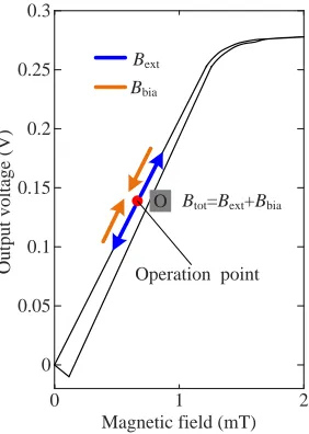
The current source supplies the 1 mA constant current to the GMR sensor. The GMR sensor measures the total magnetic field Btot, which is the sum of the external magnetic field Bext
and the biasing magnetic field Bbia generated by the coil. An
operation point in the middle part of the linear output curve is chosen and the corresponding output voltage is set as the reference voltage Vref. The output voltage Vop of the differential
amplifier is subtracted from the reference voltage. The push-pull amplifier drives the current in the biasing coil IC,
which can be calculated from the voltage Vm and resistance Rm
of the sampling resistor.
The current flowing in the biasing coil is controlled by the GMR output voltage to make the GMR output constant, as shown in Fig. 3. In what follows, when we discuss changes in the magnetic field, we will mean the component of magnetic field aligned along the sensitive axis of the GMR sensor. When the power to the GMR circuit is initially switched on, the electronics supplies a positive current pulse to the biasing coil, which is large enough to saturate the GMR sensor. This current is then gradually decreased over a several milliseconds, so that the output of the GMR sensor is maintained at a fixed level, in the middle of its dynamic range, in the linear region of operation. When the external magnetic field Bext increases, Vop
is larger than Vref, and the driving current IC in the coil decreases,
resulting in a decrease of biasing magnetic field Bbia. Therefore,
the total magnetic field Btot remains constant, regardless of
changes in Bext. Similarly, when the external magnetic field Bext
decreases, Vop is smaller than Vref, IC and the biasing magnetic
field Bbia increases, ensuring the total magnetic field Btot
Fig. 2. Schematic diagram of the closed-loop GMR sensor circuit, which consists of a current source, a GMR sensor, a biasing coil, a differential amplifier, a subtractor and a push-pull amplifier.
Fig. 3. Principle of the proposed biasing method.
calculated from measurement of the current through the bias coil, regardless of the hysteresis and nonlinearly of the GMR sensor.
Based on Fig. 2, the block diagram of the overall system is represented in Fig. 4. The GMR sensor produces a voltage Vs
proportional to the total magnetic field Btot along the sensitivity
axis. The output voltage Vs from GMR sensor can be described
as VsK Bs totK Bs( extBbia), where Ks is the sensitivity of
GMR sensor in the open-loop circuit.
The biasing coil current IC has can be expressed as [16]
ref ext C
C
( ) ( )
( )
( ) ( )
V G s B s I s
Z s G s K
(1)
where G s( )K Gs op( )s , Z s( )RmRCsLCRtot(1
Cs),tot m C
R R R ,
CLC Rtot, Gop(s) is the transfer function ofthe differential amplifier, RC and LC are the equivalent
[image:4.612.314.560.254.318.2]resistance and inductance of the biasing coil, respectively. The differential amplifier can be considered as a first-order
Fig. 4. Block diagram of the closed-loop GMR sensor circuit.
system to represent its open-loop behavior
op op
op ( )
1
K
G s
s
(2)
where Kop is the static gain, and
op is the time constant in thecase of open-loop.
The closed-loop system can be expressed by a whole second-order equation
op ref s op ext C
tot op C s op C
(1 ) ( )
( )
(1 )(1 )
s V K K B s
I s
R s s K K K
(3)
Usually,
op is the order of tens of milliseconds and
C is inthe order of microseconds. So in DC or low frequency applications
ops 1
and
Cs 1 (4)Based on (4), (3) can be simplified to
ref s op ext C
tot s op C ( )
( ) V K K B s
I s
R K K K
(5)
Because Rtot K K Ks op C [16], (5) can be further simplified to
ref ext C
s op C C
( )
( ) V B s
I s
K K K K
(6)
Vbridge
Vref V+
V- 1 mA
Current source
Subtractor Amplifier
Push-pull
Rm Vop
Vm
IC
Bext
Vs V Vpp
Sensing resistors Reference resistors
Magnetic field (mT) 0.1
0 0.05 0.15 0.2 0.25 0.3
0 1 2
O
u
tp
u
t
v
o
lt
ag
e
(V
)
Operation point Btot=Bext+Bbia
O Bext Bbia
s
K Gop( )s
V
s
V
ext
B
bia
B
ref
V
GMR sensor
Differential amplifier
1
m C C 1
R R sL
C
I
op
V Vpp
Push-pull
Sampling resistor and biasing coil
C
K
[image:4.612.104.245.260.458.2]component along the sensitive axis of the device, Btot, is stable.
So Ks in (6) represents the GMR sensor sensitivity at the
operation point Ks(O), which is constant. Equation (6) can be
rewritten as
ref ext C
s op C C
( ) ( )
(O)
V H s
I s
K K K K
(7)
Based on (7), it can be seen that the change of biasing current is proportional to the change of external magnetic field with the parameter KC, which only depends on the geometrical
characteristics of the biasing coil. As a consequence, the accuracy of the magnetic field measurement is significantly improved. The error due to hysteresis phenomenon of the GMR sensor is greatly reduced, and the issues of measuring small magnetic fields and a change in polarity of the background magnetic field are avoided.
IV. EXPERIMENTAL SETUP AND RESULTS
A prototype of the closed-loop GMR sensor circuit has been realized on the basis of the descriptions in section III. A biasing coil of 35 turns of 28 gauge insulated copper wire is wound to form a solenoid with an approximate diameter and length of 8 mm and 6 mm respectively around the AA002 GMR sensor, which has a sensitivity of approximately 175 mV/mT. The gain of the differential amplifier is 10, and the reference voltage is 1.35 V. The resistance of the sampling resistor is 5 Ω.
Helmholtz coils separated by 0.15 m, each of 128 turns, and a radius of 0.15 m are used to generate a reference magnetic field in order to verify the proposed method. The relationship between supply current Is and magnetic field strength B at the
center of axis between two coils is [17]
0128 s 8
0.15 5 5
I
B
(8)where
04π 10 T (A m) 7 , which is the permeability constant.In the experiment, the Helmholtz coils generate both bipolar and unipolar magnetic fields, including four ranges: (a) –0.2 mT~0.2 mT, (b) -0.1 mT~0.3 mT, (c) 0~0.3 mT, and (d) -0.3 mT~-0.05 mT. In order to test the biasing field circuit, the GMR sensor AA002 with and without biasing coil are placed in the central working area of the Helmholtz coils, and the GMR sensor sensitive axis is aligned in the same direction as the Helmholtz coils’ axes. All the system is placed horizontally and in an east-west direction, to minimise the corresponding DC field offset due to the earth’s magnetic field.
[image:5.612.317.563.49.335.2]Fig. 5 and Fig. 6 show the output voltage of GMR sensor without the biasing coil, and the bias coil current surrounding a GMR sensor, under both bipolar and unipolar magnetic fields, respectively. It can be seen that when measuring either bipolar or unipolar magnetic field, the hysteresis and nonlinearity of
Fig. 5. Output voltage of GMR sensor (AA002 only) and biasing current in the coil (AA002 with biasing coil) under bipolar magnetic field. (a) –0.2 mT~0.2 mT and (b) -0.1 mT~0.3 mT.
Fig. 6. Output voltage of GMR sensor (AA002 only) and biasing current in the coil (AA002 with biasing coil) under unipolar magnetic field. (a) 0~0.3 mT and (b) -0.3 mT~-0.05 mT.
GMR sensor output are obvious, which results low measuring precision of magnetic field. By using the proposed closed-loop
Magnetic field (mT)
-0.2 -0.1 0 0.1 0.2
0.09 0.1 0.11 0.12 0.13 0.14 0.15 -0.04 -0.02 0 0.02 0.04 0.06 0.08 B ia si n g c u rr en t (A ) O u tp u t v o lt ag e o f G M R s en so r
GMR sensor only
(a)
Magnetic field (mT)
-0.1 -0.05 0 0.05 0.1 0.15 0.2 0.25 0.3
0.07 0.08 0.09 0.1 0.11 0.12 0.13 0.14 0.15 -0.05 0 0.05 0.1 O u tp u t v o lt ag e o f G M R s en so r (V ) 0.15
GMR sensor with biasing coil GMR sensor only
B ia si n g c u rr en t (A ) (b) B ia si n g c u rr en t (A )
Magnetic field (mT)
0 0.05 0.1 0.15 0.2 0.25 0.3
0.07 0.08 0.09 0.1 0.11 0.12 0.13 0.14 0.15 0.1 0.05 0 O u tp u t v o lt ag e o f G M R s en so r (V )
GMR sensor with biasing coil GMR sensor only
(a)
Magnetic field (mT)
-0.3 -0.25 -0.2 -0.15 -0.1 -0.05
0.13 0.14 0.15 0.16 0.17 0.18 B ia si n g c u rr en t (A ) 0.15 0.1 0.05 O u tp u t v o lt ag e o f G M R s en so r (V )
GMR sensor with biasing coil GMR sensor only
[image:5.612.318.563.379.666.2]circuit, the hysteresis of the GMR sensor has been significantly reduced when measuring symmetric or asymmetric bipolar magnetic fields. The change of the current in the biasing coil is proportional to the change of the external magnetic field, ensuring high accuracy and linearity of magnetic field measurement. Moreover, the direction of the external magnetic field can also be obtained from the biasing current IC compared
with the IC(0), which is the current in the biasing coil without
external magnetic field.
V. CONCLUSIONS
The measurement accuracy of GMR sensor has been improved significantly with the use of the closed-loop circuit proposed in this paper. The operation principle and the block diagram of the whole system have been analysed. By using the biasing coil and the feedback circuit, the output voltage of GMR sensor is maintained at a constant value. The magnetic field can be calculated from measurement of the current in the biasing coil. The hysteresis and nonlinearity of the GMR sensor have been greatly eliminated. Therefore, the linearity and precision of magnetic field measurement has been significantly increased.
A hardware prototype is realized and tested under a reference magnetic field generated by Helmholtz coils. The current in the biasing coil is linear for both bipolar (either symmetric or asymmetric) and unipolar magnetic fields. Moreover, the direction of the external magnetic field can be determined, which is not the case when using an isolated GMR sensor.
The closed-loop GMR sensor circuit presented here has a wide range of applications, and this technique can also be extended to other magnetic field sensors with nonlinear and hysteretic output issues.
REFERENCES
[1] M. J. Caruso, T. Bratland, C. H. Smith, and R. Schneider, “A new
perspective on magnetic field sensing,” SensorsMag., vol. 15, no. 12, pp.
34-46, Dec. 1998.
[2] J. E. Lenz, “A review of magnetic sensors,” Proceeding of the IEEE, vol.
78, no. 6, pp. 973–989, Jun. 1990.
[3] J. Lenz, and A. S. Edelstein, “Magnetic sensors and their applications,”
IEEE Sensors J., vol. 6, no. 3, pp. 631-649, Jun. 2006.
[4] P. Ripka, and M. Janosek, “Advances in magnetic field sensors,” IEEE
Sensors J., vol. 10, no. 6, pp. 1108-1116, Jun. 2010.
[5] J. M. Daughton, “GMR applications,” J. Magn. Magn. Mater., vol. 192,
no. 2, pp. 334-342, Feb. 1999.
[6] NVE magnetic sensor catalog. NVE Corporation, Eden Prairie, MN, USA,
February 6, 2012.
[7] J. Daughton, and Y. Chen, “GMR materials for low field applications,”
IEEE Trans. Magn., vol. 29, no. 3, pp. 2705–2710, Nov. 1993.
[8] J. Daughton, J. Brown, E. Chen, A. Pohm, and A. Kude, “Magnetic field
sensors using GMR multilayers,” IEEE Trans. Magn., vol. 30, no. 6, pp.
4608–4610, Nov. 1994.
[9] J. Han, J. Hu, Y. Ouyang, S. X. Wang, and J. He, “Hysteretic modeling of
output characteristics of giant magnetoresistive current sensors,” IEEE
Trans. Ind. Electron., vol. 62, no. 1, pp. 516-524, Jan. 2015.
[10] I. Jedlicska, R. Weiss, and R. Weigel, “Linearizing the output
characteristic of GMR current sensors through hysteresis modeling,”
IEEE Trans. Ind. Electron., vo. 57, no. 5, pp. 1728-1734, May. 2010.
[11] A. J. Lopez-Martin, and A. Carlosena, “Novel automatic digital
calibration techniques for GMR sensors,” in Proc. IEEE Sensors 2014,
Valencia, 2014, pp. 2078-2081.
[12] M. Vopálenský, P. Ripka, J. Kubı́k, and M. Tondra, “Improved GMR
sensor biasing design,” Sens Actuators A Phys, vol. 110, no. 1, pp.
254-258, Feb. 2004.
[13] P. Ripka, M. Tondra, J. Stokes, and R. Beech, “AC-driven AMR and
GMR magnetoresistors,” Sens Actuators A Phys, vol. 76, no. 1, pp.
225-230, Aug. 1999.
[14] A. Bernieri, G. Betta, L. Ferrigno, and M. Laracca, “Improving
performance of GMR sensors,” IEEE Sensors J., vol. 13, no. 11, pp.
4513-4521, Nov. 2013.
[15] F. Xie, R. Weiss, and R. Weigel, “Hysteresis compensation based on
controlled current pulses for magnetoresistive sensors,” IEEE Trans. Ind.
Electron., vol. 62, no. 12, pp. 7804-7809, Dec. 2015.
[16] X. Yang, H. Liu, Y. Wang, Y. Wang, G. Dong, and Z. Zhao, “A giant
magneto resistive (GMR) effect based current sensor with a toroidal
magnetic core as flux concentrator and closed-loop configuration,” IEEE
Trans. Appl. Supercond., vol. 24, no. 3, pp. 1-5, Jun. 2014.
[17] Helmholtz coil manual. EMC test systems, 2001.
Zhichao Li was born in Hebei, China. He
earned his B.S., M.S., and Ph. D. degrees in from Harbin Institute of Technology, China, in 2008, 2010, and 2014, respectively. He is currently a Research Fellow in Ultrasonics Group at University
of Warwick, studying magnetic
monitoring of corrosion in pipelines by using metal magnetic memory (MMM) method and magnetic tomography measurement (MTM).
Steve Dixon is the director of the Centre
![Fig. 1. The output characteristics of AA002 at (a) 1 mA current supply and (b) 5 V voltage supply from [6]](https://thumb-us.123doks.com/thumbv2/123dok_us/9474776.453811/3.612.78.266.51.501/fig-output-characteristics-aa-current-supply-voltage-supply.webp)