http://wrap.warwick.ac.uk
Original citation:
Luo, Xing, Wang, Jihong, Dooner, Mark and Clarke, Jonathan. (2015) Overview of
current development in electrical energy storage technologies and the application
potential in power system operation. Applied Energy, Volume 137 . pp. 511-536. ISSN
0306-2619
Permanent WRAP url:
http://wrap.warwick.ac.uk/63615
Copyright and reuse:
The Warwick Research Archive Portal (WRAP) makes this work of researchers of the
University of Warwick available open access under the following conditions.
This article is made available under the Creative Commons Attribution 3.0 (CC BY 3.0)
license and may be reused according to the conditions of the license. For more details
see:
http://creativecommons.org/licenses/by/3.0/
A note on versions:
The version presented in WRAP is the published version, or, version of record, and may
be cited as it appears here.
Overview of current development in electrical energy storage
technologies and the application potential in power system operation
q
Xing Luo
⇑, Jihong Wang, Mark Dooner, Jonathan Clarke
School of Engineering, The University of Warwick, Coventry CV4 7AL, UK
h i g h l i g h t s
An overview of the state-of-the-art in Electrical Energy Storage (EES) is provided. A comprehensive analysis of various EES technologies is carried out.
An application potential analysis of the reviewed EES technologies is presented.
The presented synthesis to EES technologies can be used to support future R&D and deployment.
a r t i c l e
i n f o
Article history:
Received 14 March 2014
Received in revised form 3 September 2014 Accepted 25 September 2014
Available online 16 October 2014
Keywords:
Electrical energy storage Overview
Power system
Technical and economic performance features
Application potential
a b s t r a c t
Electrical power generation is changing dramatically across the world because of the need to reduce greenhouse gas emissions and to introduce mixed energy sources. The power network faces great chal-lenges in transmission and distribution to meet demand with unpredictable daily and seasonal varia-tions. Electrical Energy Storage (EES) is recognized as underpinning technologies to have great potential in meeting these challenges, whereby energy is stored in a certain state, according to the tech-nology used, and is converted to electrical energy when needed. However, the wide variety of options and complex characteristic matrices make it difficult to appraise a specific EES technology for a particular application. This paper intends to mitigate this problem by providing a comprehensive and clear picture of the state-of-the-art technologies available, and where they would be suited for integration into a power generation and distribution system. The paper starts with an overview of the operation principles, technical and economic performance features and the current research and development of important EES technologies, sorted into six main categories based on the types of energy stored. Following this, a comprehensive comparison and an application potential analysis of the reviewed technologies are presented.
Ó2014 The Authors. Published by Elsevier Ltd. This is an open access article under the CC BY license (http://creativecommons.org/licenses/by/3.0/).
1. Introduction
Global electricity generation has grown rapidly over the last decade. As of 2012, the annual gross production of electricity reached approximately 22,200 TW h, of which fossil fuels (includ-ing coal/peat, natural gas and oil) contribute around 70% of global electricity generation[1–3]. To maintain the power network stabil-ity, the load balance has mainly been managed through fossil fuel power plants. To achieve the target of reducing CO2 emissions,
future electricity generation will progress with diminishing reliance on fossil fuels, growing use of renewable energy sources
and with a greater respect for the environment[3]. However, most renewable energy sources are intermittent in their nature, which presents a great challenge in energy generation and load balance maintenance to ensure power network stability and reliability. Great efforts have been made in searching for viable solutions, including Electrical Energy Storage (EES), load shifting through demand management, interconnection with external grids, etc. Amongst all the possible solutions, EES has been recognized as one of the most promising approaches[4,5].
EES technology refers to the process of converting energy from one form (mainly electrical energy) to a storable form and reserv-ing it in various mediums; then the stored energy can be converted back into electrical energy when needed[4,5]. EES can have multi-ple attractive value propositions (functions) to power network operation and load balancing, such as: (i) helping in meeting peak electrical load demands, (ii) providing time varying energy
http://dx.doi.org/10.1016/j.apenergy.2014.09.081
0306-2619/Ó2014 The Authors. Published by Elsevier Ltd.
This is an open access article under the CC BY license (http://creativecommons.org/licenses/by/3.0/).
q
This paper is included in the Special Issue of Energy Storage edited by Prof. Anthony Roskilly, Prof. Phil Taylor and Prof. Yan.
⇑ Corresponding author. Tel.: +44 247 6522333.
E-mail address:[email protected](X. Luo).
Contents lists available atScienceDirect
Applied Energy
management, (iii) alleviating the intermittence of renewable source power generation, (iv) improving power quality/reliability, (v) meeting remote and vehicle load needs, (vi) supporting the realization of smart grids, (vii) helping with the management of distributed/standby power generation, (viii) reducing electrical energy import during peak demand periods.
In many scenarios, demand for EES and selection of appropriate EES technologies have been considered to be important and chal-lenging in countries with a relatively small network size and iner-tia. For example, the UK electric power network currently has a capacity of Pumped Hydroelectric Storage (PHS) at 27.6 GW h[6]. Although PHS facilities have been built worldwide as a mature and commercially available technology, it is considered that the potential for further major PHS schemes is restricted in the UK
[6]. Therefore, it is of great importance that suitable EES technolo-gies in addition to PHS are explored. Derived from the study of recent publications,Fig. 1illustrates various EES technologies with potentials to address the challenges faced by the UK energy sys-tems[4,6,7–9]. Many countries potentially need to address similar challenges which can be solved or improved by suitable EES technologies.
Due to the great potential and the multiple functions of EES, in the literature many authors have reviewed and summarized the EES research and development, demonstrations and industrial applications from different perspectives, particularly in recent years. The paper presented by Ibrahim et al. highlighted the need to store energy for improving power networks and maintaining load levels[10]. A group of characteristics of different EES technol-ogies is given, which can help improve performance and cost esti-mates for storage systems. However relatively few references are cited in[10]. Chen et al. provided a well-organized and compre-hensive critical review on progress in EES systems, which covered various types of EES technologies and their applications/deploy-ment status [4]. The discussion on the selection of appropriate EES candidates for specific applications was relatively brief. Hall et al. also presented a review article concentrating on several EES technologies, i.e., batteries, supercapacitors, superconducting mag-netic energy storage and flywheels [11]. Liu et al. provided an insightful review of the advanced materials for several EES tech-nologies [12]. The strategies for developing high-performance
hydrogen storage materials and electrochemical lithium-ion bat-tery materials were discussed in detail[12]. The paper also high-lighted the prospects in the future development of advanced materials for EES. With the rapid penetration of intermittent renewables, the review articles[13–16]have made effort to assess and summarize the EES options for increased renewable electricity applications. Díaz-González et al.[13]and Zhao et al.[15]focus on the review of EES technologies for wind power applications. A detailed discussion of existing EES applications in wind power is a highlight provided by the article[13], whilst the planning issues, the operation and control strategies of the ESS applications for wind power integration support are summarized by the paper
[15]. Furthermore, from a novel viewpoint, Connolly et al. assessed available computer tools for analyzing the integration of renew-able energy into various energy systems[17]. Researchers have also reviewed specific aspects of EES systems, such as in[18–22]. For instance, Dunn et al. contributed a high quality review on bat-tery energy storage for the grid applications, mainly focusing on commercially available sodium–sulfur batteries, relatively low cost redox-flow batteries and developing lithium-ion batteries, all with the aim to be used in grid storage[22]. The reviews of the develop-ments and challenges in materials for electrochemical relevant energy storage are presented in[23–25]. For example, Whitting-ham addressed the current challenges in the subject of electro-chemical energy storage materials, which can be summarized as: reducing the cost and extending the lifetime of devices whilst improving their performance and making them more environmen-tally friendly[23]. In addition, some journals have published spe-cial issues dedicated to EES research and development, such as the special issue in 2013 from the Wiley journal Advanced Func-tional Materials: ‘‘Grand Challenges in Energy Storage’’.
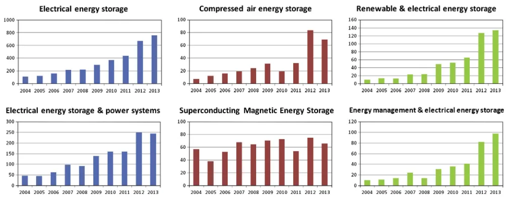
[image:3.595.106.476.498.736.2]A brief statistical study has been carried out to ascertain the trends in EES related research using the search engine ‘Web of Sci-ence’ and choosing ‘Topic’ as the search field. Fig. 2 shows the results detailing the number of research papers published in six EES related fields over the past ten years (2004–2013). The titles of the subfigures inFig. 2are the input keywords used in the search engine. The results indicate that research in EES in the past ten years has tended to increase, with rapid increases in 2012 and 2013. In particular, research into compressed air energy storage
grew significantly in 2012 whilst, in contrast, research into super-conducting magnetic energy storage has remained relatively sta-ble. It can also be seen that there has been a large increase in the research into renewable and energy management with EES topics. The statistic figure in EES research literatures shows that the entire EES research and technology development have changed and advanced rapidly in the years since some previous reviews, such as[4,10,11], were published. Thus it is timely to have a new critical overview of the current development in EES.
Although the potential benefits of EES installation to power sys-tem operation have been widely recognized, some significant chal-lenges in the deployment of EES systems exist, mainly in: (1) how to choose the suitable EES technology to match the power system application requirements; (2) how to accurately evaluate the actual values of deployed EES facilities including technical and eco-nomic benefits; (3) how to bring the cost down to a realistically acceptable level for deployment, especially for newly developing EES technologies.
The objective of this paper is to provide a updated picture of the state-of-the-art EES technologies, in comparison with the previous review articles[4,10,11]. The paper begins with an overview of the operation principles, technical and economic performance features and the current research and development of important EES technologies. Following this, a comprehensive comparison of EES technologies is conducted. The paper presents a detailed summari-zation and predication of the existing and promising EES technol-ogy options for different power system applications with their corresponding technical specifications. The overview will help address the challenges faced in deployment of EES and provide useful information and guidance in selecting suitable technologies for specific applications based on the nature of EES characteristics.
2. Classification of electrical energy storage technologies
There are several suggested methods for categorization of vari-ous EES technologies, such as, in terms of their functions, response times, and suitable storage durations[4,26,27]. One of the most widely used methods is based on the form of energy stored in the system[15,16]as shown inFig. 3, which can be categorized into mechanical (pumped hydroelectric storage, compressed air energy storage and flywheels), electrochemical (conventional rechargeable batteries and flow batteries), electrical (capacitors, supercapacitors and superconducting magnetic energy storage), thermochemical (solar fuels), chemical (hydrogen storage with fuel
cells) and thermal energy storage (sensible heat storage and latent heat storage). A detailed description and discussion of each type of EES technology will be given in the next section following the above order of category.
3. Description of electrical energy storage technology
3.1. Pumped Hydroelectric Storage (PHS)
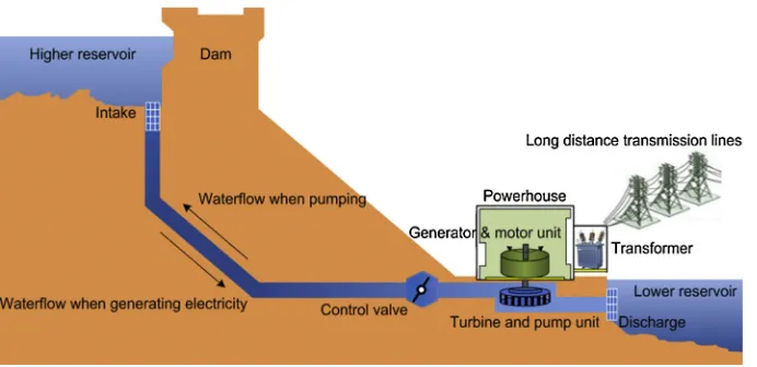
PHS is an EES technology with a long history, high technical maturity and large energy capacity. With an installed capacity of 127–129 GW in 2012, PHS represents more than 99% of worldwide bulk storage capacity and contributes to about 3% of global gener-ation[26,28,29]. As shown inFig. 4, a typical PHS plant uses two water reservoirs, separated vertically. During off-peak electricity demand hours, the water is pumped into the higher level reservoir; during peak hours, the water can be released back into the lower level reservoir. In the process, the water powers turbine units which drive the electrical machines to generate electricity. The amount of energy stored depends on the height difference between the two reservoirs and the total volume of water stored. The rated power of PHS plants depends on the water pressure and flow rate through the turbines and rated power of the pump/turbine and generator/motor units, and[30].
Various PHS plants exist with power ratings ranging from 1 MW to 3003 MW, with approximately 70–85% cycle efficiency and more than 40 years lifetime[4,29,31,32]. Some PHS facilities along with their features are listed inTable 1. The nature of the operation of PHS systems means that their applications mainly involve energy management in the fields of time shifting, frequency con-trol, non-spinning reserve and supply reserve. However, with the restriction of site selection, PHS plants suffer long construction time and high capital investment.
Recently, with the advance of technology, some PHS plants using flooded mine shafts, underground caves and oceans as reser-voirs have been planned or are in operation , such as the Okinawa Yanbaru in Japan, a 300 MW seawater-based PHS plant in Hawaii, the Summit project in Ohio and the Mount Hope project in New Jersey[28,34,35]. In addition, wind or solar power generation cou-pled with PHS is now being developed. This could help the adop-tion of renewable energy in isolated or distributed networks
[image:4.595.50.554.63.260.2]with higher speed and larger capacity compared to the current technical level, installing centralized monitoring and using intelli-gent control systems[26,28,38].
3.2. Compressed Air Energy Storage (CAES)
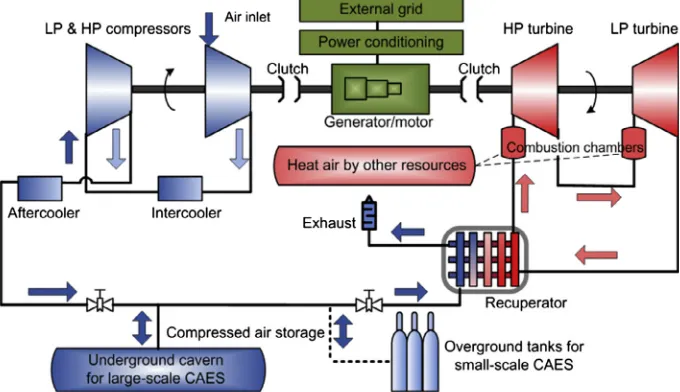
In addition to PHS, CAES is another type of commercialized EES technology which can provide power output of over 100 MW with a single unit. A schematic diagram of a CAES plant is shown in
Fig. 5. During the periods of low power demand, the surplus elec-tricity drives a reversible motor/generator unit in turn to run a chain of compressors for injecting air into a storage vessel, which is either an underground cavern or over ground tanks. The energy is stored in the form of high pressure air. When the power gener-ation cannot meet the load demand, the stored compressed air is released and heated by a heat source which can be from the com-bustion of fossil fuel or the heat recovered from the compression
process. The compressed air energy is finally captured by the tur-bines. The waste heat from the exhaust can be recycled by a recu-perator unit (Fig. 5).
[image:5.595.121.467.283.451.2]The world’s first utility-scale CAES plant, the Huntorf power plant, was installed in Germany in 1978[39–41]. It uses two salt domes as the storage caverns and it runs on a daily cycle with 8 h of compressed air charging and 2 h of operation at a rated power of 290 MW[39]. This plant provides black-start power to nuclear units, back-up to local power systems and extra electrical power to fill the gap between the electricity generation and demand. Another commercial CAES plant started operation in McIntosh, the US, in 1991[39–41]. The 110 MW McIntosh plant can operate for up to 26 h at full power. The compressed air is stored in a salt cavern. A recuperator is operated to reuse the exhaust heat energy. This reduces the fuel consumption by 22– 25% and improves the cycle efficiency from42% to54%, in com-parison with the Huntorf plant[4,42]. These two CAES plants have Fig. 3.Classification of EES technologies by the form of stored energy.
[image:5.595.30.557.507.568.2]Fig. 4.A pumped hydroelectric storage plant layout.
Table 1
Selected pumped hydroelectric storage plants[4,26,31–33].
Plant name Country Power rating Features
Rocky river PHS plant US 32 MW The world’s first large-scale commercial PHS plant
Bath County PHS plant US 3003 MW The world’s largest power rated PHS plant
Okinawa Yanbaru PHS Japan 30 MW Only commercial seawater PHS plant
Hawaiian Elec. Co. PHS facility US — Claimed 87% relatively high cycle efficiency
consistently shown good performances with 91.2–99.5% starting and running reliabilities[38,39].
CAES system can be built to have small to large scale of capac-ities; CAES technology can provide the moderate speed of responses and good partial-load performance. The practical uses of large-scale CAES plants involve grid applications for load shift-ing, peak shavshift-ing, and frequency and voltage control. CAES can work with intermittent renewable energy applications, especially in wind power, to smooth the power output, which have attracted much attentions from academic researchers and industrial sectors as described in [40,43–45]. The major barrier to implementing large-scale CAES plants is identifying appropriate geographical locations which will decide the main investment cost of the plant. Relative low round trip efficiency is another barrier for CAES com-pared to PHS and battery technologies.
In addition, the developing Liquid Air Energy Storage (LAES) has many components which are the same or similar as those used for CAES, such as compressors, turbines, electric machines and heat exchangers. Considering the type of energy stored, LAES can be classified into thermal energy storage, which will be introduced in Section3.10.
Currently, the newly developing Advanced Adiabatic CAES (AA-CAES) is attracting attention. AA-CAES technology is normally integrated with a thermal energy storage subsystem, which has no fuel combustion involved in the expansion mode[39,42,43,46]. The world’s first AA-CAES demonstration plant – ADELE – is in the development stage, at Saxony-Anhalt in Germany. The plant will have a storage capacity of 360 MWh and an electric output of 90 MW, aiming for70% cycle efficiency[43]. Because its com-pression mode will be powered by wind energy, the ADELE plant emits no CO2in a full cycle. The US based LightSail Energy Ltd. is
also developing the AA-CAES facilities by using reversible recipro-cating piston machines [46]. In 2007 Luminant and Shell-Wind Energy proposed wind farm projects involving CAES in Texas, intending to evaluate the potential of incorporating CAES facilities in conjunction with the wind farm; after a long wait, in 2013 the project got underway and hosting 317 MW of CAES has been set as the current target[39,44]. In addition, a comparison between different adiabatic CAES plant configurations was recently pub-lished in[47].
Recently, apart from using salt caverns, researchers have attempted to study other geological structures for use in under-ground CAES technology. A 2 MW field test program has used a
[image:6.595.131.471.70.266.2]concrete-lined tunnel in an abandoned mine in Japan[39,48]. A test facility made by Electric Power Research Institute and others utilized a hard rock cavern with water compensation[49]. Italy’s Enel operated a 25 MW porous rock based CAES facility in Sesta – the test was stopped due to a disturbed geothermal issue[39]. The Iowa Stored Energy Park project aimed to use porous sand-stone aquifers to build an underground reservoir for constructing a 270 MW CAES plant; unfortunately, this project stopped in 2011 as the field test result indicated that the geological structure in Iowa cannot obtain a fast enough flow for large-scale CAES[50]. Over ground small-scale CAES has recently undergone rapid development. It can be used as an alternative to the battery for industrial applications, such as Uninterruptible Power Supplies (UPS) and back-up power systems. Compressed air battery systems developed by the UK based Flowbattery (previously named Pnu Power) were recently successfully commercialized [51]. It uses pre-prepared compressed air from air cylinders to drive a combina-tion of a scroll expander and a generator to produce electricity
[51,52]. In addition, the guideline study for the efficient design and sizing of small-scale CAES pressure vessels considering mini-mizing its cost was reported in[53]. Also, the feasibility on the direct mechanical coupling of a wind turbine and a scroll expander with small-scale CAES has been studied by the University of War-wick, and its on-site tests are on-going[52,54].
3.3. Flywheel Energy Storage (FES)
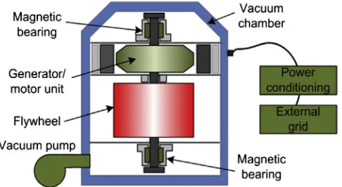
A modern FES system is composed of five primary components: a flywheel, a group of bearings, a reversible electrical motor/gener-ator, a power electronic unit and a vacuum chamber[18].Fig. 6
shows the simplified structure of a modern FES facility. FES sys-tems use electricity to accelerate or decelerate the flywheel, that is, the stored energy is transferred to or from the flywheel through an integrated motor/generator. For reducing wind shear and energy loss from air resistance, the FES system can be placed in a high vacuum environment. The amount of energy stored is depen-dent on the rotating speed of flywheel and its inertia.
FES can be classified into two groups: (1) low speed FES: it uses steel as the flywheel material and rotates below 6103rpm; (2)
high speed FES: it uses advanced composite materials for the fly-wheel, such as carbon-fiber, which can run up to105rpm[55].
non-contact magnetic bearings to mitigate the wear of bearings, thereby improving the efficiency. The application areas of high speed FES are continuously expanding, mainly in high power qual-ity and ride-through power service in traction and the aerospace industry [56]. The specific energy of low speed flywheels is
[image:7.595.39.282.67.200.2]5 W h/kg, and the high speed composite rotor can achieve a spe-cific energy of up to100 W h/kg[57]. The cost of high speed com-posite systems can be much higher than that of conventional metal flywheel systems. FES has some favorable characteristics, including high cycle efficiency (up to95% at rated power), relatively high power density, no depth-of-discharge effects and easy mainte-nance[18,55,57].
Table 2lists some selected FES facilities. In June 2011, a 20 MW modular plant built by Beacon Power was put into commercial operation in New York, which was the largest advanced EES facility operating in North America[58,59]. It employs 200 high speed fly-wheel systems to provide fast response frequency regulation ser-vices to the grid, providing 10% of the whole state frequency regulation demand[58,59]. Normally, FES devices can supply suffi-cient power in a short time period with modest capacity. Thus it is not used as standalone backup power unless operated with other EES or power generation systems, such as batteries or fuel-fired generators. The main weakness of FES is that flywheel devices suf-fer from the idling losses during the time when the flywheel is on standby. This can lead to relatively high self-discharge, up to20% of stored capacity per hour[57].
Currently, the research and development area of FES includes the material of the flywheel for increasing their rotation speed capabilities and power densities, high speed electrical machines, high carrying capacity of the bearings and the flywheel array tech-nology. An advance in FES technology is the High Temperature Superconductor (HTS) bearings which is a promising option for improving bearing performance. The US Argonne National Labora-tory developed a 2 kW h FES system using high-temperature superconductors and permanent magnets as passive bearings for a feasibility study[61]. A model-based power flow control strategy has been studied for improving flywheel performance in high power pulse systems [62]. The rail traction industry has tested FES devices for trackside voltage support [63]. Optimizing
flywheels for relatively long-term operation (up to several hours) are being studied for use in vehicles and power plants[26].
3.4. Battery Energy Storage (BES)
The rechargeable battery is one of the most widely used EES technologies in industry and daily life.Fig. 7shows the simplified operational principle of a typical BES system. A BES system consists of a number of electrochemical cells connected in series or parallel, which produce electricity with a desired voltage from an electro-chemical reaction. Each cell contains two electrodes (one anode and one cathode) with an electrolyte which can be at solid, liquid or ropy/viscous states[64,65]. A cell can bi-directionally convert energy between electrical and chemical energy. During discharg-ing, the electrochemical reactions occur at the anodes and the cathodes simultaneously. To the external circuit, electrons are pro-vided from the anodes and are collected at the cathodes. During charging, the reverse reactions happen and the battery is recharged by applying an external voltage to the two electrodes (Fig. 7).
Batteries can be widely used in different applications, such as power quality, energy management, ride-through power and transportation systems. The construction of BES systems takes a relatively short time period (roughly within 12 months) [4,66]. The location for installation can be quite flexible, either housed inside a building or close to the facilities where needed. Currently, relatively low cycling times and high maintenance costs have been considered as the main barriers to implementing large-scale facil-ities. The disposal or recycling of dumped batteries must be consid-ered if toxic chemical materials are used[9]. Furthermore, many types of battery cannot be completely discharged due to their life-time depending on the cycle Depth-of-Discharge (DoD) [13]. A description of several important BES technologies will be pre-sented in the following five subsections. The chemical reactions taking place in these battery types are listed inTable 3.
3.4.1. Lead–acid batteries
The most widely used rechargeable battery is the lead–acid battery[4,10]. The cathode is made of PbO2, the anode is made
ofPb, and the electrolyte is sulfuric acid. Lead–acid batteries have fast response times, small daily self-discharge rates (<0.3%), rela-tively high cycle efficiencies (63-90%) and low capital costs (50–600 $/kW h) [4,14,57,69]. Some examples of EES facilities using lead–acid batteries are listed inTable 4. Lead–acid batteries can be used in stationary devices as back-up power supplies for data and telecommunication systems, and energy management applications. Also, they have been developed as power sources for hybrid or full electric vehicles. However, there are still limited installations around the world as utility-scale EES, mainly due to their relatively low cycling times (up to2000), energy density (50–90 W h/L) and specific energy (25–50 Wh/kg) [4,70,71]. In addition, they may perform poorly at low temperatures so a ther-mal management system is norther-mally required, which increases the cost[72].
[image:7.595.29.552.683.753.2]Currently, the research and development of lead–acid batteries focuses on: (1) innovating materials for performance improvement, Fig. 6.System description of a flywheel energy storage facility.
Table 2
Selected flywheel energy storage facilities[18,55,57–60].
Firms/Institutes Characteristics Application area
Active Power Company Clean Source series 100–2000 kW Backup power supply, UPS systems
Beacon Power Company 100/150 kW a unit, 20 MW/5 MW h plant Freq. regulation, power quality, voltage support
Boeing Phantom Works 100 kW/5 kW h, HT magnetic bearings Power quality and peak shaving
Japan Atomic Energy Center 235 MVA, steel flywheel High power supply to Nuclear fusion furnace
Piller power systems Ltd. 3600–1500 rpm, 2.4 MW for 8 s Ride-through power and sources of backup power
NASA Glenn research center 2104
–6104
such as extending cycling times and enhancing the deep discharge capability; (2) implementing the battery technology for applica-tions in the wind, photovoltaic power integration and automotive sectors. Several advanced lead–acid batteries that have fast responses comparable to flywheels and supercapacitors are being developed or are in the demonstration phase, such as Ecoult Ultr-aBattery smart systems and Xtreme Power advanced lead–acid ‘‘Dry Cell’’[73,74].
3.4.2. Lithium-ion (Li-ion) batteries
In a Li-ion battery, the cathode is made of a lithium metal oxide, such as LiCoO2and LiMO2, and the anode is made of graphitic
car-bon. The electrolyte is normally a non-aqueous organic liquid con-taining dissolved lithium salts, such as LiClO4 [13]. The Li-ion
battery is considered as a good candidate for applications where the response time, small dimension and/or weight of equipment are important (milliseconds response time, 1500–10,000 W/L,
75–200 W h/kg, 150–2000 W/kg) [4,9,26,57]. Li-ion batteries also have high cycle efficiencies, up to 97% [4,26]. The main drawbacks are that the cycle DoD can affect the Li-ion battery’s lifetime and the battery pack usually requires an on-board com-puter to manage its operation, which increases its overall cost.
The current research focuses for the Li-ion battery include: (1) increasing battery power capability with the use of nanoscale materials; (2) enhancing battery specific energy by developing advanced electrode materials and electrolyte solutions. Several companies have experience in using Li-ion batteries in the util-ity-scale energy market. The U.S. based AES Energy Storage has been commercially operating a Li-ion BES system (8 MW/2 MW h in 2010, enlarged 16 MW in 2011) in New York for supplying fre-quency regulation [8,77]. The AES also installed a 32 MW/ 8 MW h Li-ion BES system (Laurel Mountain) for supporting a 98 MW wind generation plant in 2011[77,78]. Currently, the larg-est European Li-ion battery EES trial is underway in the UK. The project will deploy a 6 MW/10 MWh Li-ion battery at a primary substation to assess the cost effectiveness of EES as part of the UK’s Carbon Plan [79]. The companies claimed that the storage could save more than $9 million compared to traditional system upgrades; the project can be used to balance the intermittency of wind and other renewables[79]. Also, in December 2013 Toshiba announced a project to install a 40 MW/20 MWh Li-ion battery project in Tohoku, which will help integrate renewables into the grid[80]. In addition, Li-ion batteries are now applied in Hybrid and full Electric Vehicles (HEVs and EVs), which use large-format cells and packs with capacities of 15–20 kW h for HEVs and up to 50 kW h for EVs[28].
3.4.3. Sodium–sulfur (NaS) batteries
A NaS battery uses molten sodium and molten sulfur as the two electrodes, and employs beta alumina as the solid electrolyte. The reactions normally require a temperature of 574–624 K to ensure the electrodes are in liquid states, which leads to a high reactivity
[image:8.595.146.458.68.245.2] [image:8.595.43.293.317.457.2][8]. The desirable features of NaS batteries include relatively high energy densities (150–300 W h/L), almost zero daily self-discharge, higher rated capacity than other types of batteries (up to 244.8 MW h) and high pulse power capability[13,26,81]. The bat-tery uses inexpensive, non-toxic materials leading to high recycla-bility (99%) [4,13]. However, the limitations are high annual Fig. 7.Schematic diagram of a battery energy storage system operation.
Table 3
[image:8.595.42.288.498.585.2]Chemical reactions and single unit voltages of main batteries available to EES
[4,13,67,68].
Battery type Chemical reactions at anodes and cathodes Unit voltage
Lead–acid PbþSO2
4 ()PbSO4þ2e 2.0 V
PbO2þSO24þ4Hþþ2e()PbSO4þ2H2O
Lithium-ion CþnLiþ
þne()Li
nC 3.7 V
LiXXO2()Li1nXXO2þnLiþþne
Sodium–sulfur 2Na()2Naþþ2e 2.08 V
vSþ2e()vS2
Nickel–cadmium Cdþ2OH()CdðOHÞ
2þ2e 1.0–
1.3 V 2NiOOHþ2H2Oþ2e()2NiðOHÞ2þ2OH
Nickel–metal hydride
H2Oþe()1=2H2þOH 1.0–
1.3 V NiðOHÞ2þOH()NiOOHþH2Oþe
Sodium nickel chloride
2Na()2Naþþ2e 2.58 V
NiCl2þ2e()Niþ2Cl
Table 4
Selected lead–acid battery energy storage facilities[4,13,67,75,76].
Name/locations Characteristics Application area
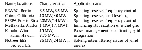
BEWAG, Berlin 8.5 MW/8.5 MW h Spinning reserve, frequency control Chino, California 10 MW/40 MW h Spinning reserve, load leveling PREPA, Puerto Rico 20MW/14 MW h Spinning reserve, frequency control Metlakatla, Alaska 1 MW/1.4 MW h Enhancing stabilization of island grid Kahuku Wind
Farm, Hawaii
15 MW/ 3.75 MW h
Power management, load firming, grid integration
Notrees EES project, U.S.
operating cost (80 $/kW/year) and an extra system required to ensure its operating temperature[72].
The NaS battery is considered as one of the most promising candidates for high power EES applications. Table 5 lists some NaS battery facilities with their applications. The research and development focuses are mainly on enhancing the cell perfor-mance indices and decreasing/eliminating the high temperature operating constrains. For instance, Sumitomo Electric Industries and Kyoto University developed a low temperature sodium related battery – the novel sodium-containing material can be melted at 330 K[84]. The inventor claimed that the new battery can achieve an energy density as high as 290 W h/L[84]. In addition, a part of the outcome to the ‘‘Wind to Battery’’ project led by Xcel Energy was recently presented in [83], mainly on the field results and analyses quantifying the ability and the value of NaS battery EES toward wind generation integration support[15,83].
3.4.4. Nickel–cadmium (NiCd) batteries
A NiCd battery uses nickel hydroxide and metallic cadmium as the two electrodes and an aqueous alkali solution as the electro-lyte. It normally has relatively high robust reliabilities and low maintenance requirements. The weaknesses of NiCd batteries are: cadmium and nickel are toxic heavy metals, resulting in envi-ronmental hazards [9,85]; the battery suffers from the memory effect – the maximum capacity can be dramatically decreased if the battery is repeatedly recharged after being only partially dis-charged[86].
To date there have been very few commercial successes using NiCd batteries for utility-scale EES applications. One example is at Golden Valley, Alaska, in the US[77]. This NiCd facility was offi-cially put into operation in 2003 by Golden Valley Electric Associ-ation. It offers services in spinning reserve, power supply and compensation to an ‘‘electrical island system’’ due to the geo-graphic restrictions, i.e. remote areas[77,87]. The system has the ability to deliver the rated power at 27 MW for 15 min or 40 MW for 7 min, and the efficiency is in the range of 72–78% with the operating temperature at 233–323 K[77,87,88]. The local cold temperature was the primary driving force behind the choice of the NiCd battery. It was reported that the NiCd technology for utility-scale EES applications was not pursued further after the Golden Valley installation[8,77]. It seems unlikely that NiCd batteries will be heavily used for future large-scale EES projects.
3.4.5. Other candidates of battery energy storage
The Nickel–metal Hydride (NiMH) battery is similar to the NiCd battery except that a hydrogen-absorbing alloy is used as the electrode instead of cadmium. It has moderate specific energy (70–100 W h/kg) and relatively high energy density (170– 420 W h/L), significantly better than those of the NiCd battery
[89–92]. Other advantages of NiMH batteries over NiCd batteries include a reduced ‘‘memory effect’’ and they are more environmen-tal friendly. NiMH batteries have the longer cycle life in compari-son with Li-ion batteries[89]. The NiMH battery has a wealth of applications from portable products to HEVs & EVs and potential industrial standby applications, such as UPS devices [89,90,93].
However, the significant barrier for EES applications is the high rate of self-discharge, losing5–20% of its capacity within the first 24 h after fully charging[89–91]. It is also sensitive to deep cycling – the performance decreases after a few hundreds full cycles
[89–92].
The technology of sodium nickel chloride battery (also known as ZEBRA battery) is similar to that of the NaS battery. The ZEBRA battery has moderate specific energy (94–120 W h/kg), energy density (150 W h/L), specific power (150–170 W/kg), and a high operating temperature (523–623 K) [4,94–98]. The advantages consist of good pulse power capability, cell maintenance free, very little self-discharge and relatively high cycle life. This battery tech-nology has been applied in EV demonstrations and Rolls Royce has used it to replace lead–acid in surface ships applications[97]. GE launched Durathon sodium–metal halide battery for UPS and util-ity market, which can be considered as a continuing improvement on the ZEBRA technology[98]. A GE Durathon battery manufactur-ing facility in New York was officially opened in 2012 [98]. Recently, a new venture, FIAMM Energy Storage Solutions, also started to produce such batteries (named SoNick batteries) for sta-tionary storage applications[99]. With regard to its drawback, the battery takes 12–15 h to heat up after it has been solidified (frozen)
[94]. In addition, only a few companies have been involved in the development of this technology and have produced this type of battery, which may limit its potential[4,94,98].
3.5. Flow Battery Energy Storage (FBES)
A flow battery stores energy in two soluble redox couples con-tained in external liquid electrolyte tanks. These electrolytes can be pumped from the tanks to the cell stack which consists of two electrolyte flow compartments separated by ion selective mem-branes. The operation is based on reduction-oxidation reactions of the electrolyte solutions. During the charging phase, one electro-lyte is oxidized at the anode and another electroelectro-lyte is reduced at the cathode, and the electrical energy is converted to the electro-lyte chemical energy. The above process is reversed during the dis-charging phase.
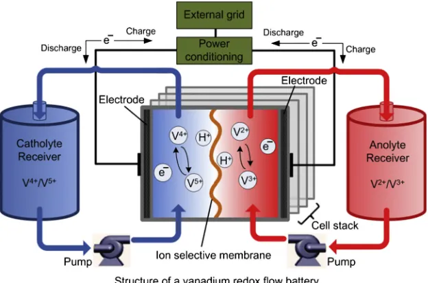
Flow batteries can be classified into the categories of redox flow batteries and hybrid flow batteries, depending on whether all elec-troactive components can be dissolved in the electrolyte. Fig. 8
[image:9.595.31.553.684.753.2]shows a schematic diagram of a vanadium redox flow battery sys-tem. A crucial advantage of FBES is that the power of a FBES system is independent of its storage capacity. The power of the FBES sys-tem is determined by the size of the electrodes and the number of cells in the stack; whereas the storage capacity is determined by the concentration and the amount of electrolyte[26,100,101]. Also, the very small self-discharge is an inherent strength of the FBES system due to the electrolytes being stored in separate sealed tanks[4,13]. Drawbacks of flow batteries include low performance resulting from non-uniform pressure drops and the reactant mass transfer limitation, relatively high manufacturing costs and more complicated system requirements compared to traditional batter-ies[102,103].
Table 5
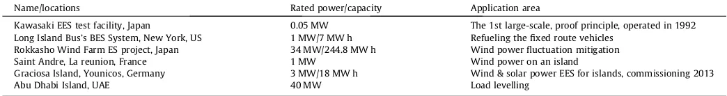
Selected sodium-sulfur battery energy storage facilities[77,81–83].
Name/locations Rated power/capacity Application area
Kawasaki EES test facility, Japan 0.05 MW The 1st large-scale, proof principle, operated in 1992
Long Island Bus’s BES System, New York, US 1 MW/7 MW h Refueling the fixed route vehicles
Rokkasho Wind Farm ES project, Japan 34 MW/244.8 MW h Wind power fluctuation mitigation
Saint Andre, La reunion, France 1 MW Wind power on an island
Graciosa Island, Younicos, Germany 3 MW/18 MW h Wind & solar power EES for islands, commissioning 2013
FBES facilities have been demonstrated at a few hundred kW and even multi-MW levels, and there are not many commercially available FBES systems at present[4,19,104]. The current research activities undertaken cover: low-cost, efficient and reliable elec-trodes; highly permselective and durable membranes; power and energy management of large-scale FBES systems, etc. Some types of flow battery technologies have been used or can potentially be used for utility EES applications, including vanadium redox, zinc bromine and polysulfide bromine, which are described in the fol-lowing three subsections.
3.5.1. Vanadium Redox Flow Battery (VRB)
The VRB is one of the most mature flow battery systems[4,87]. The VRB stores energy by using vanadium redox couples (V2+/V3+
andV4+/V5+) in two electrolyte tanks (Fig. 8). VRBs exploit the vana-dium in these four oxidation states which makes the flow battery have only one active element in both anolyte and catholyte
[100]. During the charge/discharge cycles, H+ions are exchanged through the ion selective membrane. The chemical reaction is:
V4+
MV5++ e and V3++ e
MV2+; the cell voltage is
1.4 V
[100,102].
VRBs have quick responses (faster than 0.001 s) and can operate for 10,000–16,000+ cycles[18,105]. They have relatively high effi-ciencies, up to85%[100,105]. Manufacturers can design VRBs to provide continuous power (discharge duration time 24+ hours)
[image:10.595.145.457.529.735.2][4,106]. Although VRBs now tends to expand their range of appli-cations by enhancing the physical scale, there are some technical challenges that need to be solved, for instance, low electrolyte sta-bility and solusta-bility leading to low quality of energy density
[107,108]. Also, the relatively high operating cost needs to be fur-ther reduced[103].
VRBs can be used in a large number of applications, mainly including enhancing power quality used for stationary applications and UPS devices, improving load levelling and power security, sup-porting the intermittent nature of renewable energy-based power generation. Some VRB facilities worldwide are introduced in
Table 6. Currently, two projects on VRBs have been funded with a combined cost of £1.2 million in the UK. One project has been developed by Scottish Power, the University of Southampton and others, which planned to test a 100 kW redox flow battery for util-ity EES[6]. Another VRB energy storage system project has been
developed by C-Tech Innovation Ltd, E.ON UK plc. and other insti-tutes, which is especially for storing surplus energy from renew-able energy sources [108]. Both of these two projects intend to be developed to a larger scale after the successes of initial small-scale trials[6,109].
3.5.2. Zinc Bromine (ZnBr) flow battery
ZnBr flow batteries belong to the hybrid flow batteries category. In a ZnBr battery, two aqueous electrolyte solutions contain the reactive components, which are based on zinc and bromine ele-ments, stored in two external tanks. During the charging/discharg-ing phases, these two electrolyte solutions flow through the cell stack consisting of carbon-plastic composite electrodes with com-partments. Thus the reversible electrochemical reactions occur in these electrolytic cells. The corresponding chemical reactions are: 2Br
MBr2+ 2eand Zn2++ 2eMZn[4,102].
The ZnBr flow battery has relatively high energy density (30– 65 W h/L) and cell voltage (1.8 V)[4,26]. It also has deep discharge capability and good reversibility[19,102]. Module sizes vary from 3 kW to 500 kW, with estimated lifetimes of 10-20 years and dis-charge durations of up to 10 h[4,112,113]. The disadvantages of the ZnBr battery are: material corrosion, dendrite formation and relatively low cycle efficiencies (around 65–75%) compared to traditional batteries, which can limit its applications
[4,114,115]. Furthermore, ZnBr batteries normally operate in a nar-row temperature range[102,116].
Utility EES applications using ZnBr batteries are in the early stage of demonstration/commercialization. ZBB Energy Corpora-tion and Premium Power CorporaCorpora-tion have developed this technol-ogy for commercial purposes (50 kW h, recently tested up to
2 MW)[14]. The firm RedFlow in Australia successfully commer-cialized a fully functional ZnBr module product, named ZBM, which delivers up to 3 kW of continuous power (5 kW peak) and up to 8 kW h of energy; the company claimed that it can achieve up to 80% DC-DC max net energy efficiency [113]. In 2011, U.S. electric utilities conducted early trials of 0.5 MW/2.8 MW h trans-portable ZnBr systems for grid support and reliability[117]. In the same year, Sacramento Municipal Utility District (SMUD) planned to demonstrate a 1 MW ZnBr flow battery system for multi EES applications[100,118]. A relevant project, named ‘‘flow batteries
for grid scale energy storage’’, has been implemented by Lawrence Berkeley National Laboratory in Berkeley, U.S.[100].
3.5.3. Polysulfide Bromine (PSB) flow battery
A PSB system uses sodium bromide and sodium polysulphide as salt solution electrolytes. The chemical reactions are: 3BrMBr
3
+ 2e and 2S
2 2
MS4+ 2e [4,19]. The significant advantages of
PSB systems are: the materials of two electrolytes are abundant and highly soluble in aqueous electrolytes, and they are also cost-effective[19]. The voltage generated across the membrane is
1.5 V; the PSB system has a fast response time, reacting within 20 ms [4,105]. PSBs have a wide range of potential application areas, especially for power system frequency control and voltage control due to their fast response characteristic. Because bromine and sodium sulfate crystals are produced during the chemical reac-tions, this may result in environmental issues.
Several PSB systems have been demonstrated at multi-kW scales. For instance, a 100 kW stack using PSB technology had been built by the UK Company Innogy, with a net efficiency of75%
[image:11.595.30.562.87.156.2][104]. Concerning large-scale PSB facility deployment, Regenesys Technologies had tried to build a 15 MW/120 MW h energy storage plant at a power station in the UK; another demonstration plant to be located at Tennessee Valley in the U.S. was designed with a 12 MW/120 MW h capacity for EES to support a wind power plant operation[4]. However, due to engineering difficulties and finan-cial constraints, the construction of these two large storage plants was ceased and the demonstration plants were uncompleted
[77,104,119]. Thus the PSB technology for large-scale EES applica-tions still needs practical experience.
3.6. Capacitor and supercapacitor
A capacitor is composed of at least two electrical conductors (normally made of metal foils) separated by a thin layer of insula-tor (normally made of ceramic, glass or a plastic film). When a capacitor is charged, energy is stored in the dielectric material in an electrostatic field[4,120,121]. Its maximum operating voltage is dependent on the breakdown characteristics of the dielectric material. Capacitors are appropriate for storing small quantities of electrical energy and conducting a varying voltage; they have a higher power density and shorter charging time compared to conventional batteries[70]. However, they have limited capacity, relatively low energy density and high energy dissipation due to the high self-discharge losses [4,120–122]. According to these characteristics, capacitors can be used for some power quality applications, such as high voltage power correction, smoothing the output of power supplies, bridging and energy recovery in mass transit systems.
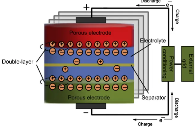
Supercapacitors, also named electric double-layer capacitors or ultracapacitors, contain two conductor electrodes, an electrolyte and a porous membrane separator (refer toFig. 9)[13]. Due to their structures, supercapacitors can have both the characteristics of tra-ditional capacitors and electrochemical batteries. The energy is stored in the form of static charge on the surfaces between the electrolyte and the two conductor electrodes. The supercapacitors with high-performance are based on nano materials to increase electrode surface area for enhancing the capacitance.
[image:11.595.134.450.532.739.2]The power and energy densities of supercapacitors are between those of rechargeable batteries and traditional capacitors Table 6
Selected vanadium redox flow battery energy storage facilities[67,105,107,110,111].
Name/locations Power/capacity Application area
Edison VRB EES facility, Italy 5 kW, 25 kW h Telecommunications back-up application
Wind power EES facility King Island, Australia 200 kW, 800 kW h Integrated wind power, foil fuel energy with EES
Wind Farm EES project, Ireland 2 MW, 12 MW h Wind power fluctuation mitigation, grid integration
VRB EES facility installed by SEI, Japan 1.5 MW, 3 MW h Power quality application
VRB facility by PacifiCorp, Utah, U.S. 250 kW, 2 MW h Peak power, voltage support, load shifting
VRB EES system build by SEI, Japan 500 kW, 5 MW h Peak shaving, voltage support
[20,123,124]. The most important features of supercapacitors are their long cycling times, more than 1105cycles, and high cycle
efficiency,84–97%[4,66]. However, the daily self-discharge rate of supercapacitors is high,5–40%, and the capital cost is also high, in excess of 6000 $/kW h[4,10,13,125]. Thus supercapacitors are well suited for short-term storage applications but not for large-scale and long-term EES. Typical applications in power quality consist of pulse power, hold-up/bridging power to equipment, solenoid and valve actuation in factories, UPS devices, etc. There are a number of manufacturers producing supercapacitors world-wide (refer toTable 7).
Research and development in supercapacitors has been very active in recent years. Some recent good quality reviews have focused on the recent development of materials for chemical capacitive energy storage, such as an overview of carbon materials for super-capacitors is given in[24]and an overview of graphene-based electrodes can be found in[25]. To be more specific, a new composite material formed by dispersing ultra-small silicon nano-particles in polyaniline was developed as the electrode material for supercapacitors[128]. The integration of a short-term supercapac-itor EES device in a doubly fed induction generator has been studied in order to smooth the fast wind-induced power variations
[129]. One UK EPSRC funded project aiming to develop high-performance supercapacitors with enhanced energy density had been implemented. The prototype had been tested for designing an effective and sustainable power system. Some achievements of this project were published in 2013[130].
3.7. Superconducting Magnetic Energy Storage (SMES)
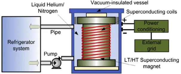
A typical SMES system is composed of three main components which include: a superconducting coil unit, a power conditioning subsystem, and a refrigeration and vacuum subsystem [13,109, 131]. The SMES system stores electrical energy in the magnetic
field generated by the Direct Current (DC) in the superconducting coil which has been cryogenically cooled to a temperature below its superconducting critical temperature. In general, when current passes through a coil, the electrical energy will be dissipated as heat due to the resistance of the wire; however, if the coil is made from a superconducting material, such as mercury or vanadium, under its superconducting state (normally at a very low tempera-ture), zero resistance occurs and the electrical energy can be stored with almost no losses. One commonly used superconducting mate-rial is Niobium–Titanium which has a superconducting critical temperature of 9.2 K[4,132]. In the discharging phase, the SMES system can release the stored electrical energy back to the Alternating Current (AC) system, by a connected power converter module. The magnitude of stored energy is determined by the self-inductance of coil and the current flowing through it[133]. A simplified structure of a SMES system is illustrated inFig. 10.
Superconducting coils can be classified into two groups: Low Temperature Superconducting (LTS) coils, working at 5 K, and High Temperature Superconducting (HTS) coils, working at70 K
[13,131]. The LTS-SMES technology is more mature and commer-cially available while the HTS-SMES is currently in the develop-ment stage. SMES devices in the range of 0.1–10 MW have been used commercially; while SMES systems with 100 MW h could be available in the next decade.
The features of SMES include relatively high power density (up to4000 W/L), fast response time (millisecond level), very quick full discharge time (less than 1 min), high cycle efficiency (95– 98%) and long lifetime (up to30 years)[4,66,114,134]. In contrast to rechargeable batteries, SMES devices are capable of discharging near to the totality of the stored energy with little degradation after thousands of full cycles. The drawbacks are that they have high capital cost (up to 10,000 $/kW h, 7200 $/kW), high daily self-discharge (10–15%) and a negative environmental impact due to the strong magnetic field[4,14,114]. Moreover, the coil is sensitive to small temperature variations which can cause the loss of energy. From the above, SMES is suitable for short-term storage in power and energy system applications and it is expected to have an important role in the increased use of intermittent renewable energy [131]. Table 8shows selected SMES facilities with their application fields.
[image:12.595.151.454.614.739.2]Recently, considerable research and development effort has been made: (1) to reduce the costs of superconducting coils and related refrigeration systems; (2) to develop HTS coil materials which are less cryogenically sensitive [14,109,131]. Since 2011, SuperPower Inc., in partnership with ABB Inc., Brookhaven national laboratory and the Texas center for superconductivity at the Uni-versity of Houston has been developing an advanced SMES demon-strator 20 kW ultra-high field SMES system with a capacity up to 2 MJ [135]. This demonstration project aims to pave the way of grid-scale SMES technology for the U.S. electric grid operation Table 7
Selected manufacturers of supercapacitors for utility applications[20,67,126,127].
Device/Company name Country Technical information
Super capacitor, CAP-XX
Australia Single cell 2.3–2.9 V, up to2.4 F, 233-358 K
Gold capacitor, Panasonic
Japan Single cell 2.3–5.5 V, 0.1–2000 F
Ultracapacitor/ Boostcap, Maxwell
U.S. Single cell 2.2–2.7 V, 1–3000 F, UPS, pulse, transportation
Supercapacitor, NEC Japan 3.5–12 V, 0.01–6.5 F, power quality application
Supercapacitor, Siemens
Germany 21 MJ/5.7 W h, 2600 F, metro distribution net application Supercapacitor, TVA
company
U.S. 200 kW, supporting the start of high power dc machines
and for the integration of renewable sources. The University of Bath in the UK continuously focus on SMES technology develop-ment and a relevant on-going project funded by the UK EPSRC aims to investigate HTS-SMES as part of hybrid EES systems for renew-able energy micro-grids[136,137].
3.8. Solar fuels
[image:13.595.29.562.85.164.2]Solar fuel is a relatively new technology to EES. Approaches to produce solar fuels include: (1) natural photosynthesis; (2) artifi-cial photosynthesis; (3) thermochemical approaches[4,139,140]. A number of fuels can be produced by solar energy, such as solar hydrogen, carbon-based fuels, and solar chemical heat pipe
[4,140–143]. These fuels can be stored and subsequently provide the basis for later electricity generation.
For the first two approaches to produce solar fuels, solar energy is captured via photosynthesis and then stored in chemical bonds, i.e., the sunlight is used to convert water and/or carbon dioxide into oxygen and other materials[144].Fig. 11shows a comparison of natural and artificial photosynthesis. The artificial system for water-splitting catalysts generally relies on scarce elements, e.g., Ruthenium (Ru), Palladium (Pd) and Rhenium (Re)[140,145]. For example, sunlight can be captured by Ruthenium (Ru) as a catalyst, and electrons moves from the donor (marked as ‘‘D’’) to the accep-tor (Fig. 11)[140,145].
The thermochemical approach uses thermal processes for solar fuels production, which involve the generation of very high tem-peratures in a closed environment to split water into its constitu-ent parts [4]. Thus this method is more dependent on strong sunlight compared to the other two[144,146]. After the solar radi-ant energy is concentrated by heliostats, an endothermic chemical transformation is carried out in a reaction vessel. The reaction pro-duces hydrogen and/or carbon monoxide and/or other materials
[142,143,147].
[image:13.595.144.442.615.739.2]Solar fuel technology is currently at the development stage. The power rating of solar fuels is potentially up to 20 MW and the spe-cific energy estimate is from 800 W h/kg to 100,000 W h/kg
[4,148]. The storage duration can range from a few hours to several months[4]. One drawback of artificial photosynthesis is that the
water-splitting catalysts normally depend on scarce, expensive elements[145]. Another disadvantage is that solar fuel facilities need a large area to place devices to concentrate sunlight, espe-cially when using the thermochemical approach to produce solar fuels.
Research in solar fuels has recently undergone substantial advances, making it possible for it to become cost-effective for util-ity EES applications in the near future. There are on-going research projects in the U.S., the Netherlands, South Korea, Singapore, Japan and China. In the US, there are several organizations focusing on this area, such as Energy Innovation Hub at DoE, the MIT spin-out Sun Catalytix and the Princeton University spin-spin-out Liquid Light. The ‘‘Towards BioSolar Cells’’ research programme has focused on increasing the photosynthetic efficiency and creating solar collectors[140,149]. Concerning the issue of the reliance on scarce and expensive elements, one important breakthrough in the development of using earth-abundant, relatively cheap cata-lysts (e.g. cobalt and phosphate) and silicon-based semiconductors for the water-splitting process has been recently reported by the Nocera’s team from MIT [150,151]. Asia’s pioneering solar fuel research laboratory at Nanyang Technological University of Singa-pore has also made effort on the investigation of affordable approaches to extract large amounts of hydrogen from water using sunlight for engineering applications[151,152].
3.9. Hydrogen storage and fuel cell
Hydrogen energy storage systems use two separate processes for storing energy and producing electricity (refer toFig. 12). The use of a water electrolysis unit is a common way to produce hydro-gen which can be stored in high pressure containers and/or trans-mitted by pipelines for later use (Fig. 12)[8,13]. When using the stored hydrogen for electricity generation, the fuel cell (also known as regenerative fuel cell) is adopted, which is the key technology in hydrogen EES.
Fuel cells can convert chemical energy in hydrogen (or hydro-gen-rich fuel) and oxygen (from air) to electricity[8,13,153]. The overall reaction is: 2H2+ O2?2H2O + energy[154]. Electrical and
heat energy are released during the process (Fig. 12). Depending Table 8
Some projects of superconducting magnetic energy storage[67,131,133,138].
Locations/organizations Technical data Features/applications
Proof principle, tested in a grid in Germany 5 KJ, 2 s to max 100 A at 25 K World first significant HTS-SMES, by ASC
Nosoo power station in Japan 10 MW Improve system stability and power quality
Upper Wisconsin by American Transmission 3 MW/0.83 kW h, each 8 MV A Power quality application reactive power support
Bruker EST in Germany 2 MJ High temperature superconductors
Korea Electric Power Corporation, Hyundai 3 MJ, 750 kV A Improving power supply quality for sensitive loads
Chubu Electric Power Co. in Japan 7.3 MJ/5 MW and 1 MJ Provide comparison to transient voltage
University of Houston, SuperPower & others 20 kW, up to 2 MJ class UHF-SMES, voltage distribution
on the choice of fuel and electrolyte, there are six major groups of fuel cells, which are: Alkaline Fuel Cell (AFC), Phosphoric Acid Fuel Cell (PAFC), Solid Oxide Fuel Cell (SOFC), Molten Carbonate Fuel Cell (MCFC), Proton Exchange Membrane Fuel Cell (PEMFC) and Direct Methanol Fuel Cell (DMFC) [154]. Their chemical reactions and application fields are listed inTable 9.
[image:14.595.152.451.62.206.2]In general, the electricity generation by using fuel cells is quieter, produces less pollution and is more efficient than the fossil fuel combustion approach[156]. Other features include easy scal-ing (potential from 1 kW to hundreds of MW) and compact design
[image:14.595.41.293.625.754.2][153,157]. Fuel cell systems combined with hydrogen production and storage can provide stationary or distributed power (primary electrical power, heating/cooling or backup power) and transporta-tion power (potentially replacing fossil fuels for vehicles)
[153,154]. Such hydrogen EES systems can offer capacity and power independence in energy production, storage and usage, due to the separate processes. It should be noted that the disposal of exhaust fuel cells must consider degradation and recycling while toxic metals are used as electrodes or catalysts. Many of the rele-vant aspects and approaches have been under investigation
[158,159]. For instance, palladium in catalysts of fuel cells can be reprocessed into other products in theory[159].
Currently, hydrogen EES with fuel cell technology is in the development and demonstration stage. Stationary power applica-tions are relatively mature. In 2012 nearly 80% of total investment in the global fuel cell industry was made by the U.S. companies
[153]. Cost reduction and durability verification/improvement are essential to deploy this technology in large-scale EES applications
[109]. Some research or demonstration projects are in place and on-going across the world. The world’s first utility-scale test of a stand-alone renewable energy system integrated with hydrogen storage and fuel cells was installed in Norway, which delivered power with required quality and high reliability[157]. One of the
world’s largest biogas fuel cell power plants was launched in 2012 in California (2.8 MW), which converts biogas into electricity and usable high-quality heat[160]. In 2013, the US Naval Air War-fare Center Weapons Division in California successfully tested a novel 5 kW trailer-mounted regenerative fuel cell system to use solar power to produce hydrogen with fuel cells [161]. Since 2013, McPhy and Enertrag AG in Germany have worked jointly to develop economic wind-hydrogen solutions for EES and for trans-portation fuel cell applications [162]. Currently, the on-going hydrogen storage and fuel cell relevant projects include IdealHy (the Netherlands), RE4CELL (Spain), Sapphire (Norway), SmartCat (France), etc.
3.10. Thermal Energy Storage (TES)
TES encompasses a variety of technologies that store available heat energy using different approaches in insulated repositories
[6,26]. A TES system normally consists of a storage medium in a reservoir/tank, a packaged chiller or built-up refrigeration system, piping, pump(s), and controls. Based on the range of operating temperature, TES can be classified into two groups: low-tempera-ture TES (consisting of aquiferous low-temperalow-tempera-ture TES and cryo-genic energy storage) and high- temperature TES (including latent (fusion) heat TES, sensible heat TES and concrete thermal storage) [4,163–166]. Aquiferous low-temperature TES normally uses water cooled/iced and reheating processes, which is more suitable for peak shaving and industrial cooling loads[4]. Cryo-genic energy storage employs a cryogen (such as liquid nitrogen or liquid air) to achieve the electrical and thermal energy conver-sion. For instance, Liquid Air Energy Storage (LAES) is attracting attention due to the high expansion ratio from the liquid state to the gaseous state and the high power densities of liquid air com-pared to that of gaseous state of air. Latent heat TES employs Phase Change Materials (PCMs) as the storage media and uses the energy absorption or emission in liquid-solid transition of these PCMs at constant temperature. Concrete thermal storage utilizes concrete or castable ceramics to store heat energy, normally supported by synthetic oil as a heat transfer fluid. The above TES technologies have different features with various applications. For instance, latent heat storage can provide a relatively high storage density with a small dimension reservoir, thus the use of this technology in buildings receives attention[21]. In addition, cryogenic energy storage is expected to be used for future grid power management. The TES system can store large quantities of energy without any major hazards and its daily self-discharge loss is small (0.05–1%); the reservoir offers good energy density and specific energy (80–500 W h/L, 80–250 W h/kg) and the system is economically viable with relatively low capital cost (3–60 $/kW h) [4,10,166– 168]. However, the cycle efficiency of TES systems is normally low (30–60%) [4]. TES has been used in a wide spectrum of Fig. 12.Topology of hydrogen storage and fuel cell.
Table 9
Chemical reactions of main fuel cells[154,155].
Fuel cell Type
Chemical reactions at anodes and cathodes
Applications
AFC 2H2+ 4OH?4H2O + 4e Military, space applications
O2+ 2H2O + 4e?4OH
PAFC 2H2?4H++ 4e Distributed generation
O2+ 4H++ 4e?H2O
SOFC O2(S) + H
2(g)?H2O(g) + 2e Utility EES, distributed
generation 1/2O2(g) + 2e?O2(s)
MCFC H2O + CO32?H2O + CO2+ 2e Electric utility EES,
distributed generation 2H2+ 4OH?4H2O + 4e
PEMFC H2(g)?2H++ 2e Backup power, small
distributed generation 1/2O2(g) + 2H++ 2e?H2O
DMFC CH3OH + H2O?CO2+ 6H++ 6e Transportation, portable
applications, such as load shifting and electricity generation for heat engine cycles.
With particular focus on using TES for power system and grid applications, there are many active research projects worldwide and, in addition, numerous demonstration projects are built, under construction or planned. The UK based company Highview Power Storage designed and assembled a pilot LAES facility (300 kW/ 2.5 MW h storage capacity) which has been in operation at Scottish and Southern Energy’s 80 MW biomass plant since 2010[168,169]. In February 2014, this firm has been awarded £8 million funding from the UK government for a 5 MW/15 MW h demonstration LAES project; the designed LAES system will be alongside one land-fill gas generation plant in the UK[169]. A TES system in an office building was built by a joint U.S. and China demonstration project in Beijing, which can reduce peak electric energy consumption of 6100 kW h per month[170]. A new central energy plant including an ice-based TES system is being built in South Florida. The com-pletely built plant will have a total capacity of 11,500 tons of chilled water with 68,000 ton-hour of TES[170]. A 15 MW com-mercial power plant, named ‘‘Solar Tres Power Tower’’, is being built in Spain by Torresol Energy, and it uses molten salt as the working fluid to store heat energy[165]. A wind power generation system combined with a sensible heat storage facility had been proposed (Fig. 13)[165]. The electrical energy from wind power is used to heat a bulk storage material; the heat energy is recovered to produce water vapor which in turn drives a turbo-alternator to generate electricity. A detailed study of load shifting of nuclear power plants by using cryogenic energy storage technol-ogy was recently reported in[171]. A UKERC funded project, ‘‘the future role of TES in the UK energy system’’, has investigated the potential for, and limitations of, the role of TES in the transition to a sustainable low carbon energy supply system; the project has also studied the suitability of TES in managing energy genera-tion and distribugenera-tion systems with large-scale penetragenera-tion[6].
3.11. Hybrid electrical energy storage
[image:15.595.136.450.66.218.2]Hybrid EES refers to the integration of at least two different EES technologies into one system or application. Advantages of each EES technology can be utilized to achieve specific requirements, meet harsh working environments, optimize the whole system performance or improve the cycle efficiency. For example, the first large pilot power plant (ADELE) utilizes CAES and TES technologies for enhancing the efficiency and avoiding fossil fuel consumption
[42,43]. The combination of supercapacitor and battery technolo-gies can offer relatively large storage capacity and very fast charge/discharge rates. One project in the theme of a hybrid sup-ercapacitor-battery system, funded by E.ON, was completed in
UK and a corresponding demonstration system was developed
[6]. Another project funded by UK EPSRC, named ‘‘Ultra battery fea-sibility - investigation into the combined battery- supercapacitor for hybrid electric vehicle applications’’, was completed in 2012, and some achievements were recently published in [172]. Researchers in Japan High Energy Accelerator Research Organiza-tion, Tohoku University and others have designed a back-up sys-tem for renewable energy power generation, which combines a liquid hydrogen refrigeration-based SMES system with a hydro-gen-fuel cell system[109,173].
4. Comparison and evaluation of electrical energy storage technologies
It is well recognized that no single EES technology can meet the requirements for all power system applications. Comprehensive analysis of different EES technologies is conducted and Tables 10–12provide the matrices to clearly show the positions of differ-ent EES performance and characteristics. The selection of represen-tative matrices inTables 10–12is derived with consideration of the focuses in both academic research and industry application areas, which is drawn from the comprehensive literature review in this paper. The selection of EES indices also relies on the assessment in the characteristics of different EES options against the require-ments of power system applications, which will be discussed in Section5.
Size of storage devices is an important factor for many applica-tions.Fig. 14shows the comparison of power density and energy density of different EES technologies. For a given amount of energy, the higher the power and energy densities are, the smaller the vol-ume of the required energy storage system will be. InFig. 14, the highly compact technologies suitable for volume-limited applica-tions can be found at the top right corner and the large volume consuming storage systems are located at the bottom left corner. It can be seen that most batteries, flywheel and fuel cells have rel-atively moderate energy densities and power densities. PHS and CAES have lower densities, thus they are mainly used in stationary EES and require large reservoirs for grid scale applications. Sup-ercapacitors and capacitors have very high power densities but low energy densities. The densities of flow batteries are commonly lower than those of conventional batteries. The Li-ion battery has both a high energy density and a high power density, which leads to widespread uses in portable devices and promising potential in transportation and other small-scale EES applications.
![Fig. 1. Electrical energy storage technologies with challenges to the UK energy systems [4,6,7–9].](https://thumb-us.123doks.com/thumbv2/123dok_us/9507376.456136/3.595.106.476.498.736/fig-electrical-energy-storage-technologies-challenges-energy-systems.webp)