ISSN: 1682-3915
© Medwell Journals, 2008
Corresponding Author: A. Subramani, Department of M.C.A, K.S.R. College of Engineering, Tiruchengode-637 215, Namakkal District, Tamilnadu, India
A Study of Fairness for ATM ABR Service Based on Doubly
Finite Queue using MSVDR Algorithm
A. Subramani and A. Krishnan
1 2
Department of M.C.A, K.S.R. College of Engineering, Tiruchengode-637 215, 1
Namakkal District, Tamilnadu, India
K.S. Rangasamy College of Technology, Tiruchengode-637 215, 2
Namakkal District, Tamilnadu, India
Abstract: A general goal of the Asynchronous Transfer Mode (ATM) network is to support connections a cross Local-Area Networks (LANs), Metropolitan Area Networks (MANs) and Wide Area Networks (WANs). However, in Available Bit Rate (ABR) service, different treatments are offered according to different Round Trip Times (RTTs) of connections. To improve the above unfairness, this study presents Doubly Finite Queue mechanism and Multi Source Virtual Dynamic Routing Algorithm, in which 3 reference parameters for cell delay are defined and reflect on the messages of Resource Management (RM) cells. To evaluate our mechanism, we execute simulations on a simple ATM network model where multiple connections and background traffic with different RTTs share the bandwidth of a bottleneck link. The simulation results, based on good throughput and efficiency, clearly show that the mechanism improves the fairness among multiple connections, although the considered implementation of ABR transfer capacity is simple.
Key words: ATM, queue management, RTT, ABR, routing algorithm
INTRODUCTION ABR service cannot be predicted; however, to achieve ATM has been adopted for B-ISDN as a networking met. In ABR service, bandwidth is not statically allocated. protocol with a potential to support applications with Instead, the Peak Cell Rate (PCR) and Minimum Cell Rate distinct tolerances for delay, jitter and cell loss. To (MCR) are specified. The transmission rate of each address this spectrum of needs, the ATM Forum has connection is controlled between PCR and MCR, based defined a family of service categories (ATM Forum, 1999). on feedback messages from the network by using C Constant Bit Rate (CBR) service is used by controls are defined by the ATM Forum (1999). From one
connections that request a fixed amount of of them, we adopt Relative Rate Marking (RRM).
bandwidth. Because RM cells are transmitted through
C Variable Bit Rate (VBR) service is intended for connections between sources and destinations, applications which have bursty traffic characteristics, connections with shorter RTI’s can modify their with precisely defined requirements for throughputs transmission rate much faster than those with longer
and delays. RTTs. This destroys the fairness among connections
C Unspecified Bit Rate (UBR) service is intended for (Bianco, 1994; Macro, 1995). The definition of fairness in applications with minimal service requirement. this study is to share equally the available bandwidth C Available Bit Rate (ABR) service is suitable for between all the connections or, in other words, identical supporting highly bursty data applications on ATM bandwidth should be provided to connections with
networks. identical requirements.
With ABR service, sources are expected to have the ABR service, this study proposes a DFQ and MSVDR ability to decrease or increase their transmission rate if the algorithm. Finally, we execute simulation experiments on network requires them to do so, except when the a simple ATM network model. We choose TCP as the connections are established. Most traffic parameters of higher Protocol upon ATM ABR service, since TCP is the good throughput, certain cell loss requirements must be
Resource Management (RM) cells. Several feedback
most widely used transport protocol in both LAN and WAN. In our simulation model, multiple connections with different RTTs share the bandwidth of a bottleneck link with background traffic. From the comparisons based on the good throughput-the effective throughput obtained by receivers and the efficiency between ABR DRR and ABR DFQ mechanisms, the simulation results clearly show that ABR DFQ mechanism has improved the fairness among multiple connections, although the considered implementation of the ABR transfer capacity is quite simple.
In addition, the ABR congestion management specification accommodates at least 2 different modes in which switches in the network may operate. The source/destination policies (the main focus of the specification) are designed to smoothly operate with any intermingling of the 2 types of switches in the network-these are the explicit forward congestion indication (EFCI) and explicit rate (ER) switches. EFCI switches use a single bit to communicate congestion (Ramakrishnan and Jain, 1990), when a queue threshold is exceeded. ER switches, on the other hand, compute a max-min fair rate (Charny et al., 1995; Charny and Ramakrishnan, 1996) and communicate this rate to the sources. The source and destination use a common ABR protocol to interface to networks with both types of switches. We show that the protocol correctly interoperates with both types of switches, using the formal specification.
ABR FLOW CONTROL MODEL
The ATM Forum Technical Committee has specified the ABR rate-based flow control in The ATM Forum Technical Committee (1996), Lengliz and Kamoun (2000). These specifications describe essentially, the source and the destination end-systems behavior; the constraints applicable to the switches were left implementation specific.
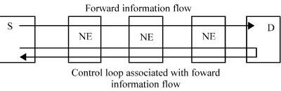
ABR flow control model: ABR flow control occurs between a sending end-system (source) and a receiving end-system (destination). Sources and destinations are connected via bidirectional connections. The forward direction is the direction from the source to the destination and the backward direction is the direction from the destination to the source. As shown in the Fig. 1, for the forward information flow from the source to the destination, there is a control loop consisting of 2 RM cell flows, one in the forward direction and the other in the backward direction.
[image:2.612.323.523.94.159.2]A source generates forward RM cells which are turned around by the destination and sent back to the source as backward RM cells. These backward RM cells carry feedback information provided by the network elements and/or the destination back to the source. This
Fig. 1: Source-destination ABR control loop
information is about the state of the network, like bandwidth availability, state of congestion and impending congestion.
An RM cell includes many fields (The ATM Forum Technical Committee, 1996). Among them we can mention:
DIR (DIRection): It indicates the direction of the cell, 0 for forward and 1 for backward.
Explicit rate (ER): This field is used to limit the source rate allowed cell rate (ACR) to a specific value. For each RM cell, ER is set by the source to a requested rate. It may be subsequently reduced by any network element in the path to a value that the element can sustain.
Current cell rate (CCR): It is set by the source to its current transmission rate ACR. The value of the CCR field remains unchanged during its round-trip propagation.
Congestion indication (CI): It allows a network element to indicate that there is congestion, so the source shall decrease its rate.
No increase (NI): It is used by a network element to indicate impending congestion and so to prevent a source from increasing its ACR. In contrast to CI, it does not imply any decrease of the source rate.
Source behavior: The following items summarize the source behavior of a connection:
C The source shall never send cells at a rate exceeding a dedicated source rate ACR. This cell rate is controlled by means of the dynamic generic cell rate algorithm (DGCRA). The ACR value fluctuates between 2 bounds, the minimum cell rate (MCR) and the peak cell rate (PCR), specified in the traffic contract.
C Before a source sends the first cell after connection setup, it shall set ACR to at most initial cell rate (ICR). The first cell sent shall be a forward RM cell. C After the first forward RM cell, cells shall be sent
according to the following order:
C At least a number of MRM cells have been sent C VS/VD. The switch may segment the ABR control and at least a time of TRM units has elapsed. loop using virtual source and destination. C A number of Nrm-1 cells have been sent. C A switch may generate a backward RM cell. It shall C The next cell shall be a backward RM cell if condition assign values to the different RM cell fields.
above is not met, if a backward RM Cell is waiting for
transmission and if either: PROPOSED MODEL
C No backward RM cell has been sent since the last
forward RM cell. Doubly finite queue algorithm: Let C be the capacity of a C No data cell is waiting for transmission. link and ( be the desired utilization at the link. The C When a backward RM cell is received with CI = 1, MSVDR presented in routers, at a router works as follows:
then ACR shall be reduced, if this reduction results
in a value below MCR, ACR shall be set to MCR. If C The router maintains a doubly finite queue whose this RM cell has both CI = 0 and NI = 0, then the ACR capacity C # C and whose buffer size is equal to the may be increased, to a rate no greater than PCR. If buffer size of the real queue. Upon each packet this RM cell has NI = 1, the ACR shall not be arrival, a fictitious packet is en queued in the Second
increased. queue if there is sufficient space in the buffer. If the
C When a backward RM cell is received and after ACR new packet overflows the Second queue buffer, then is adjusted according to the previous rule, ACR is set the packet is discarded in the second queue buffer to minimum (ACR, ER), but no lower than MCR. and the real packet is marked by setting its ECN bit or C When generating a forward RM cell, the source shall the real packet is dropped, depending upon the assign values to the various RM cell fields. congestion notification mechanism used by the C A source shall reset the bit EFCI on every data cell it router.
sends. C At each packet arrival, the second queue capacity is
Destination behavior: The following points make the equation:
summary of the destination behavior of a connection: C = "((c - 8) (2) C When a data cell is received, its EFCI indicator is where, 8is the arrival rate at the link. The rationale behind saved as the EFCI state of the connection. this is that marking has to be more aggressive when the C On receiving a forward RM cell, the destination shall link utilization exceeds the desired utilization and should turn it around to return to the source as a backward be less aggressive when the link utilization is below the RM cell (the bit DIR shall be changed). desired utilization. We now make the following C If the saved EFCI state is set, then the destination observations. No actual enqueueing or dequeuing of shall set CI=1 in the RM cell and the saved state packets is necessary in the second queue also, we just EFCI shall be reset. have to keep track of the second queue length. Equation C If the destination has internal congestion, it may 2 can be thought of as a token bucket where tokens are reduce the value of ER to whatever rate it can generated at rate "(C up to a maximum of C and depleted support and/or set CI=1 or NI=1. by each arrival by an amount equal to " times the size of C A destination may generate a backward RM cell the packet. Define
without having received a forward RM cell. It shall
assign values to the various RM cell fields. B = Buffer size.
Switch behavior: The switch behavior can be specified as t = Current time.
follows: b = Number of bytes in current packet.
C A switch shall implement at least one of the following
methods to control congestion at queuing points: Then, the following pseudo-code describes an C EFCI marking. The switch may set the EFCI state implementation of second queue in MSVDR scheme.
in the data cell headers.
C Relative Rate Marking. The switch may set CI = 1 Doubly finite queue algorithm pseudo code:
or NI = 1 in forward and/or backward RM cells. Arrival of cell k at time ta(k) C Explicit Rate Marking. The switch may reduce the Start If (TAT<t (k))
value of the ER field in forward and/or backward Then TAT<-t (k)
RM cells. If (TAT< QPT(k))
1
updated according to the following differential
1
s = Arrival time of previous packet.
AQ = Number of bytes currently in the second queue.
Then TAT<- (TAT+I), Confirming Cell k Step 1: Calculate Shortest Path from congested Switch to Else
Non Confirming Cell k Else
If ((TAT>t (k)+L) and( TAT > QPT(k)))a
Then Non Confirming Cell k Else
TAT <- (TAT +I) confirming Cell k
If Confirming Cell Size (S (k)) > Available Link a
Capacity (ALC) Then
If QTH =’00’
Then Cell k Normally Forwarded Else if QTH =’01’
Then if CPL=0 // Cell Obey available rate Then Store in PQ
PQ +S (k)a
Else Store in SQ SQ +S (k)a
Else if QTH=’11’
Then Call MSVDR algorithm
//To find alternative path to forward the confirming k cells Else if QTH=’10’
Discarding k Cell Else
Cell forward normally End if
On demand path selection: When a connection setup request arrives, it is the responsibility of the source node to choose a path that is most likely able to support the required QoS. The source node makes a routing decision based on its local knowledge of the network topology. As a result of the PNNI configuration, the knowledge base of a node contains full information about its own peer group, aggregated information about its parent group, more aggregated information about its grandparent group and so forth. Therefore, source routing to a destination node outside the peer group, of the source node is actually to find a path up the hierarchy to the level that source and destination nodes are in the same logical group.
Assume that a connection from the congestion node S to the destination node D is to be setup. The parent logical node of the congested node S and the destination node D at level i in the hierarchy is denoted as Si and Di. Let us consider the case where 2 QoS parameters need to be satisfied: bandwidth BW and segment-to-segment delay DY, which stand for the attribute and metric parameter types, respectively. The Multi-Source Dynamic Routing (MSVDR) decisions can be made in the following steps (Subramani and Krishnan, 2007).
Destination Node using Hierarchical Least Loaded Routing Algorithm.
Step 2: Send reroute information to destination with new source address, routing path and starting cell number.
Step 3: Send message to original source to select the second shortest path using OSPF Algorithm without cross the congested link.
Step 4: Original source send message to destination with new route path and starting cell number.
Step 5: Destination rearranges the cells after receiving the cells from multi source.
Step 6: Destination send to the acknowledgement signal to respective sources.
Step 7: Read the Cell form Queue with using priority scheduling algorithm.
Step 8: Normal Data Flow.
REROUTING METHOD
The rerouting mechanism is to provide fast recovery in the cases of link failures or topology changes that affect an ongoing session. Since, ATM is a connection oriented technology, a new connection should be setup between the source and the destination if the current connection is broken. Link or node failures may occur in different places:
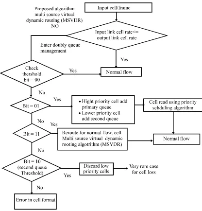
Fig. 2: Doubly finite queue management
Fig. 3: Flow diagram for doubly finite queue management
RESULTS AND DISCUSSION
In this study, we present simulation results which demonstrate the performance of the MSVDR scheme. We evaluate the performance of the scheme based on the following items:
C Fairness in the equilibrium state allocation of the bandwidth.
C Transient behavior experienced in the presence of sudden traffic changes.
[image:5.612.82.289.98.287.2]Fig. 4: Queuing model
[image:5.612.79.287.332.549.2]Fig. 5: Generic fairness configuration
Table 1: VCS parameters
PCS 150 150 150 150 150
MCR 0.15 0.15 0.15 0.15 0.15
ICR 7.5 20 0.5 0.5 0.5
MAX_air (Mbps) 2 8 1 1 1
MIN_air (Mbps) 0 0 0 0 0
MDF 4 4 5 5 5
NC 32 32 32 32 32
DTP (cell times) 128 64 128 128 128
DTT (cell times) 16 16 16 16 64
no_of_RM 1 1 1 2 4
C Maximum and mean buffer length in different network scales.
The queueing model of the simulations is illustrated in (Fig. 4). The transmitter (T) always serves the RM cells in preference to the data cells. In all simulations, we assume that all VCSs are persistently greedy i.e., all VCSs will attempt to transmit data cells at their peak cell rate. Each transmitter (T/R) will independently remove data cells from the VCS buffer and transmit them to the receiver (R). The intelligent holding will be performed by a bottleneck switch if the number of cells queued in the buffer (data cell and RM cell buffer) in the forward direction exceeds a threshold value. In all simulations, the threshold value is considered 50 cells. The VCS parameters used in the simulation are listed in (Table 1).
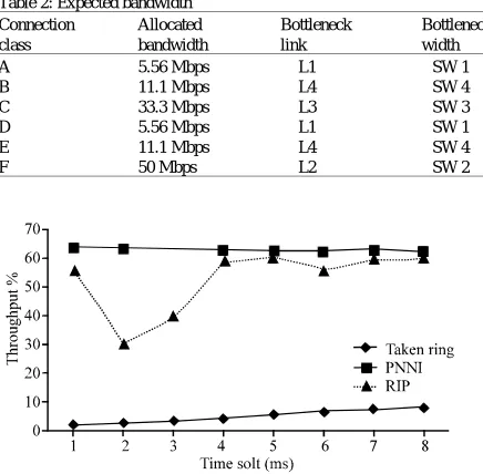
Table 2: Expected bandwidth
Connection Allocated Bottleneck Bottleneck
class bandwidth link width
A 5.56 Mbps L1 SW 1
B 11.1 Mbps L4 SW 4
C 33.3 Mbps L3 SW 3
D 5.56 Mbps L1 SW 1
E 11.1 Mbps L4 SW 4
F 50 Mbps L2 SW 2
Graph 1: Throughput comparison of PNNI, RIP and token ring protocols
consists of 5 switches with links of various capacities. We consider fairness performance in a LAN environment. The distance between VCS/VCD and its nearest switch is about 100 m and the distance between 2 switches is about 400 m.
Let us consider to connections, class B and E, which share the same bottleneck link L4. Since the VCS of class E is closer to the link and passes more congested switches than that of class B, class E will get more of the link bandwidth than class B. This is analogous to a parking lot scenario in which E is closer than B from the exit. However, in a good ATM network with separate VCs for class B and E, they will share the available bandwidth of the link fairly (in this case 100 Mbps). Thus, each connection in class B and class E should take about 1/9 of the bandwidth (or 11.1 Mbps).
Considering the above fairness objective, we can allocate the bandwidth of each link to each connection as follow.
C The VCs on the most congested link will share the link bandwidth equally and this determines the rates to be set for these VCs.
C Then apply the procedure to the other VCs with the remaining bandwidth of the network.
C Continue repeating the procedure until rates for all the VCs have been assigned.
C Using the above fair rate-setting procedure, the bandwidth assigned to individual connection classes is shown in (Table 2).
Graph 2: Delay time and queue length for queue in MSVDR
Graph 3: Queue management vs link throughput using MSVDR and DFQ
Maximum throughput: Using the doubly finite queue mechanism the ATM switches, the link utilization is very high because of at that time of congestion occur, the cell are added in the primary queue, the primary queue first threshold bit set 01 then the high priority cell added to primary queue and lower priority cell added to second queue. Whenever the primary queue second threshold bit is set to 11 then we call the MSVDR algorithm. The algorithm search the least loaded link from congested place to destination node, the maximum data transferred through this least loaded link to destination, so the maximum link utilization is done by using this algorithm and produced high throughput is shown in the Graph 1.
Minimizing queue delay time: Graph 2 describes the queuing delay time for each and every transmitting node and queue length for finite queue is minimize, the loss of the data is automatically reduced, then avoid the same cell retransmission.
DFQ management produced the maximum link throughput PQ : Primary Queue. compare than the other buffer management technique with
scheduling algorithms.
CONCLUSION
The fairness of the multiple protocol running over a simple ATM ABR network is studied through simulation under ABR RTT and ABR DFQ mechanisms, considering variable background traffic level. With our results we have shown that ABR DFQ mechanism which we conceived has improved the fairness among multiple connections with difference protocols. Although, throughput and efficiency performance level are increased in our proposal, especially when the background traffic level is high, we have resulted that enough buffer space mitigates this overhead problem. In this study, we provided only preliminary study about ABR DFQ mechanism. Much more Research is necessary to carefully analyses the performance in more complex network.
Future research will also address the possibility of achieving higher utilizations still, by including some ABR traffic. The non-RT data sources used in this research are not truly ABR sources in that the rate control scheme only applies at the UNI. The application (user process) is assumed to react to congestion by reducing its rate of transmission. A more realistic situation will require the explicit modeling of resource management cells and their transit across the entire networks.
Notations:
DFQ : Doubly Finite Queue. t (k)a : Time of arrival of a cell. TAT : Theoretical arrival time.
QPT(k) : Queue Processing Time of Arrival k cell.
I : Increment.
S (k)a : Confirming Cell Size. ALC : Available Link Capacity. QTH : Queue Threshold. CPL : Cell Priority Level.
SQ : Secondary Queue.
MSVDR : Multi Source Virtual Dynamic Routing.
REFERENCES
ATM Forum, 1999. Traffic Management Specification Version 4.1.
Andrea Bianco, 1994. Performance of the TCP Protocol over ATM Networks. ICCCN.
Macro, A., 1995. Marsan andrea Bianco, Renato L. Cigno and Maurizio Munafo. ‘TCP over ABR: Some Preliminary Simulation Results, 1st IFIP Workshop on ATM Traffic Management.
Ramakrishnan, K.K. and R. Jain, 1990. A binary feedback scheme for congestion avoidance in computer networks. ACM Transaction Computer System. Charny, A., D.D. Clark and R. Jain, 1995. Congestion
control with explicit rate indication. In: Proceedings of ICC.
Charny, A. and K.K. Ramakrishnan, 1996. Time scale analysis of explicit rate allocation in ATM networks. In: Proceedings of Infocom.
The ATM Forum Technical Committee, 1996. Traffic Management Specification. Version 4.0, af-tm-0056.000.
Lengliz, I. and F. Kamoun, 2000. A rate-based flow control method for ABR service in ATM Networks. J. Comput. Networks, 34 :129-138.
Subramani, A. and A. Krishnan, 2007. Multisource virtual dynamic routing algorithm for cell based congestion control in ATM networks. GESTS Internationla Transaction Computing Sciences Engineering, Vol. 2 No. 42.