© 2019, IRJET | Impact Factor value: 7.211 | ISO 9001:2008 Certified Journal
| Page 6082
Comparative Study of Super-Structure Stability Systems for Economic
Considerations
Atharva Ramdurgkar
1, Nikhil Naik
2, Ms. Anusha P Gowda
31,2
Undergraduate Student, Department of Civil Engineering, Reva University, Bangalore-64
3Assistant Professor, Department of Civil Engineering, Reva University, Bangalore-64
---***---Abstract -
The scope of the study includes analysis and design and comparison of waffle slab, flat slab and conventional slab system. Design of the slab systems are done for different spacing/ grid size of column to find out which grid size of the column spacing or plan area, which slab type is economical. The plan includes 36x36m in which variation of column spacing 6x6m, 9x9m, 12x12m and vertical variations are 10 story with each storey height being 3.5m for each system. Code referral basis are IS 456:2000 and IS 875, 1893:2000. Material overuse could be usually done if the sections and rebar quantity provided is in excess, that is either by over reinforcing or excess cross sectional area of elements. Hence to optimize the same, a comparative study of structural analysis for the above mentioned grid spacing is carried out (Limit State), and ultimately the best economical system is found out leading to less consumption of construction materials (10 percent wastage included).Key Words: Structural systems, Flat slab, Waffle slab,
Comparision, Costing
1. INTRODUCTION
Civil engineering has various branches among which structural engineering is a branch related to buildings whose elements are subjected to a bending moment, shear force, vertical, horizontal displacements, axial and shear forces. Analysis of such parameters can be done manually as well but since its a complex task, we rely on software such as ETABS, STAAD PRO, SAFE and many more. Among various softwares used for analysis we have used ETABS and SAFE. ETABS is used for the frame analysis for various cross sections of columns and beams and to find out the resulting shear, torsion, bending moment, deflection of the frame and slab and for the design of the same. In real life commercial construction, client with a property consults the architectural consultancy which further recommends or uses its in-house experts for the respective nature of jobs. Our scope comes under structural part, the available property area is 36x36m, hypothetically, for the purpose of this project.
2.
Literature Review:
K.N. MATE (June 2015) studied about the benefits of flat slab construction, its ease of getting constructed, placing
of formwork and workmanship. This comprehensive study helps us understand the selection of drop panel, sectional sizes, width of panel and detailing of reinforcement. His analysis was done in accordance to IS 456:2000.
D.RAMYA (October 2015) studied the differences in analysis and design of softwares such as STAAD PRO and ETABS. It was found that the reinforcement quantity provided by ETABS was 9.25% less than STAAD PRO hence leading to cheaper construction costs. She had analyzed a G+10 story building for the same.
3. METHODOLOGY
Manual calculations for selection of
sections:-Manual calculations for approximation of sections of members of all three structural systems such as calculations for beam design, column design, membrane slab design, column width drop, stiff slab and punching shear check for the systems were performed.
Modelling, Analysis and Design using ETABS AND SAFE:-
Definition of materials, frame sections, assigning load cases and combinations for the define d load patterns of live load = 3 KN/m
And super imposed load of 2.5 KN/m
Modelling of the sectional members is done and loads are assigned to the structure.
© 2019, IRJET | Impact Factor value: 7.211 | ISO 9001:2008 Certified Journal
| Page 6083
redefined. The sections are checked for rebar percentages and preferences of bar diameters are given.
Slab modelling, design and analysis is done in SAFE. Slab sections are checked for excessive deformations and failures due to excessive moments. In flat slab and waffle slab design moments along column and middle strip and along the drop are checked and accordingly required rebar area are provided.
4. Comparison:
After the modelling and analysis is done, the models are checked and comparison of intra-system for centre to centre column spacing of 6x6 m, 9x9 m and 12x12 m is done.
The best economical intra-system is nominated for inter system comparison to find most economical system, taking into consideration all three systems.
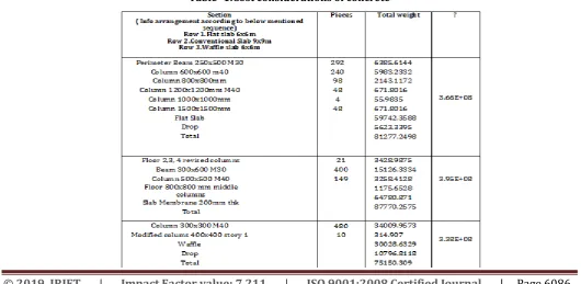
5. Calculations
:Weight of concrete of all the elements segregated according to concrete grade of M30 and M40.
Where, M40 is used for columns . M30 is used for beam and slab.
Total volume of concrete = Mass of concrete in Kg/2400 Kg/m3 .
Weights are obtained in KN to convert it into Kg, 1KN = 101.9 Kg.
Permissible deflection for Flexural members = Span/ 350 or 20 mm (whichever is less).
In our case deflection only for 6x6 m c/c column spacing goes less than 20mm i.e 17.14mm.
For Earthquake load: Calculated as per IS-1893 (part 1): 2002
Seismic Definition
Earthquake zone – III (Z=0.36) Response reduction factor – 5
Importance Factor – 1 (Very Important Building) Rock and Soil Site Factor- 2 (Medium Soil) Type of Structure- 1
Damping - 5% (0.05) Soil Type: Medium soil
Natural Time Period (Ta) - 0.075h0.75 (Ta = 0.73199 sec)
Sl.no Item
description Rate
1. CONCRETE
1.1 M30 Rs. 4,200/- PER CUM
1.2 M40 Rs. 4,800/- PER CUM
2. STEEL FE - 415 Rs. 55,000/- PER TONNE
5.1 Design calculations
(for selection of trial cross sections):
1.Design of flat slab(w/drop):
Depth= l/d = 26 x MF (ref IS456 Pg 38)
Consider pt %=4%
*Depth d= 177.51 mm.
Over all depth= 200 mm.
d= 200- 1/2 -30
D=165 mm.
W=15.75.
Load Calculations :-
Self wt. Of Slab = t x 25 =0.2 x 25 = 5.
Floor finish =2.5
Dead load = 7.5 KN/m.
Live Load = 3 KN/m.
Total Dead Load = 10.5 x 1.4 =15.75 KN/m.
Stiffness for slab:-
Longer span
For slab = Ks = 4EI/L = 4 x E x ((6000 x2003)/(6000x12)) = 2.6x10⁶.
For column = Kl = 4EI/L = 4 x E x ((400 x 4003)/(6000x12)) = 2.4380x10⁶.
Ɑc=1.066
Shorter Span
Ks = 4EI/L = same
Kc = Same
LL/DL = 3/7.5 = 0.1 <= 0.5
No need of pattern load check
Total design Moment
© 2019, IRJET | Impact Factor value: 7.211 | ISO 9001:2008 Certified Journal
| Page 6084
REBAR AREA:
-ve (depth= 162mm) (MS)
+ve(d= 162mm) (CS)
-ve(d= 162mm)
(MS)
+ve(d=1 62mm)( CS)
moment 0.75 x 0.65 x
M0
= 231.64
0.35 x 0.60 x M0 = 99.78
0.65 x M0 = 77.217
0.35 x M0 = 66.528
Pt(%) 0.556 0.57 0.433 0.37
Area(m
m) 2780 1846.8 1402.92 1199.26
CHECK FOR 2 WAY SHEAR:
d/2 = 250/2 = 125
B0 = 550 x 4 = 2200mm
Vu = (62 - 0.552 )x 19.5.5
Vu = 696.10 KN
Ʈv = Vu/b0 d = 1.2656 N/mm
FLAT SLAB DESIGN: (6 x 6 m )
Drop = 250mm thick
Falt slab = 200 mm thick
Column = 300 x 300
Loads Calculations: DL = 0.2 x 25 = 5 kN/m
LL = 3kN/M
SDL = 2.5 kN/M
TDL = 7.5 kN/M
Depth of slab = 200 mm = D
d = 162 mm
Stiffness( LS = SS)
Ks = 4EI/L
KS = (4 x E x 6000 x 2003 )/ 6000 x 12 = 9 x 10⁶
Kc = 4EI/L =( 4 x E x 400 x 4003 )/ 12 x 6000
Kc = 4EI/L = 1.42 x 10⁶
αc = 0.157
LL/DC = 3/7.5 = 0.4 <= 0.5
Therefore there is no need for pattern load check.
Ʈc’ = ks x Ʈc
Ks = o.5 + 300/300
Ks = 1.5 > 1.0
If ks > 1
Consider ks = 1
Ʈc =0.25√fck = 0.25√30 = 7.5 N/mm2
Ʈv < Ʈc
No shear reinforcement required.
BEAM DESIGN OF 9x9m CONVENTIONAL SLAB:
Mu = Mulim + M2
M2 = Mu - Mulim
Mulim = 0.36fck x Xumax x b x (d - 0.42Xu) ………. tension steel
M2 = 0.87fy x Ast2 x (d - d1) ……….. tension steel
M2 = (fsc - fcc) x Asc x (d - d’) ……… Compaction steel
Xu/d = 0.48
Xumax = 0.48 x d
Xumax = 0.48 x 600 = 288 mm
1)Mu = 196 KN
Mulim = 0.36fck x Xumax x b x (d - 0.42Xu)
= 0.36 x 30 x 288 x 300 x (600 - 0.42 x 288)
Mulim = 447 KNm
Mu = Mulim + M2
M2 = 447 - 196
= 251 KNm
M2 = 0.87fy x Ast2 x (d - d1)
251 = 0.87 x 415 x Ast2 x (600 - 30)
© 2019, IRJET | Impact Factor value: 7.211 | ISO 9001:2008 Certified Journal
| Page 6085
M2 = (fsc - fcc) x Asc x (d - d1)
251 = (355 - 13.5) x Asc x (600 - 30)
Asc = 1289.46 mm2
C =T
0.36 fck Xub =0.87 fyAst
Ast1= (0.36 x 30 x 288 x300)/(0.87 x 415)
Ast1 = 2584.46. mm2
Tension steel = Ast1+ Ast2 = 2584.46 +1219.639
Tension stell = 3804.10 mm2
Compression steel =1289.46 mm2
Shear Reinforcement :-
W = Self wt. Of slab acting on beam =45 +45. (two tributaries)
LL = 3 KN/m
SDL =2.5 KN/m
Self wt. Of beam =4.5 KN/m
Total wt =102.5 KN/m x 1.5 =153.75 KN/m
Vu = wl/2 =(153.75 x 6)/2= 461.25 KN.
Critical section occurs at ‘d’ from support:-
* 461.25 /3 = Vuc/(3 - 0.6)
Vuc =369 KN
Pt % =( Ast x 100)/bd =2011% for M30,
Ast 100/ bdτc
By interpolation,
2.0 0.84
2.110.8576
2.25 0.88
sDesign Shear Strength = Ʈc =0.8576 N/mm2
Design Shear force = Vus =Vuc -Ʈc bd
=369 -( 0.85 x300 x600x103 )
Vus = 216 KN.
Vu =0.87fy Asv sinα
Vus = 0.87 x415 x628.31 x sin 45°
Vus =329 KN.
Shear force resisted by bent up bars = 329/ 2
Shear force resisted by stirrups = 329 - 164 = 164 KN.
*Shear force resisted by stirrups=
Vus =σ sv x (Asv/Sv)x d
=0.87 fy Asv d/Sv
164 x 103 = 0.87 x 415 x 2 x π/4 x 82 x 600 /Sv
Sv= 132 mm.
Minimum spacing =126.515
1)0.7 d= 450
2)300
3)Sv =132mm (considered)
Provide 132 mm 2 legged c/c 18mm ϕ bars.
Slab design (membrane):-
ly/ lx = 6/6 = 1<2
*Two way slab
1)Depth of slab = l/d =26
d= l/(26 x MF)
*d = 9000/ 26 x 1.5 =153.85/230
Taken 200mm thick
l = 25 mm
d =200 + 25 =225 mm
2)Eff. Span
lff= lx + depth =9200 mm
3)Load calculation
DL=0.225 x 25
DL = 5.625 KN / m2
LL = 3 KN/m2
© 2019, IRJET | Impact Factor value: 7.211 | ISO 9001:2008 Certified Journal
| Page 6086
Total load =11.125 KN/m x 1.5 =16.6875 KN/n
Mx = ɑxwlx2
My = ɑywlx2
For ly /lx, ɑx = 0.062
ɑy = 0.062
Mx = 0.062 x 16.7 x 90002 = 83.86 KNm
My = 0.062 x 16.7 x 90002 = 83.86 KNm
Check for depth :-
Md = 83.86 KNm
Md = 0.36fck x Xumax x b x (d - 0.42Xumax)
83.86 x 106 = 0.36 x 30 x 0.48d x 1000 x (d - 0.42 x 0.48 x d)
= 5104d - 1045.0944d
= 4138.9d
d = 202.613 < 225mm
Calculation of steel :-
Astx - 0.5fck/fy [ 1 - √(1 - 4.6)/(fck x b x d2) ] x b x d
Asty = 1274.216 mm2
Asty = 1274.216 mm2
Spacing = (Area of 1 bar x 1000)/ Ast req.
= [(π/4) x 162 x 1000]/1274.216
= 157 ≈ 150 mm
Provide 16mm dia bars @ 150mm c/c
COLUMN DESIGN:
Pu = 0.45 fck Ac + 0.67 fy Asc
Axial load Pu = 13427 KN
Axial load includes self weight of all the corner beams and slabs, Live load pof 3 KN and SDL of 2.5KN,on each floor.
Ag = Asc + Ac
Assume pt % = 5%
Therefore Asc = 0.05 Ac
13427x103= 0.45 x 40 x Ac + 0.67 x 415 x 0.05 x Ac
Therefore Ac= 421220.814 mm2
Size of a square column comes up to 650mm,
Since we are adopting minimum reinforcement and increasing the colum,n area for compensation, size of column to be adopted is 900x900mm.
Hence, Asc = 0.05 Ac
= 0.05 x 421220.814
[image:5.595.33.564.528.787.2]Asc = 21229.52903 mm2
© 2019, IRJET | Impact Factor value: 7.211 | ISO 9001:2008 Certified Journal
| Page 6087
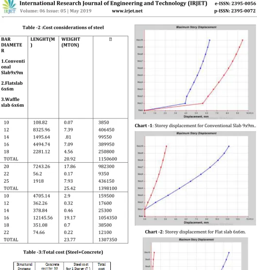
Table -2 :Cost considerations of steel
BAR DIAMETE R
1.Conventi onal Slab9x9m
2.Flatslab 6x6m
3.Waffle slab 6x6m
LENGHT(M
) WEIGHT (MTON) ₹
10 12 14 16 18 TOTAL
108.82 8325.96 1495.64 4494.74 2281.12
0.07 7.39 .81 7.09 4.56 20.92
3850 406450 99550 389950 250800 1150600 20
22 25 TOTAL
7243.26 56.2 1918
17.86 0.17 7.93 25.42
982300 9350 436150 1398100 10
12 14 16 18 22 TOTAL
4705.14 362.26 378.84 12145.56 351.08 74.66
2.9 0.32 0.46 19.17 0.7 0.22 23.77
[image:6.595.322.542.530.732.2]159500 17600 25300 1054350 38500 12100 1307350
Table -3:Total cost (Steel+Concrete)
The one marked in grey is the cheapest.
Chart -1: Storey displacement for Conventional Slab 9x9m..
Chart -2: Storey displacement for Flat slab 6x6m.
© 2019, IRJET | Impact Factor value: 7.211 | ISO 9001:2008 Certified Journal
| Page 6088
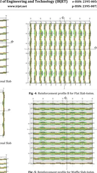
Fig -1: Reinforcement profile A for Conventional Slab 9x9m.
Fig -2: Reinforcement profile B for Conventional Slab 9x9m.
Fig -3: Reinforcement profile A for Flat Slab 6x6m.
Fig -4: Reinforcement profile B for Flat Slab 6x6m.
Fig -5: Reinforcement profile for Waffle Slab 6x6m.
[image:7.595.52.422.50.608.2] [image:7.595.237.555.51.615.2]© 2019, IRJET | Impact Factor value: 7.211 | ISO 9001:2008 Certified Journal
| Page 6089
6. CONCLUSIONS AND INFERENCES:
Waffle slab method consumes the least amount of concrete since most of the concrete below the neutral axis is removed as it is found that concrete above the neutral axis takes considerable amount of compressive stress.
The Waffle part which contains rebars act as equidistantly placed beams in a ribbed manner and the load bearing capacity of the slab increases prominently with the stiffness increasing over the entire span of slab.
Cross sectional dimensions of the frame elements increase as the c/c spacing increases.
Deflection is considerably reduced as the cross section of vertical frame elements are increased rather than horizontal.
Beam and Slab system is more prone to deflection rather than the other two as the slab element comprises of membrane as opposed to shell thin in flat slab and waffle slab.
The concrete pricing for 10 storey and steel pricing for 1 storey are mentioned below and an inference can be made that waffle slab 6 x 6 m comes out as the most economical structural system for a total span of 36 x 36 m plot.
REFERENCES
• Plain & Reinforced Concrete Code of Practice” Fourth Revision IS: 456:2000.
• IS 875:Part 2, 3
• IS1893-2002: Indian Standard Code of Practice for Criteria for Earthquake Resistance Design of Structures. RCC design by Pillai and Menon. • K.N. Mate, Volume 4 Issue 6, June 2015 Study of
Flat Slab, International journal of science and research (IJSR), pp.1106-1110.
• Mohana H.S, Volume 02 Issue 03, June-2015 Comparative Study of Flat Slab and Conventional Slab Structure Using ETABS for Different Earthquake Zones of India, International Research Journal Of Engineering and Technology (IRJET).pp.1931 – 1936.
• RCC design handbook by Pillai and Menon. • Public Works, Ports and Inland Water transport
department Bengaluru Circle, Bengaluru 2018-2019 Schedule of Rates.
BIOGRAPHIES
Atharva Ramdurgkar,
Undergraduate student at Reva Univeristy, Bangalore-64, Karnataka.
.
Nikhi Naik, Undergraduate student at Reva University, Bangalore- 64, Karnataka.