© 2019, IRJET | Impact Factor value: 7.211 | ISO 9001:2008 Certified Journal
| Page 8073
EVALUATION OF ERNiCrFe-7A FILLER WIRE FOR DISSIMILAR WELDING OF
SS304H & T91 MATERIAL USING HOT-WIRE TIG WELDING PROCESS
Shekhar Chandra Pratap
1, T Senthilkumar
2, Vishal Singh
3, A Santhakumari
41
Student, M.E., Anna University, Trichy, India
2Dean, Anna University, Trichy, India
3
Senior Engineer, Welding Research Institute, BHEL, Trichy, India
4Additional General Manager, Welding Research Institute, BHEL, Trichy, India
---***---
Abstract: To study investigates the weldability, metallurgical and mechanical properties of the dissimilar joints of SS 304H and T91 material using Inconel filler wire 52 (ERNiCrFe-7A) for Advanced Super Critical Boiler application. The welding process used for this study is Hot-Wire Gas Tungsten Arc Welding (HW-GTAW) process. Various samples have been prepared using the standard edge preparation style. Welding has been conducted on various specimen by varying the process parameters to finalized welding parameters which are used to carry out welding on final specimen. The samples were evaluated by non-destructive testing, optical microscopy, tensile testing, bend testing and hardness measurements.
Microstructural characterization was carried out to identify various zones on eitherside of the fusion boundaries. Micro-hardness profiling indicated increase in hardness at the HAZ towards T91 fusion boundary. Mechanical properties evaluation was carried out and data obtained was compared with those of base metals. The tensile strength of cross weld specimens at high temperatures were observed to be closer to that of T91, but significantly more than that of SS 304H.
Keywords: SS304H, T91, Hot-wire Gas Tungsten Arc Welding
1. Introduction
High efficiency Super-Critical power plants are extensively researched upon due to the increased environmental protection measures in recent times. The key for achieving higher efficiency is to either increase the inlet temperature of the turbine or to decrease the ambient temperature which is impossible. Hence, there has been tremendous need for high temperature material development. Many super-alloys (Inconel 617, Inconel 740, Hayness 263, Hayness 282, etc.) and new generation steels (Super 304H, T92, etc.) are developed paving the way for development of Super Critical Boiler Technology.
For high efficiency Super-Critical technology, high temperature materials particularly advanced austenitic steels
and super-alloys are of prime interest. High efficiency boilers consist of components which are fabricated using various materials and this creates a necessity to weld various combinations of material which may be similar or dissimilar materials.
SS 304H, austenitic stainless steel was proposed to be used at moderately high temperature sections of the boilers and T91 materials is proposed to be used for panels and headers. Therefore, development of dissimilar joining technology involving T91 and SS 304H was essential. Hence, the present investigation was carried out to develop welding procedure, optimize welding parameters, characterize the weld joint and infer about effect of various zones of weldment on mechanical properties.
The present work is organized as follows: Information about the materials used, successful development of the welding procedure employed for obtaining defect-free dissimilar welds, sample preparation, characterization and testing procedures employed are indicated in Section 2. Results and discussion related to extensive microstructural characterization studies that were carried out after welding, ambient and high temperature mechanical properties of the weldments obtained are explained in Section 3. Conclusions drawn from the present work are indicated in Section4.
2. Experimental details
2.1 Material
© 2019, IRJET | Impact Factor value: 7.211 | ISO 9001:2008 Certified Journal
| Page 8074
Table 1: Chemical composition of materials
Eleme
nt T91 SS304H ERNiCrFe-7A
C 0.07 – 0.14 0.04-0.1 0.04 max Si 0.2 – 0.5 <=0.75 0.50 max Mn 0.3 – 0.6 <2 1.0 max
P 0.02 max <=0.045 0.02 max
S 0.02 max <=0.03 0.015 max
Al 0.015 max 1.10 max
Cr 8 – 9.5 18-20 28.0-31.5
Mo 0.85 – 1.05 0.50 max
Ni 0.04 max 8-10.5 Balance
V 0.18 – 0.25
N 0.03 – 0.07
Nb 0.08 0.10 max
Cu 0.2 max 0.30 max
Ti 0.002 1.0 max
Fe Balance Balance 7.0-11.0
2.2 Welding procedure
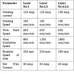
The base metal (i.e. T91 tube and SS304H tube) is cut into the length of 300 mm each. Cutting, machining and edge preparation of SS304H and T91 base metal were carried out as per ASME guidelines. Schematic of the edge preparation arrangement utilized for horizontal position welding is indicated in Fig. 1. For welding of the specimen the Hot-wire Gas Tungsten Arc welding process has been used. The schematic of the Hot –wire Gas Tungsten process is shown in the Fig. 2. Argon gas is used for back purging of root pass and shielding gas for subsequent passes. All the passes required for obtaining a sound dissimilar weld joint were carried out manually by the same trained welder in a single welding session. Inter-pass oxides and the fusion zone were cleaned by wire brush in between passes. Initial weld trials produced joints which were subjected to Radiographic Testing (RT) for revealing presence of defects. Radiographs were recorded with 2/2T sensitivity on a very fine grain, high contrast film located at a focal distance of 500 mm. The initially observed defects such as porosity, lack of fusion, weld depression, etc. was later eliminated by optimizing welding parameters. The process parameters were established after conducting iterative studies and are shown in Table 2. It took a total of 6 passes to successfully complete the welding. Preheating is
[image:2.612.61.277.93.410.2]carried out at 150 - 200ºC during welding to drive off moisture.
Table 2: Welding Parameters
Parameter Layer
No.1 Layer No.2,3 Layer No.4,5,6
Welding
current 120 Amp 125 Amp 130 Amp
Welding
Speed 100 mm/min 100 mm/min 100 mm/min Wire Feed
Speed 650 mm/min 650 mm/min 650 mm/min
Wire Oscillation Speed
800
mm/min 1200 mm/min 1800 mm/min
Rotation Speed of tube
250 rpm 250 rpm 250 rpm
Hot Wire
[image:2.612.323.569.116.657.2]Current 30 Amp 30 Amp 40 Amp
Fig. 1. Edge preparation style
Fig. 2. Schematic diagram of HW-GTAW process.
37.5±2.5º
31±1.1º 12
T
STYLE - H
R1
d1
GTA Power source
Wire heating power source
Tungsten Ceramic
guide TIG
torch
Ia Contact Iw
tube
Wire feeder
[image:2.612.317.572.126.381.2]© 2019, IRJET | Impact Factor value: 7.211 | ISO 9001:2008 Certified Journal
| Page 8075
2.3 Mechanical properties evaluation
Hardness profiling on cross-weld specimens with an indent spacing of 1000 µm and 0.3 kg load with 25.799 s dwell time was carried out across the various zones of base metals and weld metal.
Tensile testing was carried out at room temperature and 650°C by employing an extension rate of 0.3 mm/min on 1000 kN Universal Testing Machine equipped with a high temperature furnace. Cross-weld samples containing all zones of the weld were prepared from welds in transverse direction as per the ASTM E8-M.
2.4 Metallography and microstructural examination
Characterization studies were carried out on samples which were cut from base metal plates and transverse sections of the weldments after discarding about 15 mm from either end of the weld plate. These samples were mechanically ground in series from 120 to 1200 silica emery grit and were sequentially polished using 9 μm, 6 μm, 3 μm, 1 μm, 0.25 μm polycrystalline diamond suspensions. Subsequently, final polishing was carried out with 0.02 μm colloidal silica suspension in order to obtain extremely good surface finish. These samples were later etched chemically using aqua-regia (mixture containing 1:3 volume ratio of HNO3 to HCl). The etched samples were observed for features
are pertaining to morphology of grains and precipitates under metallurgical microscope using both bright field and dark field modes.
3. Result & Discussion 3.1 Bend Test
Bend tests are generally used in the weld qualification process for new fabrication. The Guided bend tests are used to evaluate the ductility and soundness of welded joint and to detect incomplete fusion, cracking, delaminating effect of bead configuration, and macro defects of welded joints. The quality of welds can be evaluated as a function of ductility to resist cracking during bending. The tests were conducted at room temperature. The bend tests are made in two directions on each sample; transverse face bend test and transverse root bend test. All the samples were bent to an angle of 180 °. The result of bend test on weldment is as follows. Fig. 3.
[image:3.612.346.554.67.200.2]No defect was observed in the transverse root bend test but one of the specimens in transverse face bend test was observed to have an opening of 1.93 mm. As per ASME Section IX QW-163 any open discontinuity in the weld or heat affected zone should not exceed 3 mm. Hence, the weld joint satisfies the criteria of bend test.
Fig. 3. Bend test specimen
Table 3: Result of bend test
Test Specimen Observation Result
Root bend test
Specimen
1 No observed crack is Acceptable Specimen
2 No observed crack is Acceptable Face
bend test
Specimen
1 No observed crack is Acceptable Specimen
2 1.93 mm opening is observed Acceptable
3.2 Tensile Test
Tensile test is conducted at room temperature and 650 ºC. It was observed at room temperature the average value of UTS of weld joint is 664 MPa. which is higher than the minimum required tensile strength for ERNiCrFe-7A electrode and base metals (i.e. 590 MPa for electrode, 585 MPa for T91 & 515 MPa for SS304H) as per ASME Section II Part C.
Fig. 4. Hot-Tensile test specimens
Specimen Temp. (οC)
UTS (MPa)
1 25 699 Weld metal
2 25 691 Weld metal
3 25 664 Weld metal
[image:3.612.337.561.484.613.2]© 2019, IRJET | Impact Factor value: 7.211 | ISO 9001:2008 Certified Journal
| Page 8076
5 650 330 HAZ of T91
6 650 307 HAZ of T91
7 650 322 HAZ of T91
8 650 334 HAZ of T91
In case of Hot-Tensile test all the specimens are raised upto 650ºC, then load is applied gradually till facture occurs. The average UTS value obtained at 650ºC is 323 MPa which is higher than the minimum strength required at 650ºC (280 MPa).
3.3 Micro-hardness Test
The hardness across the weld cross section was measured using a Vickers Micro-hardness testing machine as per the
ASME Sect. IX, and the results are presented in the below Fig.
18. Hardness is measured with an applied load of 300 gf for a dwell time of 25.6 sec. at a distance of 1mm. The micro-hardness measurements focused on the 3 regions: 1) T91 to Weld metal, 2) Vertically along the weld metal & 3) Weld metal to SS304H.
Fig. 5. Variation of hardness across the weld metal
According to the variation in micro-hardness across the joint, the mechanical properties will also vary. The micro-hardness profile of the weldment, is shown in Fig. 5, indicates the increase in the value of micro-hardness while moving from weld metal to T91 BM through HAZ. Similarly, some micro-hardness increase is being observed while moving from weld metal towards SS304H base metal through the HAZ of SS304H. The average micro-hardness of the HAZ of T91 is 451Hv, whereas for weld metal and HAZ of SS304H, the value measured to be 210Hv and 227Hv respectively. The interface of weld metal with HAZ of T91 has an unmixed layer, where an increase in micro-hardness has observed followed by microstructures of CGHAZ and FGHAZ of T91, where further increase in micro-hardness is noticed due to martensitic structures. The presence of phases of martensite and (Cr,Fe)7C3 along with the needle shaped martensitic
morphology of this region.
In the similar manner the micro-hardness value increases on the HAZ of SS304H, is due to the presence of some hard layer of carbides in the microstructures of HAZ of SS304H. Henceforth the precipitations of hard phases on the both sides of the weld metal are believed to increase the micro-hardness.
3.4 Macrostructure of weldment
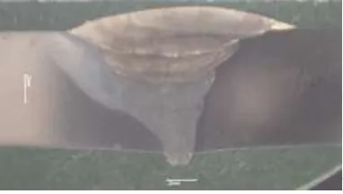
The cross-section macrographs of the dissimilar weldment of SS304H and T91 employing HW-GTAW welding method and filler wire are represented in Fig. 6. Macro-structure examination ensured that the welding techniques (i.e. HT-GTAW) and filler metal (i.e. ERNiCrFe-7A) employed in this study exhibited proper fusion with the base metals. Further NDT analysis has shown clearly that the weldment is free from under-cuts, porosities, inclusions, etc.
[image:4.612.354.545.277.385.2]l
Fig. 6. Macro-etched weld joint
[image:4.612.56.295.330.463.2]3.5 Microstructure examination
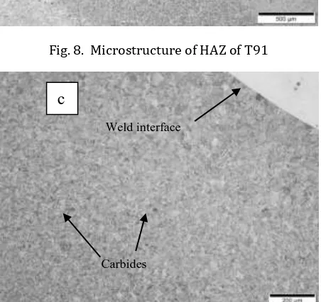
Fig.7 shows the different structural zones of the T91 HAZ. The HAZ consists of structural zones typical to low-alloy steel: grain coarsening, grain refining, and partial grain refining zone. The microstructure of the base metal is bainitic.
© 2019, IRJET | Impact Factor value: 7.211 | ISO 9001:2008 Certified Journal
| Page 8077
in the presence of some delta ferrite indicated in Figs. 10. Delta ferrite is a chromium rich phase of Fe-Cr alloys and may have formed due to depletion of Cr from the alloy matrix. The presence of delta ferrite in addition to martensite structure of HAZ of T91 can facilitate the depletion of Cr through precipitation and ultimately affect the oxidation resistance of the region. An unmixed layer is being observed at the interface of weld metal and HAZ of T91 as seen in Fig. 9. The unmixed layer is being made by the melting of T91 base metal and re-solidified without going to dilute with the weld metal.
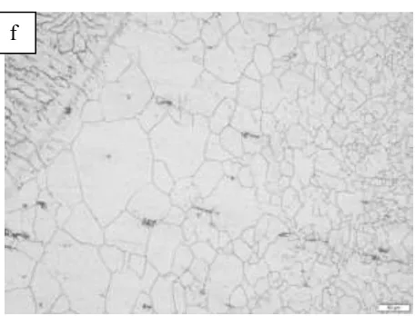
The interface of the weld metal with the HAZ of T91 experience epitaxial growth towards weld metal, whereas the middle of the weld metal is fully austenitic shown in Fig. 11. The vermicular shape of the microstructure is being observed. As ERNiCrFe-7A weld metal contains a higher percentage of nickel, it does not indicate any solid-state transformation during cooling and remains austenitic. The microstructure toward the HAZ of the 304H shows re-crystallization of the austenitic structure as shown in Fig. 12.
The microstructure of SS304H base metal as shown in consists of equi-axed grains on austenitic field. On the SS304H steel side of the weldment, no such martensitic-austenitic transition occurs. The HAZ of the SS304H develops austenite structure with re-crystallization of carbide precipitates shown in Fig. 12. Carbides of Cr23C6, Cr7C3 and
[image:5.612.333.560.68.241.2](Cr, Fe)7C3 along with the phases of austenite are seen.
[image:5.612.333.559.219.432.2]Fig. 7. Microstructure of Base Metal T91
[image:5.612.56.275.415.601.2]Fig. 8. Microstructure of HAZ of T91
Fig. 9. Weld interface of T91
Fig. 10. CGHAZ of T91
CGHAZ of T91
FGHAZ of T91
a
Base metal of T91
Carbides
c
Weld interface
d
b
[image:5.612.333.556.486.662.2]© 2019, IRJET | Impact Factor value: 7.211 | ISO 9001:2008 Certified Journal
| Page 8078
Fig. 11. Microstructure of weld metal
Fig. 12. Microstructure of HAZ of SS304H
4. Conclusions
Based on the present study, the following can be concluded:
4.1 Hot wire GTAW welding process can be used for
fabrication of defect-free dissimilar welds of SS304H and T91 metals using ERNiCrFe-7A filler material.
4.2 Micro-hardness profiling indicated that HAZ of alloy
T91 has higher hardness due to needle shaped martensite at HAZ.
4.3 The observed presence of martensite phase along
with carbides in the HAZ of T91 side is another probable reason for the higher micro-hardness.
4.4 Tensile strength of transverse tensile specimens was
closer to that of T91 base metal and was significantly higher than SS304H, thus, qualifying the welds applicability for High efficiency boiler components.
References
[1] Kourdani, Ahmad & Derakhshandeh Haghighi, Reza., Evaluating the Properties of Dissimilar Metal Welding Between Inconel 625 and 316L Stainless Steel by Applying Different Welding Methods and Consumables. Metallurgical and Materials Transactions – 2018 A. 49. 10.1007/s11661-018-4469-7.
[2] R. Ravibharath, A.H.V. Pavan, K.S.N. Vikrant, Kulvir Singh, Development and evaluation of SUS 304H — IN 617 welds for advanced ultra-supercritical boiler applications, Materials Science & Engineering, June 2015.
[3] K. Devendranath Ramkumar, Siddharth D. Patel, S. Sri Praveen, Dip Joy Choudhury, P. Prabaharan, N.Arivazhagan, M. Anthony Xavior, Influence of filler metals and welding techniques on the structure– property relationships of Inconel 718 and AISI 316L dissimilar weldments.Materials and Design · October 2014.
[4] G. Magudeeswaran, Sreehari R. Nair, L. Sundar and N. Harikannan, Optimization of process parameters of the activated tungsten inert gas welding for aspect ratio of UNS S32205 duplex stainless steel welds, Defence Technology Volume 10, Issue 3, September 2014, Pages 251-260.
[5] P. Mithilesh, D. Varun, Ajay Reddy Gopi Reddy, K. Devendranath Ramkumar*, N. Arivazhagan, S. Narayanan, Investigations on Dissimilar Weldments of Inconel 625 and AISI 304, 7th International Conference on Materials for Advanced Technologies 2013.
[6] N. Arunkumar, P.Duraisamy and S.Veeramanikandan, Evaluation of Mechanical Properties of Dissimilar Metal Tube Welded Joints Using Inert Gas Welding, International Journal of Engineering Research and Applications (IJERA) Vol. 2, Issue 5, September- October 2012, pp.1709-1717.
[image:6.612.53.281.263.437.2]