warwick.ac.uk/lib-publications
Manuscript version: Author’s Accepted Manuscript
The version presented in WRAP is the author’s accepted manuscript and may differ from the
published version or Version of Record.
Persistent WRAP URL:
http://wrap.warwick.ac.uk/112521
How to cite:
Please refer to published version for the most recent bibliographic citation information.
If a published version is known of, the repository item page linked to above, will contain
details on accessing it.
Copyright and reuse:
The Warwick Research Archive Portal (WRAP) makes this work by researchers of the
University of Warwick available open access under the following conditions.
Copyright © and all moral rights to the version of the paper presented here belong to the
individual author(s) and/or other copyright owners. To the extent reasonable and
practicable the material made available in WRAP has been checked for eligibility before
being made available.
Copies of full items can be used for personal research or study, educational, or not-for-profit
purposes without prior permission or charge. Provided that the authors, title and full
bibliographic details are credited, a hyperlink and/or URL is given for the original metadata
page and the content is not changed in any way.
Publisher’s statement:
Please refer to the repository item page, publisher’s statement section, for further
information.
Robust Design for Massive CSI Acquisition in
Analog Function Computation Networks
Fan Ang, Li Chen, Nan Zhao,
Senior Member, IEEE,
Yunfei Chen,
Senior Member, IEEE,
F. Richard Yu,
Fellow, IEEE
Abstract—Analog function computation utilizes the superpo-sition property of multi-access channel (MAC) to compute the target function in an efficient way. However, its corresponding transceiver requires globalchannel state information(CSI) of the network, which incurs large latency. To tackle this challenge, a novel scheme called over-the-air signaling procedure is proposed by exploiting a defined effective CSI in this paper. We first derive the training complexity of the proposed scheme and compare it with the conventional design. It is shown that the training complexity of the proposed scheme can be greatly reduced for massive CSI acquisition by avoiding collecting individual CSI. To account for the difference of the desired CSI, a corresponding robust model is further discussed. Through modeling the channel uncertainties under the expectation-based model and the worst-case model, we formulate the transceiver optimization for both the conventional scheme and the over-the-air signaling procedure. The computational time complexity is derived as a polynomial expression, and it can be significantly reduced for the over-the-air signaling procedure due to its independence of the number of nodes. Finally, the mean-square error (MSE) improvement and complexity reduction of the proposed design are demonstrated via simulation.
Index Terms—Analog function computation, expectation-based model, transceiver design, worst-case model.
I. INTRODUCTION
F
UTURE wireless applications require higher rate, low-er latency and reliable connections with numlow-erous de-vices [1]. This makes the traditional orthogonal multi-access schemes less feasible as the excessive latency and low ef-ficiency in spectrum utilization. A seminal scheme, analog function computation, was proposed to solve this challenge. It is intelligent to exploit the signal-superposition property ofmulti-access channel(MAC) to compute the desired functions
of distributed sensing data from nodes in [2], [3].
This work has been supported by National Natural Science Foundation of China (Grant No. 61601432), and the Fundamental Research Funds for the Central Universities. This work has been supported in part by the National Natural Science Foundation of China under Grant 61871065, and in part by the open research fund of National Mobile Communications Research Laboratory, Southeast University (No. 2018D03). (Corresponding author: Li Chen)
F. Ang and L. Chen are with Department of Electronic Engineering and Information Science, University of Science and Technology of China.(e-mail: [email protected], [email protected]).
N. Zhao is with the School of Info. and Commun. Eng., Dalian University of Technology, Dalian 116024 China, and also with National Mobile Commu-nications Research Laboratory, Southeast University, Nanjing 210096, China (email: [email protected]).
Y. Chen is with the School of Engineering, University of Warwick, Coventry CV4 7AL, U.K. (e-mail: [email protected]).
F.R. Yu is with the Department of Systems and Computer Engi-neering, Carleton University, Ottawa, ON, K1S 5B6, Canada (email: [email protected]).
The idea of analog function computation can be tracked back to the information theory analysis in the pioneering work [3]. A novel structure known as compute-and-forward was provided to recover integer coefficient linear combinations, which could obtain higher computation rate by improving communication rate in [4], [5]. Afterwards, a computation scheme was studied to achieve higher computation rate by ex-ploiting the interference property of the Gaussian MAC in [6], [7]. It was based on two categories of nomographic functions proposed in [8], including linear and non-linear functions. To reduce the time and energy complexity in practical scenarios, a novel subfunction allocation was proposed to handle the frequency selective fading and vanishing computation rate issue through the division, allocation and reconstruction of the functions in [9].
Compared with the digital function computation in the aforementioned works, analog function computation can achieve lower complexity and higher energy efficiency for future wireless networks. It is only interested in the desired function values rather than individual messages of all users. The seminal work proposed the analog function computation scheme aiming at compute a variety of functions that used a simple data pre-processing and post-processing strategy in [10]. The feasibility of the analog function computation was proved by the implementation on self-developed software defined radio devices in [11]. Moreover, various applications of analog function computation have been developed for future network scenarios [12], [13]. However, several practical issues of the implementation for analog function computation should be further discussed.
The synchronization required for all nodes is still an open problem in the analog function computation networks. To the best of our knowledge, some existed methods were proposed to solve this problem. The simple robust analog joint source-channel computation was developed in [10], which trans-formed synchronization error as random noise to solve the synchronization problem. The design transforms the function computation to power detection while synchronization error appears as random noise. Subsequently, another novel way calledAirShare was studied to utilize broadcasted reference-clock signal to complete the transmission in [14], and the implementation in a network of software radios was provided.
One practical issue originates from the fading property of practical MAC, which motivates the adaptive transceiver de-sign to compensate the non-uniform fading of active nodes. A
c
⃝2015 IEEE. Personal use of this material is permitted.
uniform-forcing transceiver design was proposed to normalize the channel fading for single function computation in [15]. To compute multiple functions, related work discussed the beam-forming and channel feedback design to minimize sum
mean-square error (MSE) via spatial diversity in [16]. In parallel
with the above research, the combination of transmitter design with zero-forcing beamforming was introduced to cancel the intra-node interference of multiple functions, and they studied the uniform-forcing power control to compensate the non-uniform fading in [17].
It is worth mentioning that the above research was based on an ideal model with perfect channel state information (CSI). Practical transceivers have to operate with uncertain CSI, which inspires researchers to adopt the robust design for conventional networks in [18]–[20]. An intuitive robust precoding technique was developed to eliminate the need for postprocessing at the fusion center for wireless sensor networks in [21]. In analog function computation networks, they discussed the robust transceiver optimization for parallel analog functions computation with MAC in [22].
To the best of our knowledge, the existing methods of the transceiver design for analog function computation are based on the global CSI, which incurs extremely high training com-plexity for large-scale nodes, and makes the analog function computation lose its prime superiority of avoiding individual data aggregation. Moreover, building on the individual CSI acquisition scheme, the known robust designs are found to have high computational time complexity in [20]. This makes the efficient training process of the transceiver design an open problem.
Motivated by this observation, we propose the over-the-air signaling procedure to reduce the training complexity for massive CSI acquisition. Furthermore, since the known conventional robust designs are inapplicable for the defined effective CSI acquisition, the robust designs of the proposed solution are introduced using the expectation-based model and the worst-case model. The former is based on the statistical properties of CSI uncertainty [23], and the latter represents the fixed CSI uncertainty sets [24]. The robust designs for both models are not jointly convex for the transmitter and the receiver. Thus, we adopt an iterative algorithm to find the efficient optimal solutions. The main contributions of this work are summarized as follows.
. Over-the-air signaling procedure: A novel signaling procedure is proposed to obtain the defined effective CSI exploiting the superposition property and the chan-nel reciprocity of MAC. The receiver only requires the defined effective CSI instead of the global CSI to achieve transceiver optimization. The proposed solution is supe-rior to the conventional scheme in terms of both training complexity and MSE performance.
. Robust design with imperfect CSI: The robust design is compared between the conventional scheme and the proposed solution. Since the conventional design is in-feasible due to the difference of the desired CSI, an iterative algorithm is proposed to obtain the closed form of optimal transceiver under the expectation-based model. Furthermore, we convert the non-convex optimization
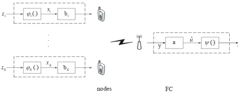
nodes FC
1
b
1
x
1( )
j ×
1
s
y a uˆ y ×( ) fˆ bK
K
x
( )
K
j ×
K
s
[image:3.612.316.560.64.162.2]. . .
Fig. 1. The analog computation network.
into semidefinite programming (SDP) via S-procedure
under the worst-case model [25], [26].
. Computational time complexity of the design: The computational time complexity is derived for both the conventional design and the over-the-air signaling proce-dure. It is found that the computational time complexity of proposed solution is only related to the number of receive antennas, which proves that the proposed solution outperforms the conventional design on the computational time complexity for massive CSI acquisition.
The remainder of the paper is organized as follows. Section II introduces the system model of analog function computa-tion. Section III presents the optimal objective of training com-plexity and robust design. The over-the-air signaling procedure and the comparison between the conventional scheme and the proposed one are presented in Section IV. Section V shows the transceiver design with imperfect CSI, and the analysis of the computational time complexity. Simulation results are provided in Section VI.
Throughout the paper, we use boldface lowercase to refer to vectors and boldface uppercase to refer to matrices respec-tively. The real numbers are denoted as R. Let A−1 denote the inverse of a matrix A. Let ∥ · ∥ denote the 2-norm of a vector or matrix, and let (·)T denote the transpose of a vector or matrix. 0m×n denotes zero matrix with m rows andn columns, Im denotes unit matrix withm rows andm columns, and1denotes unit vector.N(0,1)is the distribution of real Gaussian with mean 0 and covariance 1. E{·} is the expectation function.
II. SYSTEMMODEL
As illustrated in Fig. 1, we consider an uplink system with a single fusion center (FC) and K nodes. Each node is equipped withNtantennas and the FC is equipped withNr antennas. The data observed by the nodekissk ∈R. Instead of collecting individual data, the FC aims at computing the desired functions. The class of functions to compute by analog function computation is called Nomographic functions.
Definition 1 (Nomographic function [8]). If there exist K
pre-processing functions φk(·) : R → R along with a post-processing function Ψ(·) : R → R, the function
f(s1, s2, ..., sK) = Ψ
[ K ∑
k=1
φk(sk)
]
. (1)
Some common nomographic functions with given pre-processing function and post-pre-processing function are listed in Table I.
Each node sends the symbol xk =φk(sk) simultaneously. At the FC, the received symbol with perfect CSI can be expressed as
y=
K
∑
k=1
Hkbkxk+n, (2)
where Hk ∈ RNr×Nt denotes the channel matrix of node
k,bk ∈RNt is the transmit beamforming vector of nodek, n represents the noise vector with each element distributed as N(0, σ2n), and xi satisfies E
{
x2i} = 1, i = 1,2, ..., K,
E{xixj} = 0, i ̸= j and E{xinl} = 0, l = 1,2, ..., Nr, wherenl denotes thel-thelement of n.
The estimated value after receive beamforming can be denoted as
ˆ
u=aT K
∑
k=1
Hkbkxk+aTn, (3)
whereaT ∈RNr denotes the receive beamforming vector. Therefore, the estimated functionfˆcan be formulated as
ˆ
f = Ψ (ˆu). (4)
Compared with the desired functionf = Ψ (u)from all nodes, where
u=
K
∑
k=1
xk, (5)
the distortion of fˆin (4) can be represented as
MSE( ˆf , f) =E
{
∥fˆ−f∥2}. (6)
The criterion of the transceiver design is to minimize MSE( ˆf , f). However, it is difficult to obtain the corresponding optimal transceiver for the general form of post-processing functionψ(·). Since the desired valueuis close to the received value uˆ, we consider the Taylor expansion of the desired computed function fˆ= Ψ (ˆu) at u so that the distortion of
ˆ
f can be formulated as
MSE( ˆf , f)≈[ψ′(u)]2MSE(ˆu, u), (7)
where
MSE(ˆu, u) =E{∥uˆ−u∥2}. (8)
Based on the above statement, the objective of analog func-tion computafunc-tion is to minimize MSE(ˆu, u)through
transceiv-TABLE I SOMEEXAMPLES OFf
Name φk ψ f
Arithmetic Mean φk=sk ψ=K1 f=K1
K ∑ k=1
sk
Weighted Sum φk=wksk ψ= 1 f=
K ∑ k=1
wksk
Geometric Mean φk= log(sk) ψ= exp(·) f= (
K ∏ k=1
sk)K1
Polynomial φk=wkskβk ψ= 1 f= K ∑ k=1
wkskβk
Euclidean Norm φk=sk2 ψ= (·)12 f= √
K ∑ k=1
sk2
er design.
Definition 2 (MSE of Analog Function Computation). The MSE of equivalent desired function valueucan be written as
MSE(ˆu, u) =E{tr[(ˆu−u)(ˆu−u)T]}
=
K
∑
k=1
∥aTHkbk∥2+σ2n∥aT∥2, (9)
whereuˆdenotes the estimated function value in (3).
III. PROBLEMSTATEMENT
In this section, the training complexity of the conventional optimization is discussed, and the robust transceiver design is further considered.
A. Training Complexity of Optimal Transceiver Design
We consider the joint adaptive transceiver design subject to the transmission power constraint, i.e., the average transmis-sion power of each symbol of node k cannot exceed a given positive thresholdPk. Since the signalxisatisfiesE
{
x2i}= 1, the problem of MSE(ˆu, u)optimization with perfect CSI can be expressed as
P1 : min a,bk
MSE(ˆu, u)
s.t.∥bk∥2≤Pk, k= 1,2, ..., K,
(10)
where MSE(ˆu, u)is given in (9).
The objective function of P1 is convex over each of the transmit vectors or receive vector, but not jointly convex. Thus, we adopt a classic efficient algorithm to find the optimal solution illustrated in [27], where the optimal results can be expressed as
a=
( σ2nI+
K
∑
k=1
HkbkbTkHTk
)−1(K
∑
k=1 Hkbk
)
, (11)
bk=
(
HTkaaTHk+µkI
)−1
HTka, k= 1,2, ..., K, (12)
µk
[
tr(bTkbk)−Pk
]
= 0, k= 1,2, ..., K. (13)
The main idea of the transceiver design is to find the optimal transmit vector bk via (12) for a fixed receive vector a, and find the optimal receive vector a via (11) for the newly obtained transmit vectorbk. The iterative algorithm will stop under a specific condition.
It can be seen that the global CSI acquisition of all nodes is essential for the transceiver design in P1. In fact, the training complexity of the conventional approach would incur large latency and huge overhead with massive nodes, and it also makes the analog function computation lose its prime advantage of avoiding collecting individual data.
To tackle this challenge, an intelligent scheme called over-the-air signaling procedure is proposed in Section IV, whose training complexity is positively irrelevant with the number of nodes K but increases significantly slower than the conven-tional design.
B. Optimal Transceiver with Imperfect CSI
The aforementioned transceiver design generally requires perfect CSI at both sides. However, practical transceivers usu-ally operate under uncertain CSI. Robust design is proposed to ensure a certain level of the performance under the CSI uncertainty model, which can be generally expressed as
CSI=CSIˆ + ∆CSI, (14)
where CSIˆ denotes the nominally available value of the CSI, and ∆CSI is the channel uncertainty set, which can be protrayed as the expectation-based robust and the worst-case robust manners.
Expectation-based robust model is adopted to handle the channel robust manner while only channel statistical properties are available.
Definition 3 (Expectation-Based Robust Model [23]). In the expectation-based robust model, the entries of the uncer-tainty matrix are assumed to be Gaussian distributed with
E{∆CSI}=0, andE
{
∆CSI·∆CSIT
}
=σh2I.
Robust MSE optimization problem in the expectation-based model can be formed as
P2 : min a,bk
MSE|CSIˆ
s.t.∥bk∥2≤Pk, k= 1,2, ..., K,
(15)
where MSE|CSIˆ is the conditional MSE with givenCSIˆ . Since the P2is non-convex, we utilize an iterative algorithm to convert it into a convex problem and illustrate the closed-form solution of the optimal transceiver in Section V.
However, the expectation-based robust model is not proper for all systems, especially for the system with strict MSE re-quirements. The alternative model is to have fixed uncertainty sets and to maximize the performance under the worst channel uncertainty, known as the worst-case model and defined as below.
Definition 4 (Worst-Case Robust Model [24]). In the worst-case robust model, the norm of the channel uncertainties matrix∆CSI is bounded by the spherical region, which can be expressed as
∥∆CSI∥2≤σ2h, (16)
where σh2 ≥ 0 denotes the radius of the spherical channel uncertainty region.
Thus, the transceiver design becomes a min-max problem as
P3 : min a,bk
max
∆CSIMSE| ˆ
CSI
s.t.∥bk∥2≤Pk, k = 1,2, ..., K,
∥∆CSI∥2≤σh2.
(17)
One challenge to resolve P3is the unavailable worst channel uncertain condition during the optimization. We can settle this utilizing a novel scheme known as S-procedure, which trans-forms the channel uncertain constraints into SDP by adding extra variables which can be optimized. The other challenge is the non-convex objective function over transceiver, which is solved by an iterative algorithm in Section V.
IV. OVER-THE-AIRSIGNALINGPROCEDURE
In this section, we introduce the conventional scheme and propose the over-the-air signaling procedure which requires the defined effective CSI.
A. Conventional Signaling Procedure
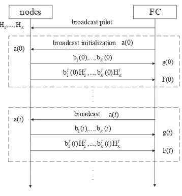
Based on the iterative process of the transceiver design, the conventional signaling procedure can be illustrated as Fig. 2. (a).
The training process of conventional signaling procedure can be mainly divided into the following steps.
. CSI acquisition: Each node sends a pilot to the FC in turn to estimate its global CSI.
. Algorithm operation: The iterative algorithm of the transceiver optimization is executed at the FC.
. Optimal results acquisition: The FC sends the correspond-ing optimal transmit vector to each node in turn. According to the signaling procedure, we derive the training complexity of the conventional signaling procedure in the following.
Proposition 1 (Training Complexity of Conventional Signal-ing Procedure). The conventional signaling procedure takes at least 2NtK time slots.
Proof:As shown in Fig. 2. (b), each node first transmits
nodes FC
. . .
iteration pilot
pilot
pilot
1
H
1
b
2
b
. . .
bK
2
H
HK
(a) Conventional Signaling Procedure
Uplink Pilot
...
Coherence Training Time Slots
Downlink Transmit Vector Uplink
Pilot
Uplink Pilot
Downlink Transmit Vector
Node1 Node2 ... NodeK
Downlink Transmit Vector ...
Node1 Node2 ... NodeK
[image:6.612.354.533.58.251.2](b) Conventional Training Time Slots
Fig. 2. Schematic diagram of conventional signaling procedure and training time slots.
B. Proposed Signaling Procedure
The analysis above indicates that the training complexity of the conventional signaling procedure is linear increasing with the number of nodes K. It will cause serious latency with massive nodes. Note that the FC only needs the combination of global CSI instead of individual CSI in (11), and the optimal transmit vectorbk of nodekis only related to its own global CSI in (12). As illustrated in Fig. 3. (a), we propose the over-the-air signaling procedure to reduce the training complexity. The training process of the over-the-air signaling procedure can be roughly divided into two steps.
. Individual CSI acquisition of nodes: The FC broadcasts a pilot to estimate their own CSI.
. Transceiver optimization iteration: The iterative algorithm continues until meets the specific condition. The details are illustrated as Algorithm 1.
To introduce the proposed signaling procedure more specif-ically, we provide the iteration process in details as follows. In each iteration, the FC broadcasts the current receive vectorato all nodes so that the current optimal transmit vectorbk can be obtained through (12). Later, the FC would obtain the effective CSI vector gwhen all nodes send the pilot1simultaneously, which can be expressed as
g=
K
∑
k=1
Hkbk. (18)
nodes FC
. . .
broadcast pilot
g(0)
1
b (0),..., b (0)K
broadcast initialization
1 1
b (0) H ,..., b (0) HT T T T
K K
F(0)
g( )i
1
b ( ),..., b ( )i Ki
broadcast a( )i
1 1
b ( ) H ,..., b ( ) HT T T T
K K
i i
F( )i
a(0)
a( )i
1
H ,..., HK
. . .
a(0)
(a) Over-the-Air Signaling Procedure
Downlink Pilot
Downlink Receive
Vector
Uplink Effective
Pilot ...
... Coherence Training Time Slots
Downlink Receive
Vector
Uplink Effective
Pilot ...
Node1ЊK Node1ЊK Node1ЊK ... Node1ЊK Node1ЊK ...
(b) Over-the-Air Training Time Slots
Fig. 3. Schematic diagram of over-the-air signaling procedure and training time slots.
Similarly, the effective CSI matrix F is obtained by sending the pilotbTkHTk where
F=
K
∑
k=1
HkbkbTkHTk. (19)
The FC can obtain its optimal receive vectora at the current iterative time through bringing effective CSI (18) and (19) into (11).
In conclusion, we illustrate the optimal transceiver as
a=(σ2nI+F)−1g, (20)
bk =(HTkaaTHk+µkI)−1HTka, (21)
whereµk satisfies
µk
[
tr(bTkbk)−Pk
]
= 0. (22)
The values of µk are either positive such that the power constraint holds or zero. The details of the iterative algorithm are shown in Algorithm 1, which elaborate the updating process of the Lagrange multipliers µk, the receive vectora and the transmit vector bk during each iterative time. The iteration continues until stopping criterion can be met. We analyze the training complexity of the over-the-air signaling procedure in the following.
[image:6.612.69.277.61.273.2]Procedure). Assuming the number of iterative times isNiter, the number of essential time slots of the over-the-air signaling procedure is Nr+ (1 + 2Nr)Niter.
Proof: As shown in Fig. 3. (b), the first process of
broadcasting pilot vector would take at least Nr time slots. During each iterative time, we spend one time slot to estimate the effective CSI vector g in (18) and Nr time slots for the effective CSI matrix F in (19). The optimal receive vector a should be broadcasted to all nodes, which would consume anotherNrtime slots. Thus, it would takeNr+(1+2Nr)Niter time slots for training process.
Obviously, the training complexity is irrelevant with the number of nodes K. It is caused by utilizing the broadcast-ing property, the reciprocity property and the superposition property of MAC to obtain the effective CSI. Through the simulation results, the number of iterative times Niter is positively increasing with the number of nodes K. However, it grows significantly slower than the conventional design.
We compare the two signaling procedures to elaborate the corresponding performance in the following.
Remark 1 (Training Complexity Comparison). The conven-tional signaling procedure takes 2NtK times slots, while the over-the-air signaling procedure requiresNr+(1+2Nr)Niter. The training complexity of the proposed scheme is positively correlated with the number of nodesKbut grows slower than the conventional scheme. There exists an intersection point with the corresponding number of nodes M = [Nr+ (1 +
2Nr)Niter]/2Nt. The over-the-air signaling procedure shows superior performance when K > M.
For more intuitive comparison of the training complexity, we use a system composed of K = 100 active nodes as an example. Each node and the FC are equipped withNt=Nr=
2 antennas. According to the simulation results in Section VI, the conventional scheme demands 2NtK = 400 time slots. The number of iterative times satisfiesNiter≤15so that the required time slots of the over-the-air signaling procedure is
Nr+ (1 + 2Nr)Niter= 77, which is19%of the conventional scheme. Moreover, the gap between the two training methods becomes larger with the growth of the number of nodes.
In each iterative time of the proposed algorithm, the MSE is reduced by the transceiver results updating. Since the MSE is lower bounded by zero, the convergence of Algorithm 1 can be guaranteed. Nevertheless, it is difficult to ensure the global convergence caused by its non-convex optimization.
V. ROBUSTDESIGN WITHIMPERFECTCSI
In this section, we present the transceiver design for han-dling CSI uncertainty in a robust manner with the conventional method and the proposed design, which are discussed under the expectation-based robust model and the worst-case robust model.
The above transceiver design is based on the global accurate CSI for all nodes and the FC. Since it is difficult to obtain accurate CSI in wireless communications, which is originated from a variety of sources, e.g., imperfect channel estimation,
Algorithm 1 Training Procedure for Over-the-Air Signaling Procedure
Input: Hk,Initializationa(0) Output: a,bk,µk
1: number of iteration time n= 0.
2: Initialize a= a(0).
3: Update a,bk,µk:
4: repeat
5: Update bk(n)based on Equation (21), k= 1,2, ..., K
6: Update g(n+ 1)based on Equation (18)
7: Update F(n+ 1)based on Equation (19)
8: Update a(n+ 1) based on Equation (20)
9: Update µk(n+ 1) based on Equation (22), k =
1,2, ..., K 10: n←n+ 1
11: until converge
feedback quantization, and delay in CSI acquisition on fading channels, we propose the robust design.
In the conventional signaling procedure, CSI is represented by the individual estimated channel for each node as defined below.
Definition 5(Robust CSI Model with Conventional Signaling Procedure). In the conventional signaling procedure, the CSI uncertainty model can be expressed as
ˆ
CSI= ˆHk, k = 1,2, ..., K,
∆CSI= ∆Hk, k= 1,2, ..., K,
(23)
whereHˆk denotes the nominally global CSI available at both sides, and ∆Hk is the estimated channel uncertainty at FC.
Similarly, we can model the CSI uncertainty with the over-the-air signaling procedure.
Definition 6(Robust CSI Model with Over-the-Air Signaling Procedure). In the over-the-air signaling procedure, the esti-mated uncertainty of the effective CSI contains two parts. The one is the effective CSI vector uncertainty via (19) as
ˆ
CSI1= ˆF= K
∑
k=1
HkbkbTkH T k,
∆CSI1= ∆F,
(24)
and the other one is the effective CSI matrix uncertainty via (18)
ˆ
CSI2= ˆg=
K
∑
k=1 Hkbk,
∆CSI2= ∆g,
(25)
whereHk denotes the available individual CSI at node k, Fˆ andgˆ are the nominal effective CSI only available at FC, and ∆F,∆grepresent the estimated uncertainty at FC.
transceiver design with the conventional scheme and the over-the-air signaling procedure under the expectation-based and the worst-case robust models.
A. Expectation-Based Robust Design with Conventional Sig-naling Procedure
According to the robust model in (23), the optimization of MSE with the conventional signaling procedure under the expectation-based robust model in P2 can be expressed as
P4 : min a,bk
MSE|Hkˆ
s.t.∥bk∥ 2≤
Pk, k= 1,2, ..., K,
(26)
where
MSE|Hkˆ =
K
∑
k=1
∥aTHkbkˆ −1∥2+σ2n∥aT∥2
+σ2h∥aT∥2 K
∑
k=1 ∥bk∥2,
(27)
and ∆Hk satisfies E{∆Hk} = 0Nr×Nt, the second-order statistics of ∆Hk satisfies E
{
∆Hk·∆HTk
}
= σ2
hINr, and
E{∆Hk·∆HTj
}
=0Nr×Nr,k̸=j.
Since MSE|Hkˆ is not jointly convex on transmit vector a and receive vector bk, the similar iterative algorithm of P1 can be adopted to find the optimal transceiver.
According to the problem formulation in P4, the Lagrange dual objective function can be constructed as
L(a,bk, µk) =MSE|Hˆk+ K
∑
k=1
µk
(
bTkbk−Pk
)
, (28)
whereµk is the Lagrange multiplier associated with the power constraint of the node k.
Proposition 3(Optimal Robust Transceiver with Conventional Signaling Procedure). The expression of the optimal transmit vectors and receive vector can be formulated as
a=
[ σn2I+
K
∑
k=1
(
HkbkbTkHTk+σh2bTkbkI)
]−1(K
∑
k=1 Hkbk
) ,
(29) bk=(HTkaaTHk+µkI+σh2aTaI)−1HTka, k= 1,2, ..., K,
(30) whereµk ≥0 and satisfies
µk
[
tr(bTkbk)−Pk
]
= 0, k= 1,2, ..., K. (31)
Proof: Taking the partial derivative of L with respect to
the receive vectoraand transmit vectorbkand using the KKT conditions, we can obtain the optimality conditions as shown in (29) and (30).
B. Expectation-Based Robust Design with Over-the-Air Sig-naling Procedure
In this part, we assume that the CSI uncertainty is originated from the same source for analytic convenience. It implies that the elements of uncertainty matrixFand vectorgsatisfy the same distribution. We can model the CSI error as
Fi= ˆFi+∆i, i= 1,2, ..., Nr,
g= ˆg+∆Nr+1,
(32)
where ∆ denotes the channel uncertainty sets matrix, Ai is the column vector of matrixA,∆isatisfiesE{∆i}=0Nr×1,
E{∆i·∆Ti
}
=σ2hINr, andE
{
∆i·∆Tj
}
=0Nr×Nr,i̸=j,
i= 1,2, ..., Nr+ 1.
According to (32), the expectation-based robust design in P2 can be written as
P5 : min a,bk
MSE|
⟨
ˆ
F,gˆ
⟩
s.t.∥bk∥2≤Pk, k= 1,2, ..., K,
(33)
where
MSE|
⟨
ˆ
F,ˆg
⟩
=E{aTFa−aTg−agT+K+σ2naTa}
=aTFaˆ −aTˆg−agˆT +K+σn2aTa
+E
{N
r
∑
i=1
aT∆iai−aT∆Nr+1−a∆ T Nr+1
} .
(34) The CSI uncertainty variable∆i is a zero mean variable so that MSE|
⟨
ˆ
F,ˆg
⟩
can be formed as
MSE|
⟨
ˆ
F,gˆ
⟩
=aTFaˆ −aTˆg−agˆT +K+σn2aTa. (35)
The same structure of (35) and (9) makes the method of transceiver design under perfect CSI being totally applicable for P5. Thus, we can obtain the expression of the transceiver utilizing the Lagrange dual objective function which is
L(a,bk,µk) =MSE|
⟨
ˆ
F,ˆg
⟩
+
K
∑
k=1
µk
(
bTkbk−Pk
) , (36)
whereµkis the Lagrange multiplier associated with the power constraint of the node k.
Proposition 4 (Optimal Robust Transceiver with Over-the-air Signaling Procedure). The expression of the optimal transmit vectors and receive vector can be formulated as
a=
(
σ2nI+ ˆF
)−1
ˆ
g, (37)
bk=
(
HTkaaTHk+µkI
)−1
HTka, k= 1,2, ..., K, (38)
µk
[
tr(bTkbk)−Pk
]
= 0, k= 1,2, ..., K. (39)
Proof: Similar to the optimization in P4, we take the
partial derivative of L(a,bk,µk) with respect to the receive vectoraand transmit vectorbkand using the KKT conditions, the optimality conditions can be obtained as (37) and (38).
Similarly, the results can be obtained via iterative algorithm under the perfect CSI. The iterative algorithm will stop under a specific condition. The transceiver design can improve the MSE performance than the conventional scheme due to the noise averaging effect, which is illustrated by simulation results in Section VI.
C. Worst-Case Robust Design with Conventional Signaling Procedure
In section III, we indicate that the statistical properties of the CSI uncertainties are no longer suitable to guarantee the MSE constraints exactly. An alternative robust model is developed to maximize the performance under the worst channel uncertainty and known as the worst-case model.
According (24) and (25), the optimization of MSE for P3 can be formulated as
P6 : min a,bk
max
∆Hk
MSE|Hkˆ ,
s.t. ∥bk∥2≤Pk, k= 1,2, ..., K,
∥∆Hk∥2≤σ2h, k= 1,2, ..., K,
(40)
where ∥∆Hk∥2 ≤ σ2h denotes the constraint of uncertainty set, and MSE|Hˆk is the MSE under estimated CSI which can be formed as
MSE|Hˆk= K
∑
k=1
∥aT( ˆHk+ ∆Hk)bk−1∥2+σn∥2 aT∥2.
(41)
To simplify the objective function, we rewrite P6 into
P7 : min a,bk
max
∆Hk K
∑
k=1
tk+σn∥2 aT∥2
s.t. ∥bk∥2≤Pk, k= 1,2, ..., K,
∥∆Hk∥2≤σ2h, k= 1,2, ..., K,
∥aT( ˆHk+ ∆Hk)bk−1∥2≤tk.
(42)
To handle the channel uncertainty matrix into an available manner, we introduce new variables via an important tool in robust optimization, which is known as the S-procedure and primarily generalized as follows.
Lemma 1 (S-procedure). Let θm(ϵ) = ϵTZmϵ +zTmϵ+
ϵTzm+ ˜zm,m= 1,2 be two quadratic functions inϵ and let Zmbe Hermitian. Suppose there existsˆϵsuch thatθ1(ˆϵ)>0 , then the implication [25] [26]
θ1(ϵ)≥0⇒θ2(ϵ)≥0, (43)
holds true if and only if there exists λ≥0 such that
[
Z2 z2
z2T z˜2
]
−λ [
Z1 z1
z1T z˜1
]
≽0. (44)
Let θ1(ϵ) ≥ 0 describe the ∆Hk constraint and let
θ2(ϵ) ≥ 0 describe MSE constraint specifically, and the channel uncertainty constraint and the MSE constraint can be combined into a second-order cone constraint which is convex. If suchλ≥0 exists, the transceiver design can hold the MSE constraint for all points in the channel uncertainty set, even for the worst channel uncertainty condition. Based on it, we convert the channel uncertainty constraint holding into positive variableλfinding.
To solve the challenge of the non-convex objective function over aT,bk, we adopt the iterative algorithm to find the optimal solution.
In conclusion, the P7 is varied as follows.
Proposition 5 (Equivalent Convex Robust Design Problem with Conventional Signaling Procedure). For a fixed receive vectora, P7 is equivalent to P7.1
P7.1 : min bk,λk
K
∑
k=1
tk+σ2n∥aT∥2
s.t. [
λkINtNr−ϕkϕ T
k −ϕkυTk −υkϕTk tk−∥υk∥2−λkσh2
]
≽0,
λk ≥0, k= 1,2, ..., K.
(45) where
υk =aTHkbkˆ −1,
ϕTk =vec(abTk). (46)
For fixed transmit vectorsbk,k= 1,2, ..., K, the optimization of P7can be formulated as the similar form to P7.1 and defined as P7.2. The main idea of the transceiver design is to find the optimal receive vector a via fixed transmit vectors bk, and vise versa with the iteration between P7.1 and P7.2.
Proof: Denote the channel uncertainty constraint and
MSE constraint asθ1(ζk)≥0 andθ2(ζk)≥0respectively,
θ1(ζk) =−ζ T
kINtNrζk+σh2,
θ2(ζk) =−ζ T kϕkϕ
T kζk−ζ
T kϕkυ
T
k−υkϕTkζk+tk−∥υk∥2, (47) where
ζk =vec(∆Hk), (48)
Thereby, we raise a robust MSE minimization algorithm with iteratively a,bk and slack variablesλk under the worst-case model. The iterative process will stop under a specific condition. We give a brief derivation regarding the computa-tional time complexity of employing S-procedure method.
Proposition 6 (Computational Time Complexity of Conven-tional Signaling Procedure). The computational time complex-ity is O(K72).
Proof: The constraints in (45) satisfy the real-valued
standard SDP form [28]
min x∈Rn
mTx:A0+
n
∑
j=1
xjAj≽0
, (49)
where Aj are symmetric block-diagonal matrices with K
diagonal blocks of sizes ai×ai, where ai = Nt×Nr+ 1.
n = K+Nt represents the number of unknown variables, where the first term of n represents the number of slack variables λk and the second corresponds the length of the receive vector. The number of arithmetic operations for the termination of interior point methods that solve this problem is known to be upper bounded by
O
(
1 +
K
∑
i=1
ai
)1 2
n (
n2+n
K
∑
i=1
ai2+ K
∑
i=1
ai3
) . (50)
Based on it, the computational time complexity is about O(K72)which is the highest order in (50).
We introduce K extra variables to represent the worst channel condition utilizing S-procedure, and adopt the iterative algorithm to transform the optimization into a convex prob-lem. The MSE performance is shown through simulations in Section VI.
D. Worst-Case Robust Design with Over-the-Air Signaling Procedure
In the over-the-air signaling procedure, the effective CSI uncertainty model in (32) is assumed to satisfy ∥∆i∥2≤σ2h. The optimization of MSE at the FC can be written as
P8 : min a,bk
max ∆i
MSE|
⟨
ˆ
F,gˆ
⟩
s.t.tr(bkbTk)≤Pk, k= 1,2, ..., K,
∥∆i∥2≤σ2h, i= 1,2, ..., Nr+ 1, (51)
where
MSE|
⟨
ˆ
F,gˆ
⟩
=E{aTFa−aTg−agT +K+σn2aTa}
=aTFaˆ −aTˆg−agˆT +K+σn2aTa
+
(N
r
∑
i=1
aT∆iai
)
−aT∆Nr+1−∆TNr+1a.
(52)
Similar to P7, the challenges to resolve P8 include the un-certain worst channel condition and the non-convex objective function. Based on the analysis above, we can rebuild P8 utilizing S-procedure as follows.
Proposition 7 (Equivalent Convex Robust Design Problem with Over-the-Air Signaling Procedure). For fixed transmit vectorsbk,k= 1,2, ..., K, P8is equivalent to
P8.1 : min a,λi
N∑r+1
i=1
ti+MSE0 (53a)
s.t. [
λNr+1INr a
aT t
Nr+1−λNr+1σ 2 h
]
≽0,
(53b)
[
λiINr − 1 2aia −1
2aia T t
i−λiσ2h
]
≽0, i= 1,2, ..., Nr,
(53c)
λi≥0, i= 1,2, ..., Nr+ 1. (53d)
where
MSE0=aTFaˆ −aTˆg−agˆT +K+σn2a Ta.
(54)
For a fixed receive vector a, P8 can be formulated as
P8.2 : min bk
MSE0
s.t.∥bk∥2≤Pk, k= 1,2, ..., K,
(55)
which is convex overbk and the optimal transmit vectors can be defined as
bk=
(
HTkaaTHk+µkI
)−1
HTka, k= 1,2, ..., K,
µk
[
tr(bTkbk)−Pk
]
= 0, k= 1,2, ..., K, (56)
whereµk≥0.
Proof:For fixed transmit vectorsbk,k= 1,2, ..., K, the uncertainty estimated channel constraint and the MSE con-straint can be expressed asθ1(∆Nr+1)≥0andθ2(∆Nr+1)≥ 0, where
−aT∆Nr+1−a∆ T
Nr+1≤tNr+1,
θ1(∆Nr+1) =−∆ T
Nr+1INr∆Nr+1+σ 2 h,
θ2(∆Nr+1) =a T∆N
r+1+a∆ T
Nr+1+tNr+1.
(57)
If there exists λNr+1 ≥ 0 such thatθ1(∆Nr+1)≥0 ⇒
θ2(∆Nr+1)≥0holds true, we can obtain the SDP constraint in (53b).
For the other uncertainty estimated channel constraints ∥∆i∥2
≤ σh2, i = 1,2, ..., Nr, the uncertainty channel constraints and the MSE constraints can be expressed as
aT∆iai≤ti, i= 1,2, ..., Nr,
θ1(∆i) =−∆Ti INr∆i+σ 2 h,
θ2(∆i) =−
1 2aia
T∆i−1
2ai∆
T ia+ti.
(58)
Similarly, the constraints of ∆i can be expressed as the SDP constraints in (53c).
Based on the above statement, we can achieve the convex optimization for receive vector under fixed transmit vectors.
If the receive vector a is fixed, the optimization of bk is irrelevant with ∆i in P8, which results in that the objective function of the optimization in P8 is equals to MSE0, and the P8 becomes the convex optimization for fixed receive vector a in (55). The Lagrange dual objective function can be constructed as
L(bk,µk) =MSE0+ K
∑
k=1
µk(bTkbk−Pk), (59)
where the Lagrange multiplierµkis associated with the power constraint of transmitterk.
According to the KKT conditions given as
tr(bTkbk
)
−Pk≤0, k= 1,2, ..., K,
µk≥0, k= 1,2, ..., K,
µk
[
tr(bTkbk)−Pk
]
= 0, k= 1,2, ..., K,
∂L
∂bk = 0, k= 1,2, ..., K,
(60)
we take the partial derivative of L with the respect to the vector bk and obtain optimal transmit vectors in (56).
Proposition 8 (Computational Time Complexity of
Over-the-Air Signaling Procedure). The computational time complexity of the over-the-air signaling procedure is about O(Nr6).
Proof: Due to the fact that the constraints of P8 in (53)
are SDP which contain Nr+ 1blocks of sizes ai =Nr+ 1, the complexity is upper bounded by
O
(
1 +
N∑r+1
i=1
ai
)1 2
n (
n2+n
N∑r+1
i=1
ai2+ N∑r+1
i=1
ai3
) ,
(61)
The unknown vector to be determined is of size n = Nr+
(Nr+ 1), where the first corresponds the receive vector of lengthNrand the second represents the number of slack vari-ablesλkequals toNr+1. The highest order in the polynomial isNr6. Therefore, the computational time complexity is about O(Nr6). The optimization in (56) is simple multiplication, whose computational time complexity can be ignored.
Based on (50) and (61), we compare the conventional design and the over-the-air signaling procedure in the following.
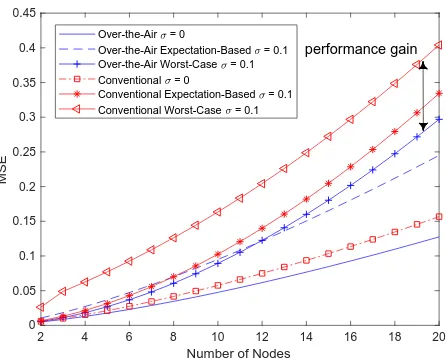
2 4 6 8 10 12 14 16 18 20
Number of Nodes 0
0.05 0.1 0.15 0.2 0.25 0.3 0.35 0.4 0.45
MSE
Over-the-Air = 0
Over-the-Air Expectation-Based = 0.1 Over-the-Air Worst-Case = 0.1 Conventional = 0
Conventional Expectation-Based = 0.1 Conventional Worst-Case = 0.1
performance gain
Fig. 4. MSE performance with different number of nodes of 2×2 channel matrix and SNR = 30dB.
Remark 2 (Computational Time Complexity Comparison). The computational time complexity of the conventional scheme is aboutO(K72), which is extremely increasing with
massive nodes. Compared with the conventional design, the computational time complexity of the over-the-air signaling procedure is about O(Nr6). When the number of nodes K satisfies K ≫ Nr, the robust design with the over-the-air signaling procedure significantly reduces the computational time complexity.
VI. SIMULATIONRESULTS ANDDISCUSSION
[image:11.612.325.548.64.243.2]In this section, we illustrate the performance of the proposed algorithms through simulations. Each transmitter is limited by the same transmit power constraint. The locations of the users satisfy the random distribution. With the normalization of the large-scale fading and the consideration of the small-scale fading, a quasi-static flat Rayleigh fading channel is used, which is modeled as independently and identically distributed (i.i.d) Gaussian random variables with zero mean and unit variance. We set the initialization receive vector asb=1.
Fig. 4 shows the MSE performance for different numbers of nodes. This agrees with our intuition that more connected nodes makes it harder to design one common receive beam-former to equalize all channels. The MSE performance of the over-the-air signaling procedure is obviously better than the conventional scheme with numerous nodes, which is caused by noise averaging effect. The performance gap between two designed schemes increases with the growth of the number of nodes.
We evaluate the MSE performance as a function of
signal-to-noise ratio(SNR) in Fig. 5. It can be seen that the
[image:11.612.59.300.588.629.2]0 5 10 15 20 25 30 35 40 45
SNR/dB
0 0.1 0.2 0.3 0.4 0.5 0.6
MSE
Over-the-Air = 0
Over-the-Air Expectation-Based = 0.1 Over-the-Air Worst-Case = 0.1 Conventional = 0
[image:12.612.322.549.64.245.2]Conventional Expectation-Based = 0.1 Conventional Worst-Case = 0.1
Fig. 5. MSE performance with different SNR of 2×2 channel matrix and the number of nodes = 2.
2 4 6 8 10 12 14
Number of Receive Antennas
0 0.01 0.02 0.03 0.04 0.05 0.06
MSE
Over-the-Air = 0
Over-the-Air Expectation-Based = 0.1 Over-the-Air Worst-Case = 0.1 Conventional = 0
Conventional Expectation-Based = 0.1 Conventional Worst-Case = 0.1
Fig. 6. MSE performance with different number of receive antenna number of 2 nodes and SNR = 30dB.
for the most conditions. It also verifies the conclusion that the over-the-air signaling procedure outperforms the conventional scheme on the MSE performance. Although the proposed algorithm is not guaranteed to converge to global optimal solutions, the simulations show that it quickly converges and the proposed algorithm is not sensitive to initialization.
Fig. 6 and Fig. 7 illustrate the MSE performance of the dif-ferent number of receive antennasNr and number of transmit antennas Nt. The MSE performance increases with not only the number of receive antennas Nr but also the number of transmit antennasNt. Deploying multi-antennas provide extra channel gain and compensate for the performance degradation via space diversity.
We show the MSE performance with different channel uncertainty varianceσin Fig. 8. With the increases of channel uncertainty variance, the MSE performance of both robust designs are decreased. However, the robust design of the over-the-air signaling procedure performs lower MSE than
2 4 6 8 10 12 14
Number of Transmit Antennas
0 0.01 0.02 0.03 0.04 0.05 0.06 0.07 0.08
MSE
Over-the-Air = 0
Over-the-Air Expectation-Based = 0.1 Over-the-Air Worst-Case = 0.1 Conventional = 0
[image:12.612.65.285.64.244.2]Conventional Expectation-Based = 0.1 Conventional Worst-Case = 0.1
Fig. 7. MSE performance with different number of transmit antenna number of 2 nodes and SNR = 30dB.
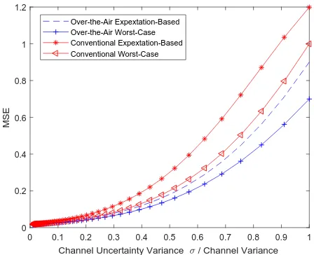
0 0.1 0.2 0.3 0.4 0.5 0.6 0.7 0.8 0.9 1
Channel Uncertainty Variance / Channel Variance
0 0.2 0.4 0.6 0.8 1 1.2
MSE
Over-the-Air Expextation-Based Over-the-Air Worst-Case Conventional Expextation-Based Conventional Worst-Case
Fig. 8. MSE performance with different channel uncertainty variance of 2 nodes and SNR = 30dB.
the conventional design. The performance gap between the conventional design and the proposed method also becomes deep with the increases of uncertain variance, which is caused by noise averaging effect.
[image:12.612.324.548.300.482.2] [image:12.612.61.287.301.480.2](a)
1 2 3 4 5 6 7 8 9 10 11 12 13 14 15
Iterative Times
0 0.02 0.04 0.06 0.08
Frequency Iterative Times Statistics Pseudo-Random Number Statistics
0 50 100 150 200 250 300 350 400
Number of Nodes
0 500 1000 1500 2000
Training Complexity - Time Slots
(b)
Over-the-Air Signaling Procedure Conventional Signaling Procedure
[image:13.612.59.287.62.244.2]M
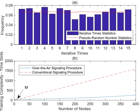
Fig. 9. (a) is the distribution of iterative times for 2×2 channel matrix. Number of nodes = 100 and SNR = 30dB. It is based on the over-the-air signaling procedure under perfect CSI. (b) is the training time slots of the conventional scheme and the over-the-air signaling procedure
point M for the conventional scheme and the over-the-air signaling procedure, and the proposed signaling procedure extremely reduces training complexity after the cross point. The simulation results support our previous analysis in Section IV that the training complexity of the proposed solution is significantly reduced for the massive CSI acquisition. Thereby, the proposed solution features low complexity and is preferred in the networks with large scale nodes.
VII. CONCLUSIONS
In this paper, we have proposed a robust design for massive CSI acquisition in analog function computation networks. The over-the-air signaling procedure has been proposed to solve the excessive latency problem of the conventional design. The training complexity of the conventional signaling proce-dure and the proposed one have been developed and further compared. The robust design under the expectation-based model and the worst-case model have also been discussed for both the conventional scheme and the proposed signaling procedure. Moreover, we have provided the computational time complexity analysis. We have derived the conclusion that the training complexity has been significantly reduced for the proposed signaling procedure via the defined effective CSI, and its corresponding transceiver optimization has behaved lower computational time complexity than the conventional design. Simulation results have shown that the transceiver design with the over-the-air signaling procedure has improved MSE performance owing to the noise averaging effect.
REFERENCES
[1] G. T. V14.2.0, “Study on scenarios and requirements for next generation access technologies,”3rd Generation Partnership Project (3GPP), 2017. [2] O. Abari, H. Rahul, and D. Katabi, “Over-the-air function computation
in sensor networks,”arXiv preprint arXiv:1612.02307, 2016.
[3] B. Nazer and M. Gastpar, “Computation over multiple-access channels,”
IEEE Trans. Inf. Theory, vol. 53, no. 10, pp. 3498–3516, 2007.
[4] ——, “Compute-and-forward: Harnessing interference through struc-tured codes,”IEEE Trans. Inf. Theory, vol. 57, no. 10, pp. 6463–6486, 2011.
[5] J. Zhan, B. Nazer, U. Erez, and M. Gastpar, “Integer-forcing linear receivers,” IEEE Trans. Inf. Theory, vol. 60, no. 12, pp. 7661–7685, 2014.
[6] M. Goldenbaum, H. Boche, and S. Sta´nczak, “Harnessing interference for analog function computation in wireless sensor networks,” IEEE Trans. Signal Process, vol. 61, no. 20, pp. 4893–4906, 2013. [7] ——, “Nomographic functions: Efficient computation in clustered
Gaus-sian sensor networks,”IEEE Trans. Wireless Commun., vol. 14, no. 4, pp. 2093–2105, 2015.
[8] R. C. Buck, “Approximate complexity and functional representation,”
Journal of Mathematical Analysis & Applications, vol. 70, no. 1, pp. 280–298, 1976.
[9] F. Wu, L. Chen, N. Zhao, Y. Chen, F. R. Yu, and G. Wei, “Computation over wide-band mac: Improved achievable rate through sub-function allocation,”arXiv:1806.08632, 2018.
[10] M. Goldenbaum and S. Sta´nczak, “Robust analog function computation via wireless multiple-access channels,”IEEE Trans. Commun, vol. 61, no. 9, pp. 3863–3877, 2013.
[11] A. Kortke, M. Goldenbaum, and S. Sta´nczak, “Analog computation over the wireless channel: A proof of concept,”SENSORS, pp. 1224–1227, 2014.
[12] M. Goldenbaum, S. Stanczak, and H. Boche, “On achievable rates for analog computing real-valued functions over the wireless channel,”IEEE International Conference on Communications (ICC), pp. 4036–4041, 2015.
[13] S. Sigg, P. Jakimovski, and M. Beigl, “Calculation of functions on the rf-channel for iot,”International Conference on Internet of Things (IOT), pp. 107–113, 2012.
[14] O. Abari, H. Rahul, D. Katabi, and M. Pant, “Airshare: Distributed coherent transmission made seamless,”IEEE Conference on Computer Communications (INFOCOM), pp. 1742–1750, 2015.
[15] L. Chen, X. Qin, and G. Wei, “A uniform-forcing transceiver design for over-the-air function computation,”IEEE Wireless Communications Letters, vol. 7, no. 6, pp. 942–945, 2018.
[16] G. Zhu, L. Chen, and K. Huang, “Over-the-air computation in MI-MO multi-access channels: Beamforming and channel feedback,”arXiv preprint arXiv:1803.11129, 2018.
[17] L. Chen, N. Zhao, Y. Chen, F. R. Yu, and G. Wei, “Over-the-air com-putation for cooperative wideband spectrum sensing and performance analysis,”IEEE Transactions on Vehicular Technology, vol. 67, no. 11, pp. 10 603–10 614, 2018.
[18] A. Tajer, N. Prasad, and X. Wang, “Robust linear precoder design for multi-cell downlink transmission,”IEEE Trans. Signal Process, vol. 59, no. 1, pp. 235–251, 2011.
[19] E. Bj¨ornson, G. Zheng, M. Bengtsson, and B. Ottersten, “Robust monotonic optimization framework for multicell miso systems,” IEEE Trans. Signal Process, vol. 60, no. 5, pp. 2508–2523, 2012.
[20] N. Vucic, H. Boche, and S. Shi, “Robust transceiver optimization in downlink multiuser mimo systems,”IEEE Trans. Signal Process, vol. 57, no. 9, pp. 3576–3587, 2009.
[21] N. K. Venkategowda, B. B. Narayana, and A. K. Jagannatham, “Precod-ing for robust decentralized estimation in coherent-mac-based wireless sensor networks,”IEEE Trans. Signal Process. Lett, vol. 24, no. 2, pp. 240–244, 2017.
[22] J. Huang, Q. Zhang, Q. Li, and J. Qin, “Robust parallel analog function computation via wireless multiple-access mimo channels,”IEEE Trans. Signal Process .Lett, vol. 22, no. 9, pp. 1297–1301, 2015.
[23] A. B. Gershman, N. D. Sidiropoulos, S. Shahbazpanahi, M. Bengtsson, and B. Ottersten, “Convex optimization-based beamforming,” IEEE Signal Process Mag., vol. 27, no. 3, pp. 62–75, 2010.
[24] S. A. Vorobyov, A. B. Gershman, and Z.-Q. Luo, “Robust adaptive beamforming using worst-case performance optimization: A solution to the signal mismatch problem,” IEEE Trans. Signal Process, vol. 51, no. 2, pp. 313–324, 2003.
[25] S. Boyd and L. Vandenberghe, Convex optimization. Cambridge university press, 2004.
[26] S. Boyd, L. El Ghaoui, E. Feron, and V. Balakrishnan,Linear matrix inequalities in system and control theory. Siam, 1994, vol. 15. [27] H. Shen, B. Li, M. Tao, and X. Wang, “Mse-based transceiver designs
for the mimo interference channel,” IEEE Trans. Wireless Commun., vol. 9, no. 11, pp. 3480–3489, 2010.
Fan Angreceived the B.S. degree in information and communications engineering from Xi’an Jiaotong University, Xian, China, in 2017. She is currently pursuing the M.S. degree with the Department of Electronic Engineering and Information Science, U-niversity of Science and Technology of China. Her research interests include wireless IoT communica-tions and federated learning.
Li Chenreceived the B.E. in electrical and informa-tion engineering from Harbin Institute of Technolo-gy, Harbin, China, in 2009 and the Ph.D.degree in electrical engineering from the University of Science and Technology of China, Hefei, China, in 2014. He is currently a faculty member with the Department of Electronic Engineering and Information Science, University of Science and Technology of China. His research interests include wireless IoT communica-tions and wireless optical communicacommunica-tions.
Nan Zhao(S’08-M’11-SM’16) is currently an Asso-ciate Professor at Dalian University of Technology, China. He received the B.S. degree in electronics and information engineering in 2005, the M.E. de-gree in signal and information processing in 2007, and the Ph.D. degree in information and commu-nication engineering in 2011, from Harbin Institute of Technology, Harbin, China. His recent research interests include UAV Communications, Interference Alignment, and Physical Layer Security.
Dr. Zhao is serving or served on the editorial boards of 7 SCI-indexed journals. He received Top Reviewer Award from IEEE Transactions on Vehicular Technology in 2016, and was nominated as an Exemplary Reviewer by IEEE Communications Letters in 2016. He won the best paper awards in IEEE VTC’2017-Spring and MLICOM 2017.
Yunfei Chen(S’02-M’06-SM’10) received his B.E. and M.E. degrees in electronics engineering from Shanghai Jiaotong University, Shanghai, P.R.China, in 1998 and 2001, respectively. He received his Ph.D. degree from the University of Alberta in 2006. He is currently working as an Associate Professor at the University of Warwick, U.K. His research interests include wireless communications, cognitive radios, wireless relaying and energy harvesting.