warwick.ac.uk/lib-publications
Original citation:Guo, Z., Tian, Yanling, Liu, Xianping, Wang, F., Zhou, C. and Zhang, D.. (2017) Modeling and simulation of the probe tip based nanochannel scratching. Precision Engineering, 49. pp. 136-145.
Permanent WRAP URL:
http://wrap.warwick.ac.uk/94042
Copyright and reuse:
The Warwick Research Archive Portal (WRAP) makes this work by researchers of the University of Warwick available open access under the following conditions. Copyright © and all moral rights to the version of the paper presented here belong to the individual author(s) and/or other copyright owners. To the extent reasonable and practicable the material made available in WRAP has been checked for eligibility before being made available.
Copies of full items can be used for personal research or study, educational, or not-for-profit purposes without prior permission or charge. Provided that the authors, title and full bibliographic details are credited, a hyperlink and/or URL is given for the original metadata page and the content is not changed in any way.
Publisher’s statement:
© 2017, Elsevier. Licensed under the Creative Commons
Attribution-NonCommercial-NoDerivatives 4.0 International http://creativecommons.org/licenses/by-nc-nd/4.0/
A note on versions:
The version presented here may differ from the published version or, version of record, if you wish to cite this item you are advised to consult the publisher’s version. Please see the ‘permanent WRAP URL’ above for details on accessing the published version and note that access may require a subscription.
Modeling and simulation of the probe tip based nanochannel scratching
Z. Guo
1, Y. Tian*
1,2, X. Liu
2, F. Wang
1, C. Zhou
1, D. Zhang
11
Key Laboratory of Mechanism Theory and Equipment Design of Ministry of Education, Tianjin University,
Tianjin 300072, China
2
School of Engineering, University of Warwick, Coventry CV4 7AL, UK
Abstract
This paper presents the theoretical modeling and numerical simulation of the probe tip based nanochannel
scratching. According to the scratching depth, the probe tip is modeled as a spherical capped conical tip or a
spherical capped regular three side pyramid tip to calculate the normal force needed for the nanochannel scratching.
In order to further investigate the impact of scratching speed, scratching depth and scratching direction on the
scratching process, the scratching simulation is implemented in LS-DYNA software, and a mesh-less method called
smooth particle hydrodynamics (SPH) is used for the sample construction. Based on the theoretical and simulated
analyses, the increase of the scratching speed, the scratching depth and the face angle will result in an increase in
the normal force. At the same scratching depth, the normal forces of the spherical capped regular three side
pyramid tip model are different in different scratching directions, which are in agreement with the theoretical
calculations in the d3 and d4 directions. Moreover, the errors between the theoretical and simulated normal forces
increase as the face angle increases.
Key words: tip modeling; nanochannel scratching; SPH; normal force.
1. Introduction
Nanochannels have wide applications in microfluidics technology, such as rapid DNA sequencing, drug
delivery, battery and nanofluidic transistor [1]. Among various methods of nanochannel fabrication, probe tip based
micro/nano scratching has been widely applied [2-6]. In the nanochannel scratching, the sample is usually mounted
on a piezoelectric actuated micro/nano positioning stage, which has many excellent advantages including fast
response time, large mechanical force and high positioning precision, there have been many investigations on the
modeling and control of this kind of stage [7]. As the cutting tool, the probe tip is pressed into the sample with a
desired depth, and then through the motion control of the precision positioning stage, the nanochannel can be
Various kinds of probe tip models have been developed in the past few years. According to the tip geometry,
they can be mainly categorized into spherical tips [8-10], conical tips [11, 12] and pyramidal tips [13-15]. The
spherical tip is usually with a diameter in the micron scale, which is not appropriate for the nanochannel fabrication.
For the conical tip and pyramidal tip, it is impossible to obtain an ideal sharp tip due to manufacturing errors and
tip wear, thus, these tips are usually modeled as a conical or pyramidal base with spherical cap. If only the spherical
cap is involved in the operation for the surface topography measurement and scratching, the tip is still modeled as a
sphere. However, in the scratching with large depth, the tip base will dominate the scratching process, so the tip
base must be considered in such kind of application. Although the spherical capped conical model has been widely
used, but it cannot substitute the pyramid structure. Geng proposed the spherical capped pyramidal tip model for
the AFM tip, and the tip-sample interface was analyzed for single scratching [13], but the calculation of the
horizontal projected area is complicated. Besides the AFM probe tip, the Berkovich probe has also been used for
scratching investigation, but the scratching direction was not be considered [14-16], this kind of tip has regular
pyramidal structure, which has many special geometry property compared with the general pyramidal structure,
such as equilateral triangle of horizontal cross-section.
As a supplementary means for theoretical analysis, the numerical simulation usually acts as the role of guiding
the experiments, and shows the possible phenomenon in the actual experiment. Molecular dynamics (MD) is an
efficient method for the investigation of the micro/nano scratching, and which has been adopted by many
researchers. Zhu et al investigated the effect of the scratching velocity on the scratching process in reference
[17-19]. Zhang explored the subsurface deformed layers in AFM-based nanometric cutting process through
molecular dynamics simulation [20]. Yan studied the effect of feed on the nano-scratching process using MD
simulation [21]. Zhang examined the influence of double-tip scratch on nano scratching process via MD [22]. Fang
researched the nanoscratch behavior of multi-layered films with MD [23]. However, in all these simulations, the
scratching depth was less than 10 nanometers, since a larger scratching depth will result in a very long simulation
time. Thus, MD is not an appropriate method for the simulation of dozens even hundreds nanometer scratching
depth.
Smooth particle hydrodynamic (SPH) is a mesh-less method based on Lagrangian method, which is firstly
proposed by Gingold and Monaghan in 1977 to solve the astrophysical problems [24], but with the development of
the method, it has been widely used in fluid simulation and solid mechanics for the advantages in dealing with the
recent years [27-29]. Zhao studied the effects of cutting process on residual stress distribution, and the effects of
residual stress on mechanism using SPH method [27], the cutting depth is from 300nm to 900nm. And then still
with SPH method, his team further investigated the residual stress on sequential scratching with smaller scratching
depth from 50nm to 150nm [28]. Cao compared the conventional scratching with the ultrasonic-assisted scratching
on the material removal process, two scratching depth 70nm and 2μm were simulated with SPH [29].
In the tip based nanochannel scratching, the normal force is an important parameter because it directly decides
the scratching depth, so this paper focuses on the theoretical calculation and the simulation of the normal force.
Among various probe tips, the three side pyramid probe tip is the most popular for the good machining ability, thus
a spherical capped regular three side pyramidal tip model is chosen to model this kind of tips in large scratching
depth. The geometrical model of the spherical capped conical tip and the spherical capped regular three side
pyramidal tip are firstly introduced in this paper, and then the horizontal projected areas of the tip-sample interfaces
are analyzed in section 2. The SPH simulation model are constructed in section 3, the effects of the scratching
parameters (scratching speed, scratching depth and scratching direction) and the face angle of the probe tip on the
scratching process are simulated and discussed in section 4.
2. The probe tip model and the horizontal projected area of the tip-sample interface
In this section, two probe tip models are presented, one is spherical capped conical tip model and the other is
spherical capped regular three side pyramidal tip model. The scratching depth considered in this paper is from
20nm to 200nm, and the spherical cap radius is assumed to be 90 nm. When the scratching depth is less than 60nm,
only the spherical cap takes part in the scratching, the former tip model has a complete spherical surface in this
range, so it is selected for the simulation in this scratching range. When the scratching depth is larger than 60nm,
the probe base will dominate the scratching, the latter tip model is more similar with the actual three side pyramid
probe tip in geometric features, so it is selected for the simulation in this range of scratching depth.
Fig. 1. Spherical capped conical tip model
R0
(a) (b) (c)
Fig. 2. (a) Spherical capped regular three side pyramidal tip model; (b) Section of the triangle ΔAO1O3; (c) Section of the triangle
ΔAO1C.
2.1 Geometrical model
A spherical capped conical tip model has been widely applied in the analysis of the tip-sample interface [10,
11], which is shown in Fig. 1, where R0 is the spherical cap radius and δ is the half angle. In precious paper, both
the spherical cap and the conical base are used for the scratching, but in this paper only the spherical cap is selected
for the small scratching depth under 60nm, the cone part is seen as the assumptive probe tip base, so the value of δ
does not affect the scratching process and the tip-sample interface.
For the large scratching depth from 60nm to 200nm, a spherical capped regular three side pyramidal tip model
is presented, as shown in Fig. 2(a). The point A is the hypothetical apex, and the triangle ΔBCD is the critical
horizontal section interface between spherical cap and pyramid base. The arcsBC, CDandBDare the intersection
of spherical surface and pyramidal surfaces, which are assumed to be tangent to the pyramidal edges. Figs. 2(b) and
(c) are the section of triangle ΔAO1O3 and ΔAO1C, respectively, where O1 is the center of spherical cap surface with
a radius R0, O3 is the center of arcBCwith a radius r0. In order to facilitate the scratching analysis, three angles α, β
and γ are defined as face angle, edge angle and side angle, respectively, the side angle is also the groove angle when
scratching in the directions of d1 and d2. For a regular three side pyramidal probe tip, the spherical cap radius R0
and the face angle α can be obtained through the measurement. Compared with the general three side pyramid, the
regular three side pyramid has special geometry property, it is noted the critical triangle ΔBCD is an equilateral
triangle, so the relationship of the three angles are obtained as tan2 tan, tan 3 tan, and the vertical
distance between the apex A and the spherical cap surface is A
B
C D
O3
O1
R0 E
O2
r0 F G
A
O1
O3
α
O2 E
F G
Δ
1
A
O1
C
β
O2 F
Δ
[image:5.595.102.497.78.247.2]0
/ sin
0AF
R
R
(1)Furthermore, two more critical values Δ1 and Δ2 are defined for the following scratching description, which are
shown in Figs. 1(b) and (c), respectively.
2
1
R
0R
0sin
/ sin
r
0cos
(2)2
R
0R
0sin
(3)where r0 is the radius of arcBCand
2 20 0 0
sin
/ sin
r
R
R
.According to the spherical capped regular three side pyramidal tip model, when the scratching depth h is less
than Δ1, only part spherical cap of the probe tip participates in scratching. While in the range from Δ1 to Δ2, both the
probe tip cap and pyramidal base will be involved in the scratching, the tip-sample interface is complicated. When
the scratching depth h is larger than Δ2, the spherical cap will completely take part in the cutting, and further the
spherical cap can be ignored when the scratching depth is far larger than Δ2. According to the above analysis, the tip
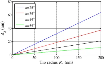
model selection for different scratching depth is based on the value of Δ2, and the Eq. (3) shows the value of Δ2 is
related with the face angle and the tip radius, the corresponding relationship is shown in Fig. 3, indicating a larger
[image:6.595.212.397.461.574.2]face angle and tip radius leads to a larger value of Δ2.
Fig. 3. Values of Δ2 with different tip radius and face angle
2.2. The horizontal projected area of tip-sample interface
0 50 100 150 200
0 20 40 60 80
Tip radius R0 (nm)
2
(
nm
)
=25o
=35o
=45o
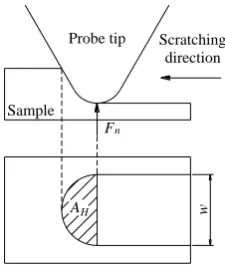
Fig. 4 the schematic of probe tip based scratching
As shown in Fig. 4, for general probe tip, it has been widely accepted that the normal force Fn is the product of
the flow stress ζp of the sample material and the horizontal projected area AHof the tip-sample interface [8-12], as
described in Eq. (4), where the area AH is a function of the scratching depth h.
n p HF
A
h
(4)In the scratching of the spherical capped conical tip model, only the spherical cap surface of the tip model
contacts with the sample, the horizontal projected area of the tip-sample interface can be easily obtained as
2
2
2
H
w
A
(5)where w is the width of nanochannel and defined by 2
20 0
2
w
R
R
h
.In the scratching of the spherical capped regular three side pyramidal tip model, the cutting surface is different
in the four scratching directions due to the pyramid geometric characteristics, and thus leading to different
tip-sample interface. As a result, it is necessary to consider the scratching direction in the calculation of the
horizontal projected area of the tip-sample interface, and four mutually perpendicular scratching directions
expressed by d1-d4 are defined as shown in Fig. 5.
Probe tip
AH
Fn
Scratching direction
Sample
w
x y z
d1 d2
d4
[image:7.595.252.365.75.209.2]d3
The horizontal projected areas of the tip-sample interface of the regular three side pyramid tip model
scratching in four directions are shown in Fig. 6, where the red dotted line is the scratched groove, the shaded area
is the horizontal projected area of the tip-sample interface. In the scratching direction d1, two pyramid surfaces
contact with the sample, and they are symmetric about the cutting blade, the corresponding horizontal projected
areas AHd1 of the tip-sample interface and the scratching width wd1 are shown in Fig. 6(a). In the scratching
direction d2, as shown in Fig. 6(b), only one pyramid surface contacts with the sample and so the area AHd2 is half
of AHd1, but the scratching width is equal.
2 21
2 3
tan
Hd
A
AF
h
(6)2 1
/ 2
Hd Hd
A
A
(7)
1 2
2
tan
d d
w
w
AF
h
(8)
(a) (b)
[image:8.595.148.495.247.643.2]
(c) (d)
Fig. 6. Horizontal projected areas of the tip-sample interface of the regular three side pyramid tip model scratching in the four
directions.
In the scratching directions d3 and d4, the scratching process is same, two pyramid surfaces contact with the
sample, but they are not symmetric about the cutting blade. According to Figs. 6(c) and (d), the horizontal projected
area of tip-sample interface is equal to that in the scratching direction d1, but the scratching width is decided by
Dd1
Bd1
Cd1 Ad1
wd
1
Dd2
Bd2
Cd2 Ad2 wd2
Dd3
Bd3
Cd3 Ad3
wd3
Dd4
Bd4
Cd4 Ad4
wd4
d1 d2
both the face angle and edge angle.
3 4 1
Hd Hd Hd
A
A
A
(9)
3 4
tan
tan
d d
w
w
AF
h
(10)3. SPH simulation model
3.1. SPH method
SPH is a mesh-less method based on Lagrangian method, the sample is discretized with a set of SPH particles,
which include the material properties and state variables. Compared with the traditional finite element analysis,
SPH method can easily deal with large distortions, because the chips can naturally separate from the sample. This
kind of method has been successfully applied in the micro cutting [27-29].
3.2. Simulation model
Both spherical capped conical tip model and spherical capped regular three side pyramid model are seen as
rigid in the simulation, which are constructed and meshed in ANSYS environment firstly, and then they are
imported into the LS-DYNA software to implement the scratching with the SPH sample model. The scratching
depth is from 20nm to 200nm in this paper.
Generally, in order to avoid the effect of the sample boundary on the simulation accuracy, a larger sample
model is needed when the scratching depth is large, and thus if the particle size keeps constant, there will be too
many SPH particles in the simulation of large scratching depth, which will lead to a very long simulation time.
Therefore, the SPH particle diameters are changed based on the scratching depth in this paper. The boundary
dimension of the sample should be large enough that the boundaries do not generate stress during the scratching,
which may cause uncertainty to the simulation results, so the sample dimension changes based on the scratching
depth and direction, a larger scratching depth needs a larger sample model. In the sample modeling, the particle
number is reduced or keeps invariable, but the boundary dimension is increased due to the increase of SPH particle
diameter. After many attempts, the diameter and the number of SPH particle for different scratching depth are listed
in Table 1.
The sketch of the scratching model is shown in Fig. 7. The bottom surface of the sample is fixed in the whole
six degrees of freedom, the translational motion of the front and back boundary surfaces along the scratching
direction are constrained, and the translational motion of bilateral boundary surfaces are constrained in the
and the spherical capped regular three side pyramidal tip are shown in Figs. 8 (a) and (b), respectively.
Table 1 SPH particle diameter in different scratching depth
Sample model for spherical capped
conical tip scratching
Sample model for spherical capped regular three side
pyramidal tip scratching
Scratching depth (nm) 20 40 60 80 120 160 200
SPH particle diameter (nm) 7 14 20 20 30 40 50
SPH particle number
(scratching direction × lateral
direction × z direction)
90×90×30 90×60×30 75×50×25 75×50×25 75×50×25 60×50×25 60×50×25
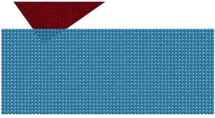
(a) SPH simulation model of spherical capped conical tip
[image:10.595.57.536.133.422.2](b) SPH simulation model of spherical capped regular three side pyramidal tip
Fig. 8. The SPH simulation model Sample
Probe
Scratching direction
z
Fig. 7. Sketch of the scratching model
Front boundary surface
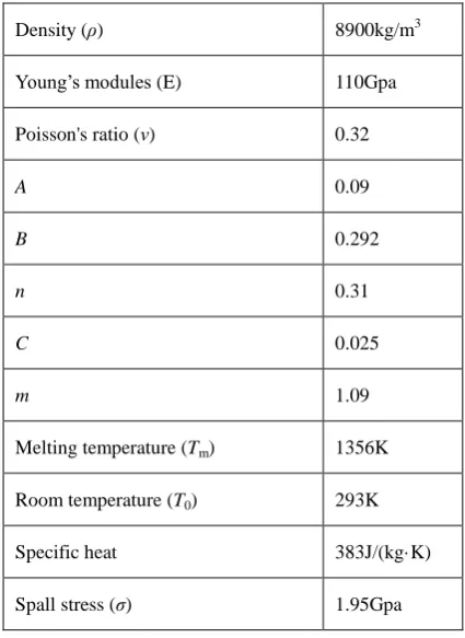
[image:10.595.202.412.595.710.2]The probe tip is seen as rigid with density 3520kg/m3, young's modules 1100Gpa and poison's ratio 0.29. The
Oxygen-Free High-Conductivity (OFHC) cooper is selected as sample and described by Johson-Cook model [30],
which has been widely used in engineering for the simple form and few parameters. It can be expressed in the
following form.
00 0
1
ln
1
m n
m
T
T
A B
C
T
T
(11)where ζ is the equivalent stress, ε is the equivalent plastic strain,
and
0are the current and reference strain ratesrespectively, Tm is the melting temperature, T is the experimental temperature, and T0 is the room temperature. A B
n C and m are unknown parameters, which can be obtained from the experimental testing, and the corresponding
[image:11.595.191.404.336.628.2]values used in this paper are listed in Table 2 [27, 28, 31].
Table 2 Parameters of the Johson-Cook model of OFHC cooper
Density (ρ) 8900kg/m3
Young’s modules (E) 110Gpa
Poisson's ratio (ν) 0.32
A 0.09
B 0.292
n 0.31
C 0.025
m 1.09
Melting temperature (Tm) 1356K
Room temperature (T0) 293K
Specific heat 383J/(kg·K)
Spall stress (ζ) 1.95Gpa
4. Simulation and discussion
4.1. The effect of scratching speed
Considering the wide applications of spherical capped conical tip model, this model is selected for the analysis
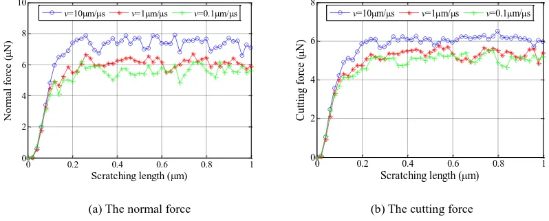
of the effect of scratching speed on the scratching process. Three scratching speeds of 10μm/μs, 1μm/μs and
0.1μm/μs are simulated under a scratching depth 60nm on the same sample model. The simulation results including
than the actual scratching speed, the approximate trend is acceptable. According to the simulation results, both the
normal force and cutting force increase a little with the increase of the scratching speed, the reasonable explanation
is that the generated chips cannot flow away in time in high scratching speed, leading to the area increase of
tip-sample interface. It is noted the increase of the normal force is very limited, therefore, in order to save
simulation time the scratching speed in following simulation adopts 10μm/μs.
The friction coefficient is another effective parameter to assess the scratching process, which is defined as the
ratio of the cutting force and the normal force [19, 32]. According to Fig. 9 (a) and (b), the friction coefficient with
scratching speed 10μm/μs, 1μm/μs and 0.1μm/μs in stable scratching state is 0.82, 0.87 and 0.91, respectively. The
friction coefficient is reduced with the increase of the scratching speed, the possible reason is the probe tip with
faster scratching speed has larger kinetic energy, the generated chips are easier to crack in front of the tip, so the
cutting force increases less than the normal force.
[image:12.595.104.503.345.506.2](a) The normal force (b) The cutting force
Fig. 9. The normal force and lateral force of spherical capped conical tip model with different scratching speed
4.2. The effect of scratching depth and scratching direction
According to the analyses in section 2, the spherical capped conical tip model is used in the scratching depth
smaller than 60nm, and the spherical capped regular three side pyramidal tip model is used in the scratching depth
larger than 60nm. Three scratching depths of 20nm, 40nm and 60nm are selected for the spherical capped conical
tip model scratching simulation. In order to save the simulation time, the scratching length is 0.3μm in depth of
20nm, and 1μm in depth of 40nm and 60nm. The normal forces generated during the scratching with the three
scratching depths are shown in Fig. 10.
The spherical capped regular three side pyramidal tip model with α=35o are firstly selected for the scratching
simulation. According to Eq. 3, the value of Δ2 is about 16nm, based on the analysis in section 2, the area function
of three side pyramid tip model is more applicable when the scratching depth is far larger then Δ2, so the scratching
0 0.2 0.4 0.6 0.8 1
0 2 4 6 8 10
Scratching length (m)
N or m a l for c e ( N)
v=10m/s v=1m/s v=0.1m/s
0 0.2 0.4 0.6 0.8 1
0 2 4 6 8
Scratching length (m)
C ut ti ng for c e ( N)
depths of 80nm, 120nm, 160nm and 200nm are selected. The normal force of the spherical capped regular three
side pyramidal tip model is related with the scratching direction, so the simulations are processed in all four
directions, the generated normal forces in different scratching depth are shown in Fig. 11, and the scratched grooves
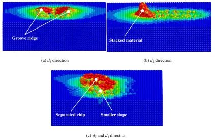
[image:13.595.206.389.168.289.2]in scratching depth of 160nm are shown in Fig. 12.
Fig. 10. The normal force of spherical capped conical tip model with different scratching depth
(a) d1 direction (b) d2 direction
(c) d3 and d4 direction
Fig. 11. The normal force of spherical capped regular three side pyramidal tip model with different scratching depth.
0 0.06 0.12 0.18 0.24 0.3 0 2 4 6 8 10
Scratching length (m)
N or m a l for c e ( N)
h=20nm h=40nm h=60nm 0 0.2 0.4 0.6 0.8 1
0 0.2 0.4 0.6 0.8 1
0 10 20 30 40 50 60 70
Scratching length (m)
N or m a l for c e ( N) h=80nm h=120nm h=160nm h=200nm
0 0.1 0.2 0.3 0.4 0.5 0.6 0.7 0.8 0.9 1 0 10 20 30 40 50
Scratching length (m)
N or m a l for c e ( N) h=80nm h=120nm h=160nm h=200nm
0 0.1 0.2 0.3 0.4 0.5 0.6 0.7 0.8 0.9 1 0 10 20 30 40 50
Scratching length (m)
[image:13.595.75.514.317.655.2](a) d1 direction (b) d2 direction
[image:14.595.88.512.75.348.2](c) d3 and d4 direction
Fig. 12. The chips generated by spherical capped regular three side pyramidal tip model in different direction
In both Figs. 10 and 11, the normal forces increase with the increase of scratching depth and reach a steady
value after a period of time, which means the scratching goes into steady state. The larger of the scratching depth,
the slower to the steady scratching state, this is because more materials deform in the large scratching depth, which
need more time to transfer the deformation. Comparing the normal force of Figs. 11(a) and (c), it is noted that the
normal force in the d1 direction is larger than that in the d3 direction, but they should be equal according to the
theoretical analysis. This is because in the d1 direction, most removed material are divided into two sides of the
groove and form ridge due to the cut of front blade of the pyramid, as shown in Fig. 12(a), which leads to the
increase of the tip-sample interface in some degree, and further a larger normal force; while in the d3 and d4
directions, the removed material flow to the side of the groove with smaller slope, as shown in Fig. 12(c), the
separated chips are easy to form than that in the d1 direction, although the chips also contact with the probe tip, but
the force will be very small. In the d2 direction, the normal force is extremely larger than half of the normal force in
the d1 and d3 directions, which is because the removed material can only flow away along the front pyramid surface,
resulting in a mess of stack of the material, as shown in Fig. 12(b), this will increase the tip-sample interface
significantly.
Groove ridge Stacked material
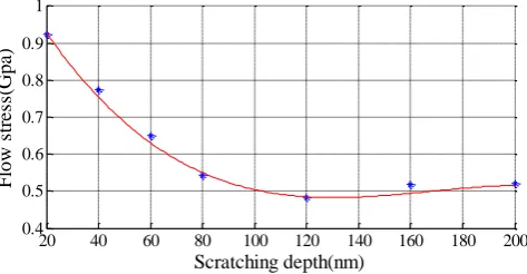
Fig. 13. The flow stress of the sample (OFHC cooper)
Based on the generated normal force of the spherical capped conical tip and spherical capped regular three
side pyramidal tip in the d3 and d4 directions, the flow stress of the sample is obtained in scratching depth from
20nm to 200nm, which is shown in Fig. 13. This indicates that the flow stress is high in small depth, and then
reduces to a steady value of 0.5Gpa with the increase of the scratching depth. A cubic function is used to fit the
discrete flow stress point, and it can be expressed by following equation.
7 3 5 2 2
1.65 10
8.29 10
1.32 10
1.16
stress
h
h
h
(12)Based on Eq. (12), the comparison of the theoretical and simulation normal force is shown in Fig. 14. In the
scratching depth from 20nm to 60nm, the normal forces agree very well for the spherical capped conical tip model.
In the scratching depth from 80nm to 200nm, the compliance degree depends on the scratching direction. Due to
the groove ridge in the d1 direction and the material stack in the d2 direction, the simulated normal force is
relatively larger than that of the theoretical calculation, the error is about 25% in the d1 direction, but in the d2
direction the simulated force is almost twice of that of the theoretical force. In thed3 direction, the simulated normal
forces are in agreement with those of the theoretical calculation.
(a) d1 direction (b) d2 direction
20 40 60 80 100 120 140 160 180 200 0.4 0.5 0.6 0.7 0.8 0.9 1 Scratching depth(nm) F low s tr e ss (G pa )
20 40 60 80 100 120 140 160 180 200
0 10 20 30 40 50 60 Scratching depth(nm) N or m a l for c e ( N) simulation force theoretical force
20 40 60 80 100 120 140 160 180 200
(c) d3 direction
Fig. 14. The comparison of the normal force in simulation and theoretical calculation in different scratching direction
4.3. The effect of the face angle
In the spherical capped regular three side pyramidal tip scratching, the face angle has significant influence on
the tip-sample interface area, and thus a series of simulation with different face angle (25˚, 35˚, 45˚, 55˚) are
conducted in this paper. According to previous analyses, the simulated normal force in the d3 and d4 directions are
in good agreement with those of the theoretical calculation, so the simulation is performed in the d3 direction with
scratching depth 160nm. The simulation results of the generated chips and the von mises stress are shown in Fig. 15,
which indicates the separated chips are formed in small face angle of 25˚ and 35˚, but when the face angle reaches
up to 45˚or larger, the separated chips cannot break away from the sample and even be replaced by ridge on left
side of the groove, where the slope is smaller than that on the right side. Moreover, the pyramidal model with
bigger face angle results in larger groove width and residual stress area during the scratching. These phenomena are
explained as follows.
According to Fig. 6(c) and (d), one of the two contacted surface in the d3 direction is parallel with the
scratching direction, the other is called the material flow surface, where the chips flow away from this surface.
Considering the cutting blade and the material flow surface are in three dimensional space relative to the scratching
direction, the material flow direction is divided in horizontal plane and C-C plane as shown in Fig. 16. In the
horizontal plane, the material flow along the edge of the probe cross section, the flow angle is 60° relative to the
scratching direction, which is same for all regular three side pyramidal probe tip; In the C-C plane, the flow
direction is upward along the material flow surface and the flow angle is approximately equal to the face angle α.
Thus, with the increase of the face angle, the material flow direction in C-C plane becomes more parallel to the
horizontal plane, the material flow space between the material flow surface and the sample surface becomes smaller,
which slow down the material flow speed and make the removed material difficult to separate from the sample,
leading to the phenomenon of groove ridge and larger residual stress area.
20 40 60 80 100 120 140 160 180 200 0
10 20 30 40 50
Scratching depth(nm)
N
or
m
a
l
for
c
e
(
N)
The simulated normal forces during the scratching are compared with the theoretical normal forces, and the
results are shown in Fig. 17. It is noted that the normal forces are in good agreement in small face angles of 25˚ and
35˚, but the errors reach up to 36.5% and 47.5% in face angles of 45˚ and 55˚, respectively. This is because the
removed material flow away in small face angles of the 25˚ and 35˚, but form the groove ridge in larger face angle
of 45˚ and 55˚, and the phenomenon has increased trend with the increase of face angle, the groove ridge usually
leads to a larger tip-sample contact area and normal force, further a larger error.
(a) Face angle of 25˚ (b) Face angle of 35˚
[image:17.595.197.417.566.722.2]
(c) Face angle of 45˚ (d) Face angle of 55˚
Fig. 15. The scratching process of spherical capped regular three side pyramidal tip model with different face angle
Sample
Cutting blade
Material flow surface C
C Material flow direction
in horizontal plane
Scratching direction
(a) In horizontal plane
Separated chip Separated chip
α β
Material flow direction in C-C plane
Sample
[image:18.595.195.427.78.196.2](b) In C-C plane
Fig. 16. The material flow direction
Fig. 17. The normal force of the spherical capped regular three side pyramidal tip model with different face angle
5. Conclusions
A spherical capped conical tip model and a spherical capped regular three side pyramidal tip model are
introduced for the common three side probe tip. The former is used in the small scratching depth from 20nm to
60nm and the latter is used in the larger scratching depth from 80nm to 200nm. The horizontal projected areas of
the tip-sample interface of these two models during the scratching are theoretically analyzed for the calculation of
the normal force. In the scratching simulation, the probe tips are seen as rigid, and the sample is constructed with
Johnson-Cook model. The SPH method is adopted for the simulation in LS-DYNA software.
According to the simulation results, a higher scratching speed leads to a larger normal force and cutting force,
but the increase is limited, the normal force increases with the increase of scratching depth in both models. In the
scratching simulation of spherical capped regular three side pyramidal tip model, the scratching process is different
in different directions. In the d1 direction, due to the cut of front blade of the pyramid model, most of the removed
materials are divided to two sides of groove and form ridge; in the d2 direction, a lot of removed materials stack in
the front pyramid surface; in the d3 and d4 directions, the removed materials flow to the side with smaller slope of
the groove, and it is easier to form separated chips than in d1 direction. In conclusion, the normal forces scratched
in the d3 and d4 direction are closest to the theoretical calculation. Furthermore, the increase of face angle leads to
25 30 35 40 45 50 55
0 50 100 150 200
Face angle (o)
N
or
m
a
l
for
c
e
(
N)
[image:18.595.188.396.254.376.2]the increase of the normal force and the residual stress area, and the error between the theoretical and simulated
normal forces is also getting large when the face angle is bigger than 35˚.
Acknowledgements
This research is supported by National Natural Science Foundation of China (Nos. 51275337, 51205279,
51405333, 51420105007) and EU H2020 FabSurfWAR (No. 644971).
References
[1] J. L. Perry, S. G. Satish, "Review of fabrication of nanochannels for single phase liquid flow", Microfluidics
and Nanofluidics, vol. 2, no. 3, pp. 185–193, 2006.
[2] Y. Yan, T. Sun, Y. Liang, S. Dong, "Investigation on AFM-based micro/nano-CNC machining system",
International Journal of Machine Tools & Manufacture, vol. 47, pp.1651–1659, 2007.
[3] B. A. Gozen, O. B. Ozdoganlar, "Design and evaluation of a mechanical nano manufacturing system for nano
milling", Precision Engineering, vol.36, pp. 19-30, 2012.
[4] K. Bourne, S. G. Kapoor, R. E. DeVor, "Study of a High Performance AFM Probe-Based Microscribing
Process", Journal of Manufacturing Science and Engineering, Vol. 132, p. 030906, 2010.
[5] W. P. Jeong, C. C. Soo, C. Hyun, "Portable nano probe for micro/nano mechanical scratching and measuring",
Transaction of Nonferrous Metals Society of China, vol. 21, pp. s205-s209, 2011.
[6] Y. Geng, Y. Yan, X. Zhao, "Fabrication of millimeter scale nanochannels using the AFM tip-based
nanomachining method", Applied Surface Science, vol. 266, pp. 386-394, 2013.
[7] G. Gu, L. Zhu, C. Su, H. Ding and S. Fatikow, “Modeling and control of piezo-actuated nanopositioning
stages: A survey,” IEEE Transactions on Automation Science and Engineering, vol. 13, no. 1, pp. 313-332,
2016.
[8] Z. Lin, Y. Hsu, “A study of estimating cutting depth for multi-pass nanoscale cutting by using atomic force
microscopy”, Wear, vol. 258, pp. 4513-1522, 2012.
[9] Z. Wang, N. Jiao, S. Tung, Z. Dong, “Research on the atomic force microscopy-based fabrication of
nanochannels on silicon oxide surfaces”, Chinese science bulletin, vol. 55, no. 30, pp. 3466-3471, 2010.
[10] Z. Wang, N. Jiao, S. Tung, Z. Dong, “Atomic force microscopy-based repeated machining theory for
nanochannels on silicon oxide surfaces”, Applied Surface Science, vol. 257, pp. 3627-3631, 2011.
Wear, vol. 278, pp. 71-76, 2012.
[12] Y. Geng, Y. Yan, Y. Xing, "Modelling and experimental study of machined depth in AFM-based milling of
nanochannels", International Journal of Machine Tools & Manufacture, vol. 73, pp. 87–96, 2013.
[13] Y. Geng, Y. Yan, Y. Xing, Q. Zhang, X. Zhao, and Z. Hu, “Effect of cantilever deformation and tip-sample
contact area on AFM nanoscratching”, Journal of vacuum science & technology B, vol. 31, p. 061802, 2013.
[14] B. Meng, F. Zhang, Z. Li, “Deformation and removal characteristics in nanoscratching of 6H-SiC with
Berkovich indenter”, Materials Science in Semiconductor Processing, vol. 31, pp. 160-165, 2015.
[15] C. Pan, T. Wu, C. Liu, et al, “Study of scratching Mg-based BMG using nanoindenter with Berkovich probe”,
Materials Science and Engineering A, vol. 527, pp. 2342-2349, 2010.
[16] B. Meng, Y. Zhang, F. Zhang, "Material removal mechanism of 6H-SiC studied by nano-scratching with
Berkovich indenter", Applied Physics A, vol. 122, p. 247, 2016.
[17] P. Zhu, Y. Hu, T. Ma, H. Wang, "Study of AFM-based nanometric cutting process using molecular dynamics",
Applied Surface Science, vol. 256, pp. 7160–7165, 2010.
[18] Q. Pei, C. Lu, H. Lee, "Large scale molecular dynamics study of nanometric machining of copper",
Computational Materials Science, vol. 41, pp. 177–185, 2007.
[19] J. Zhang, T. Sun, Y. Yan, Y. Liang, “Molecular dynamics study of scratching velocity dependency in
AFM-based nanometric scratching process”, Materials Science and Engineering A, vol. 505, pp. 65-69, 2009.
[20] J. Zhang, T. Sun, Y. Yan, et al, “Molecular dynamics simulation of subsurface deformed layers in AFM-based
nanometric cutting process”, Applied Surface Science, vol. 254, pp. 4774-4779, 2008.
[21] Y. Yan, T. Sun, S. Dong, Y. Liang, “Study on effects of the feed on AFM-based nano-scratching process
using MD simulation”, Computational Materials Science, vol. 40, pp. 1-5, 2007.
[22] P. Zhang, H. Zhao, C. Shi, et al, "Influence of double-tip scratch and single-tip scratch on nano-scratching
process via molecular dynamics simulation", Applied Surface Science, vol. 280, pp. 751-756, 2013.
[23] T. Fang, C. Liu, S. Shen, et al, "Nanoscratch behavior of multi-layered films using molecular dynamics",
Applied Physics A, vol. 90, pp. 753-758, 2008.
[24] R. Gingold and J. Monaghan, "Smoothed particle hydrodynamics: theory and application to non-spherical
stars," Monthly Notices of the Royal Astronomical Society, vol. 181, pp. 375-89, 1977.
[25] A. Vázquez-Quesada, M. Ellero, "Rheology and microstructure of non-colloidal suspensions under
shearstudied with Smoothed Particle Hydrodynamics", Journal of Non-Newtonian Fluid Mechanics, vol. 233,
[26] W. Li, S, Yin, X. Wang, Numerical investigations of the effect of oblique impact on particle deformation in
cold spraying by the SPH method, Applied Surface Science, vol. 256, pp. 3725-3734, 2010.
[27] H. Zhao, P. Zhang, H. Liu, "Influences of residual stress induced by cutting on subsequent scratch using
smooth particle hydrodynamic (SPH)", Materials Transactions, vol. 55, pp. 1440-1444, 2014.
[28] H. Zhao, C. Liu, T. Cui, et al, "Influences of sequential cuts on micro-cutting process studied by smooth
particle hydrodynamic", Applied Surface Science, vol. 284, pp. 366-371, 2013.
[29] J. Cao, Y. Wu, J. Li, Q. Zhang, "Study on the material removal process in ultrasonic-assisted grinding of SiC
ceramics using smooth particle hydrodynamic (SPH) method", International Journal of Advanced
Manufacturing Technology, vol. 83, pp. 985-994, 2016.
[30] G. R. Johnson, W. H. Cook, "A constructive model and data for metals subjected to large strains, high strain
rates and high temperatures", in: Proceedings of the Seventh International Symposium on Ballistics, pp.
541-547. 1983.
[31] L. Campagne, L. Daridon and S. Ahzi, "A physically based model for dynamic failure in ductile metals",
Mechanics of Materials, vol. 37, pp. 869-886, 2005.
[32] M. Malekian, S. Park, D. Strathearn1, M. G. Mostofa1 and M. Jun, "Atomic force microscope probe-based