ISSN Online: 2327-4379 ISSN Print: 2327-4352
DOI: 10.4236/jamp.2018.69163 Sep. 28, 2018 1916 Journal of Applied Mathematics and Physics
Discrete Time-Frequency Signal Analysis and
Processing Techniques for Non-Stationary
Signals
S. Sivakumar
1, D. Nedumaran
21P.G. and Research Department of Electronics, Government Arts College, Paramakudi, Tamilnadu, India 2Central Instrumentation and Service Laboratory, University of Madras, Guindy Campus, Chennai, India
Abstract
This paper presents the methodology, properties and processing of the time-frequency techniques for non-stationary signals, which are frequently used in biomedical, communication and image processing fields. Two classes of time-frequency analysis techniques are chosen for this study. One is short-time Fourier Transform (STFT) technique from linear time-frequency analysis and the other is the Wigner-Ville Distribution (WVD) from Qua-dratic time-frequency analysis technique. Algorithms for both these tech-niques are developed and implemented on non-stationary signals for spec-trum analysis. The results of this study revealed that the WVD and its classes are most suitable for time-frequency analysis.
Keywords
Non-Stationary Signal, Short Term Fourier Transform, Wigner Ville Distribution, Algorithm
1. Introduction
In nature, most of the signals are non-stationary and time-varying signals. Fur-ther, the classical and modern methods are widely used to process the stationary signals in which they transform the signals from time-domain to frequen-cy-domain and vice versa. The stationary signals do not change in their statistic-al properties over the length of the anstatistic-alysis time. Many signstatistic-als of biologicstatistic-al ori-gin are varying in a random manner called non-stationary signals and are changing their properties over the length of the analysis time. The basic idea of time-frequency analysis is to design a joint function, which can describe the
How to cite this paper: Sivakumar, S. and Nedumaran, D. (2018) Discrete Time- Frequency Signal Analysis and Processing Techniques for Non-Stationary Signals. Journal of Applied Mathematics and Phys-ics, 6, 1916-1927.
https://doi.org/10.4236/jamp.2018.69163
Received: June 15, 2018 Accepted: September 25, 2018 Published: September 28, 2018
Copyright © 2018 by authors and Scientific Research Publishing Inc. This work is licensed under the Creative Commons Attribution International License (CC BY 4.0).
DOI: 10.4236/jamp.2018.69163 1917 Journal of Applied Mathematics and Physics characteristics of signals on a time-frequency plan. Time-frequency transforms map a one-dimensional function of time x(t)into a two-dimensional function of time and frequency x(t, f) [1].
In order to process such non-stationary signals, time-frequency analysis and processing methods are required. Generally, they fall into one of the two catego-ries of time-frequency distributions (TFDs), the linear time-frequency distribu-tions and the quadratic time-frequency distribudistribu-tions (QTFDs). The TFDs give useful information about frequency changes over time. The signal component could be considered as energy continuity in time without abrupt changes in fre-quency [2].
Non-stationary signals comprise of mono component or multi-component. Linear TFDs, such as short-time Fourier transform (STFT), which is often used as a first choice of tool in time-frequency analysis, due to their simplicity in usage, well-established algorithm and analysis technique [3]. In order to get en-hanced time-frequency resolution QTFDs have been introduced. QTFD classes are non-linear methods in which Wigner-Ville Distribution (WVD) is the pri-mary distributions of QTFD class, from which so many classes called Cohen’s TFDs, have been introduced for various non-stationary signal-processing appli-cations. Consequently, studies on the TFRs have been applied to analyze, modify and synthesize non-stationary signals or time-varying signals. In this paper, two types of time-frequency representation techniques are considered; Linear Time frequency distribution and quadratic time frequency distribution and their prin-ciple properties are investigated. The realization of this distribution for hardware and software platforms requires a discrete version. As a result, algorithms were developed for discrete time-frequency STFT and WVD techniques and were tested on non-stationary signals for joint time-frequency analysis.
2. Short-Time Fourier Transformation
STFT is one of the linear time-frequency representations based on the straightforward approach of slicing the waveform of interest into a number of short segments and performing the analysis on each of these segments, using standard Fourier transform. A window function is applied to segment the data, which effectively isolates the segment from the overall signal data, since the segment within the window is assumed as stationary and provides time localiza-tion. Then, Fourier Transform is applied to the windowed data and the spectrum or spectrogram could be calculated from the estimated Fourier coefficients.
The STFT of the signal x(t) is given by [4]
( )
2( ) (
)
2π 2, t e j f d
t
X t f τ x w t τ
τ τ τ τ
+ −
−
=
∫
− (1)where w t
(
−τ
)
is a window function andτ
is the variable that slides the window across the signal, x(t).The discrete version of STFT of the signal x(n) is given by
(
,)
N1( ) (
)
e j kn N nX m k x n w n k −ω
=
DOI: 10.4236/jamp.2018.69163 1918 Journal of Applied Mathematics and Physics where n is the time index, k is the frequency index and w n k
(
−)
is the analysiswindow that selectively determines the portion of x(n) for analysis. X(m, k) can be expressed as convolution of the signal x n
( )
e−j kn Nω with the windowfunc-tion w n k
(
−)
. The spectrogram is the square of the magnitude of the STFTob-tained in (2)
(
)
(
)
2, ,
PSD tω = X m k (3)
Upon selection of discrete STFT, the next step is to select an appropriate win-dow and its size where two closest sinusoids can be distinguished using Equation (3). However, non-stationary signals may involve a large number of sinusoids in close proximity. This results in a very small Δf and consequently a large window is required. This makes the STFT very similar to the Fourier transform and will hamper temporal resolution. In order to select an appropriate window size a novel empirical model is proposed in [5][6], which adaptively selects a window size and is given by
3B fs s
W
µ
= (4)
where fs is the sampling frequency and μ = 386.3 for ∆ =f µ3. For rectangular
window, Bs = 2, Hanning/Hamming window Bs= 4 and for Blackman window Bs
= 6.
3. Wigner and Wigner-Ville Distributions
All Quadratic Time-Frequency representations should satisfy the time and fre-quency shift invariance belong to general class of distributions introduced by Cohen and are given by the following expression [7]
( )
, 1 e e e( )
, * d d d2π 2 2
j t j j u
w t f = −θ −τω −θ ∅
θ τ
x u +τ
x u−τ
uτ θ
∫∫∫
(5)where x(u) is the time signal, x*(u) is its complex conjugate and ∅
( )
θ τ
, is an arbitrary function called the kernel. By choosing different kernels, different dis-tributions are obtained. Wigner distribution is obtained by taking ∅( )
θ τ
, =1. Here, the range of all integrations is from −∞ to ∞.A real valued signal x(t) is used in WDF, which has positive and negative fre-quency components and introduced aliasing or cross-terms between positive and negative frequencies in time-frequency domain.
Wigner-Ville Distribution
DOI: 10.4236/jamp.2018.69163 1919 Journal of Applied Mathematics and Physics analytic signal may be expressed by, [8][9],
( ) ( )
( )
z t =x t + jH x t (6)
where H[x(t)] is the Hilbert transform, which is generated by the convolution of the impulse response h(t) of 90˚ phase shift as follows
( )
( ) ( )
H x t =x t h t∗ (7)
( )
2 sin π
2
2 , 0
π
0, 0
t
h t t
t t = ≠ =
The discrete form of the equation is given by,
( )
k(
) ( )
H x n ∞ h n k x k
=−∞
= −
∑
(8)Substituting the kernel ∅
( )
θ τ
, =1 in Equation (5), the continuous time WVD is obtained for continuous time signal( )
, * e 2π d2 2
j f
Wx t f ∞ z t
τ
z tτ
− ττ
−∞
= + −
∫
(9)where t is time domain variable, f is frequency domain variable and z(t) is ana-lytical associate of the real signal x(t) obtained from Hilbert Transform. The Wigner-Ville Distribution (WVD) is the most powerful and fundamental time frequency representation [10]. The superior properties of the WVD over the STFT technique make it ideal for signal processing in such diverse fields as radar, sonar, speech, seismic and biomedical analysis [11][12]. For these applications, there is a need of a flexible Wigner-Ville Distribution for non-stationary signal analysis.
The Discrete version of WVD of the signal x(n) is given by [13][14].
(
,)
2 e 2πNmn(
) (
*)
k
W n m =
∑
∞=−∞ − z n k z n k+ − (10)(
,)
e 2πNnm( )
,( )
,xx k xx
m
w n m ∞ − R n k FFT R n k
=−∞
=
∑
= (11)where t = nTs and f = m/(NTs).
The WVD uses a variation of autocorrelation, where time remains in the re-sult. This is achieved by comparing the waveform with itself for all possible lags, i.e., the comparison is done for all possible values of time. This comparison gives rise to the defining equation called instantaneous auto-correlation function for continuous time signal
( )
, *2 2
xx
R t
τ
=z t +τ
z t−τ
(12)
Its discrete version is
(
,)
(
) (
*)
xx
R n k =z k n z k n+ − (13)
DOI: 10.4236/jamp.2018.69163 1920 Journal of Applied Mathematics and Physics retains both lag and time. Some important properties examined shows that WVD is always real and satisfies time and frequency marginal characteristics.
4. STFT Algorithm Implementation
Fast Fourier Transform (FFT) is applied using straight forward approach using the separate function [B,t,f] coded in MATLAB. Here, B is a complex matrix containing the magnitude and phase of the STFT frequency spectrum with the rows encoding the time-axis and the column representing the frequency-axis and t and f are optional argument vectors that can be helpful in plotting.
5. DWVD Algorithm Implementation
The following are the steps involved to develop the algorithm:
Step 1: Convert the real signal into analytical signal using Hilbert transform. Step 2: Compute the WVD using a separate function. The input function has arguments x and fs.
Step 3: Compute the instantaneous autocorrelation using loop to construct an array.
Step 4: Find the WVD magnitude using FFT.
6. Spectrum Analysis of the Proposed Time-Frequency
Distributions
1) Two Sequential Sinusoid
The proposed STFT and WVD techniques are tested over different inputs such as a two sequential sinusoid of 10 Hz and 50 Hz. The sinusoid is preceded and followed by a time gap of 0.5 sec. The simulated signals are shown in Figure 1.
The STFT magnitude spectrum and contour plot shown in Figure 2 and Fig-ure 3 produces a time-frequency plot with the step change in frequency ap-proximately at the correct time, but the step change of time and frequency are not defined very preciously.
The lack of finite support in either time or frequency is evident from the ap-pearance of energy slightly before 0.5 sec and after 0.5 sec and energy other than 10 and 50 Hz as shown in Figure 3. Further, when the window length is in-creased, the frequency resolution increases but there is a decreases in the time resolution.
DOI: 10.4236/jamp.2018.69163 1921 Journal of Applied Mathematics and Physics Figure 1. Two sequential sinusoids of 10 Hz and 50 Hz with a time gap of 0.5 sec.
Figure 2. Magnitude spectrum of two sinusoids using STFT.
Figure 3. Contour plot of two sinusoids using STFT.
kernel function ∅
( )
θ τ
, =1, which introduces the cross term due to instanta-neous autocorrelation.2) Chirp Signal
[image:6.595.205.541.469.618.2]DOI: 10.4236/jamp.2018.69163 1922 Journal of Applied Mathematics and Physics Figure 4. Magnitude spectrum of two sinusoids using DWVD.
Figure 5. Contour plot of two sinusoids using DWVD.
linearly increasing term. A linearly increasing sine wave that varies between 10 and 200 Hz over a 1 sec period is generated as shown in Figure 6.
The STFT magnitude spectrum and contour plots shown in Figure 7 and Figure 8 respectively exhibit a time-frequency plot with the step change in fre-quency approximately at the correct time. Further, it shows the chirp signal is linear FM signal, which lead to the appearance of the step changes preciously both in time and frequency axes with no lag in the finite support. Similar to STFT, if there is an increase in window length; DWVD also increases the fre-quency resolution and decreases the time resolution.
In the DWVD magnitude spectrum and contour plots shown in Figure 9 and Figure 10 respectively, the DWVD produces a time-frequency plot with the step change in frequency approximately at the correct time, which shows that the chirp signal is a linear FM signal and so supports the step changes preciously both in time and frequency domains with finite support. The contour plot shows that the signal has low energy. In both the cases the marginal property of the signals are preserved. Hence, STFT and DWVD are suitable to analyse liner non-stationary signals.
3) ECG Signal
DOI: 10.4236/jamp.2018.69163 1923 Journal of Applied Mathematics and Physics Figure 6. Chirp signal.
[image:8.595.208.540.352.524.2]Figure 7. STFT magnitude spectrum of chirp signal.
Figure 8. STFT-contour plot for chirp signal.
Figure 9. DWVD magnitude spectrum of chirp signal.
DOI: 10.4236/jamp.2018.69163 1924 Journal of Applied Mathematics and Physics Figure 10. DWVD-contour plot for chirp signal.
[image:9.595.210.537.606.680.2]Figure 11. Arrhythmia ECG signal with 10 sec time duration.
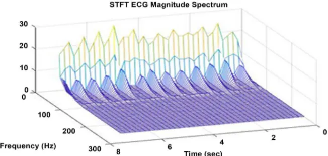
Figure 12. STFT magnitude spectrum with N = 1024, nfft = 128 and overlap = 64 for the Arrhythmia ECG signal with 10 sec time duration.
Table 1. Window parameter for STFT.
Short Time Fourier Transformation
Hanning Window Parameter No of points in the
FFT (N) Window width (nfft) No of overlap (Overlap)
1024 128 64
512 64 32
DOI: 10.4236/jamp.2018.69163 1925 Journal of Applied Mathematics and Physics Figure 13. STFT magnitude spectrum with N = 512, nfft = 64 and overlap = 32 for Arrhythmia ECG signal with 10 sec time duration.
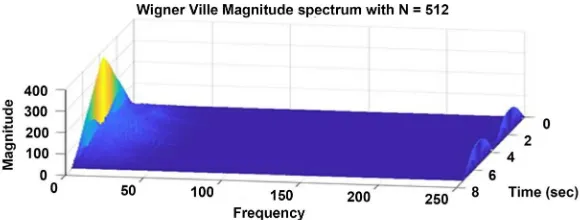
Figure 14. DWVD magnitude spectrum with N = 512 for Arrhythmia ECG sig-nal with 10 sec time duration.
Whereas in DWVD magnitude spectrum shown in Figure 14, the actual sig-nals are found to be in short distances so that local oscillation takes place that introduces cross term between the two auto terms. When it is dominant enough, it could not able to provide good time and frequency resolution. From the above discussion, if the signals are multi component non-linear non-stationary signals, the DWVD is not suitable to analyze the signal until the cross term is eliminated.
7. Conclusion
[image:10.595.228.518.266.376.2]DOI: 10.4236/jamp.2018.69163 1926 Journal of Applied Mathematics and Physics time-frequency structure. In the DWVD, the kernel ∅
( )
θ τ
, =1 introduces cross terms. These cross-terms will be reduced by introducing the window, ker-nel and adaptive filters, which will make the DWVD a more suitable and po-werful tool for non-stationary signal analysis. Since The Wigner Ville distribu-tion preserves all the informadistribu-tion, it will be used for two-dimensional signal processing like digital image processing. This work supports the need of using time-frequency distributions when dealing with non-stationary signals.Conflicts of Interest
The authors declare no conflicts of interest regarding the publication of this pa-per.
References
[1] Hlawatsch, F. and Boudreaux-Bartels, G.F. (1992) Linear and Quadratic Time-Frequency Signal Representations. IEEE Signal Processing Magazine, 9, 21-67.https://doi.org/10.1109/79.127284
[2] Damira, M., Victora, S. and Car Zlatana, B. (2015) Optimizing the Reference Signal in the Cross Wigner-Ville Distribution Based Instantaneous Frequency Estimation Method. Procedia Engineering, 100, 1657-1664.
https://doi.org/10.1016/j.proeng.2015.01.540
[3] Boashash, B., Ed. (2003) Time-Frequency Signal and Processing: A Comprehensive Reference. Elsevier Science, Oxford.
[4] Allen, J.B. (1977) Short Term Spectral Analysis, Modification by Discrete Fourier Transform Synthesis. IEEE Transactions on Acoustics, Speech, and Signal Processing, 25, 235-238. https://doi.org/10.1109/TASSP.1977.1162950
[5] Shibli. N., Khan,O.U. and Tariq, M. (2016) An Efficient Adaptive Window Size Se-lection Method for Improving Spectrogram Visualization. Computational Intelli-gence and Neuroscience, 2016, Article ID: 6172453.
[6] Shin, Y.S. and Jeon, J.-J. (1993) Pseudo Wigner-Ville Time-Frequency Distribution and Its Application to Machinery Condition Monitoring. Shock and Vibration, 1, 65-76.https://doi.org/10.1155/1993/372086
[7] Claasen, T.A.C.M. and Mecklenbräuker, W.F.G. (1980) The Wigner Distribu-tion—A Tool for Time-Frequency Signal Analysis Part Ill: Relations with Other Time-Frequency Signal Transformations. Philips Journal of Research, 35, 372-389. [8] Marple Jr., S.L. (1999) Computing the Discrete-Time ‘Analytic’ Signal via FFT.
IEEE Transactions on Signal Processing, 47, 2600-2603.
https://doi.org/10.1109/78.782222
[9] O’ Toole, J.M., Mesbah, M. and Boashash, B. (2008) A New Discrete Analytic Signal for Reducing Aliasing in the Discrete Wigner-Ville Distribution. IEEE Transactions on Signal Processing, 56, 5427-5434.https://doi.org/10.1109/TSP.2008.929325
[10] Boashash, B. and Black, P.J. (1987) An Efficient Real -Time Implementation of the Wigner-Ville Distribution. IEEE Transactions on Acoustics, Speech and Signal Processing, ASSP-35, 1611-1618.
[11] Debnath, L. (2002) Recent Developments in the Wigner-Ville Distribution and Time-Frequency Signal Analysis. PINSA, 68, 35-36.
DOI: 10.4236/jamp.2018.69163 1927 Journal of Applied Mathematics and Physics
Time-Frequency Techniques for Nonstationary Signals. Journal of Computers, 7, 954-958.https://doi.org/10.4304/jcp.7.4.954-958
[13] O’Toole, J., Mesbah, M. and Boashash, B. (2005) A Discrete Time and Frequency Wigner Ville Distribution Properties and Implementation,
http://eprints.qut.edu.au
[14] Gulum, T.O., Erdogan, A.Y., Durak-Ata, L., Yildirim, T. and Pace, E. (2013) Elliptic Gaussian Filtering for Time-Frequency Signal Analysis. 2013 IEEE Radar Confe-rence, Ottawa, ON, 29 April-3 May 2013, 1-5.
https://doi.org/10.1109/RADAR.2013.6585973
[15] Mousa, A. and Saleem, R. (2010) The Shortage of WVD in Analyzing Abnormal ECG Signal. IEEE Symposium on Industrial Electronics and Applications (ISIEA
2010), Penang, 3-5 October 2010, 651-654.