ISSN Print: 2333-9705
Thermal Performance Analysis of the Battery
Thermal Management Using Phase Change
Material
Limin Song
College of Automotive Engineering, Shanghai University of Engineering Science, Shanghai, China
Abstract
In this paper, the phase change material passive thermal management system for the lithium ion battery module is established, in which the mock-up bat-tery is used to replace the real batbat-tery for the simulation. The temperature rise characteristics of the battery and the melting process of the phase change material in the passive thermal management system are determined through the numerical simulation. The effect of the filling amount of the phase change material on battery thermal performance is also analyzed.
Subject Areas
Electric Engineering, Thermodynamics
Keywords
Phase Change Material, Numerical Analysis, Battery Thermal Management, Battery Spacing
1. Introduction
Lithiumion batteries are widely used in electric vehicles due to their high energy density and long cycle life [1]. The lithiumion batteries generate large amount of heat during charging and discharging because of the internal electrochemical exothermic reaction and joule thermal effect. If the heat cannot be dissipated in time, the accumulation of the heat will lead to the rise of the battery tempera-ture. The overhigh temperature will cause the decline of the cycle performance and the capacity, even worse, the thermal runaway occurs. Therefore, the rea-sonable design of thermal management system is needed to dissipate battery heat. The battery thermal management systems (BTMs) mainly include air cooling How to cite this paper: Song, L.M. (2018)
Thermal Performance Analysis of the Battery Thermal Management Using Phase Change Material. Open Access Library Journal, 5: e5127.
https://doi.org/10.4236/oalib.1105127
Received: December 19, 2018 Accepted: December 25, 2018 Published: December 28, 2018
Copyright © 2018 by author and Open Access Library Inc.
This work is licensed under the Creative Commons Attribution International License (CC BY 4.0).
http://creativecommons.org/licenses/by/4.0/
Open Access
[2][3] and liquid cooling [4][5]. Mahamud et al.[2] numerically studied the re-ciprocating air flow thermal management system of graphite/LiMn2O4 cylindric-al lithium ion batteries by using the two-dimensioncylindric-al computationcylindric-al fluid dy-namics model and lumped battery model. The results show that compared with unidirectional serial air cooling, the reciprocating serial air cooling with the in-terval of 120 s can reduce the temperature difference of battery module by 4˚C and the maximum temperature of battery modules by 1.5˚C. Fan et al.[3] nu-merically studied the air-cooled thermal management system for the battery module of plug-in hybrid electric vehicle. The results showed that the air-cooled thermal management system required large air flow rate and battery spacing to improve the battery thermal performance. Chen et al.[4] compared the indirect liquid cooling with the direct liquid cooling for prismatic lithium ion batteries. The results showed that direct cooling can rapidly reduce the battery tempera-ture. And the indirect liquid cooling consisting of a specially designed jacket connected to the large side of the prismatic lithium ion battery had a slightly higher battery temperature, but with the better temperature uniformity, and it is easier than direct liquid cooling to achieve in reality. Zhao et al.[5] established a heat dissipation structure of liquid cooling for the 18,650 lithium ion battery module, in which the liquid pipes were arranged between adjacent batteries to transfer the battery heat. The simulation results showed that the increase of liq-uid flow rate and heat transfer area can improve the heat dissipation perfor-mance and the temperature uniformity of battery module.
In recent years, phase change materials (PCMs) have been widely used in pas-sive thermal management of lithium-ion batteries due to their excellent latent heat characteristics [6] [7]. Al-Hallaj et al. [6] first proposed the using of the PCM in battery module. The results showed that the melting of the PCM can absorb the heat of the battery, reduce the battery temperature and the tempera-ture difference in the battery module during the discharge rate of 1C. Kizilel et al.[7] numerically studied the PCM passive thermal management system for li-thium ion battery module and found that the PCM can improve the safety of battery, reduce the risk of thermal runaway, and the battery thermal perfor-mance under the PCM cooling is better than that under the forced air cooling.
In general, the PCM is usually filled in the battery gap of the passive thermal management system. The internal heating of the battery during discharge process causes the battery temperature rise, when the temperature of the battery wall increases to the melting point of the PCM, the PCM begins to melt and ab-sorbs the battery heat due to the latent heat. In this paper, the PCM passive thermal management system is established and numerically studied, both the battery thermal performance and the melting characteristics of the PCM are discussed in detail.
2. Numerical Model
2.1. Model Development
In this paper, the thermal management model of phase change materials for
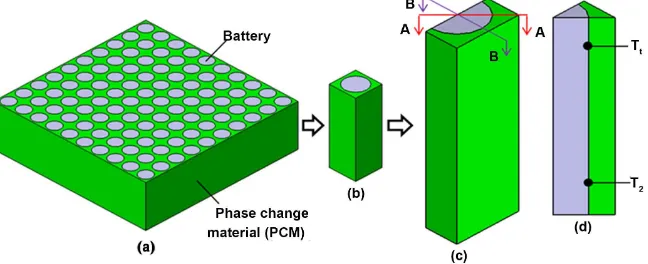
large size battery modules is established (Figure 1). The batteries are arranged in 10 × 10 array, and the phase change materials are filled into the gap of the batte-ries. Considering the large geometric size of the whole module, it is difficult to realize in the simulation, so the model needs to be simplified. In this paper, the heat dissipation around the battery module is neglected, and the feature units in the thermal management model are selected as the research object. Because the battery has axisymmetric characteristics, the three-dimensional numerical model for 1/2 battery is selected as the simulation model to calculate.
In this paper, the battery spacing is 4 mm, and the gap between batteries is filled with the PCM. Considering the complex winding structure inside the real battery and the anisotropy of its thermal conductivity, it is difficult to conduct the real battery model. In general, the complex winding structure inside the bat-tery will be neglected in the simulation. A lumped model of thermal conductivity anisotropy is established for the real battery to simulate [8]. In order to facilitate the construction of follow-up experimental devices and accurately control the different heating powers of the battery, the mock-up battery is used to replace the real battery for simulation. The mock-up battery is a profiled battery, which has the same size as 18,650 cylindrical battery. And the material is aluminum. In the center of the mock-up battery there is a circular hole with the diameter of 6 mm and the depth of 55 mm. An electric heater is placed in the hole to simulate the heating condition of the battery at different discharge rates. And the main material is stainless steel. The diameter of the heater is 6 mm and the height is 42 mm as shown in Figure 2.
[image:3.595.212.536.548.680.2]In this paper, the paraffin is used as the PCM in the passive thermal manage-ment system which is purchased from Luer, Hangzhou. The thermo physical properties are shown in Table 1. The thermo physical properties of the mock-up battery and the real battery are shown in Table 2. And the thermo physical properties of the real battery are referred from Ref. [8]. The real battery model here is the lumped model which neglects the internal structure. And its thermal conductivity is anisotropic. The thermal conductivity perpendicular to the
Figure 1. Numerical model of the PCM thermal management system, (a) the overall sys-tem, (b) the single battery numerical model, (c) the 1/2 battery numerical model, (d) the schematic of the temperature monitoring points in A-A cross section.
Figure 2. The mock-up and the real cylindrical batteries.
Table 1. The thermo-physical properties of the paraffin.
Density
(kg/m3) Specific heat (J/kg⋅K) Latent heat (J/kg) Melting temperature (˚C) Thermal conductivity (W/m⋅K) Viscosity (kg/m⋅s) coefficient (1/K) [10] Thermal expansion
880 2000 255,000 41-44 0.13 0.01 0.00091
Table 2. Thermo-physical properties of the mock-up and the real batteries.
Materials Density (kg/m3) Specific heat (J/kg·K) Thermal conductivity (W/m·K)
Aluminum 2719 871 155
Steal steel 7930 500 16
Real battery [9] 2510 1028 1.63(⊥) 36.96(∥)
interface is 1.63 W/m·K, and the thermal conductivity parallel to the interface is 36.96 W/m·K. It is noteworthy that the total heat capacity of the mock-up bat-tery used in this chapter is 40.20 J/K, which is very close to the total heat capacity of the real battery of 42.68 J/K.
2.2. Governing Equation and Boundary Conditions
In this paper, the following assumptions are made in the modeling process of passive thermal management model for phase change materials of battery mod-ules.
1) The liquid paraffin in the melting process is laminar flow and incompressi-ble Newtonian fluid.
2) It is assumed that the thermophysical properties of PCM do not change during melting.
3) The Boussinesq’s approximation is used to model the buoyancy effect of the PCM. The density change of paraffin during the melting process is not consi-dered.
4) The effect of radiation heat transfer is neglected.
The governing equations of PCM are given as follows [9][10].
[image:4.595.57.538.367.442.2]The continuity equation,
( )
0t
ρ ρ
∂
+ ∇ ⋅ =
∂ V (1)
The momentum equation,
(
)
2(
)
ref
P T T
t
ρ∂ +ρ ⋅∇ = −∇ + ∇µ +ρβ − +
∂
V V V V g S (2)
The energy equation,
(
H)
(
H)
(
k T)
t ρ ρ
∂ + ∇ ⋅ = ∇ ⋅ ∇
∂ V (3)
In the above governing equations, ρ is the density of liquid paraffin, V is the velocity vector of liquid paraffin, P is the pressure, μ is the dynamic viscosity, β
is the thermal expansion coefficient of liquid paraffin, g is the gravity vector,
Tref is the reference temperature, S is the momentum source term and K is the
thermal conductivity. The enthalpy-porosity method is used to solve the phase transformation problem [10]. The melting level of the PCM is expressed by the liquid fraction γ. The enthalpy H in the above equation is defined as follows:
d ref
T
ref T pcm
H h= +
∫
c T+γL (4)Href is the enthalpy at the reference temperature, L is the latent heat, and liquid
rate γ is defined as follows:
(
1) (
1 2 1)
1 22 0,
, 1,
m
m m m m m
m
T T
T T T T T T T
T T γ < = − − ≤ ≤ > (5)
In the above equations, the values of γ = 0 and 1 represent the solid and liquid phases of paraffin respectively, and the value of γ between 0 and 1 indicate the mushy zone. Tm1 and Tm2 represent the lower and upper limits of the melting temperature of paraffin, respectively.
The battery heating power and the boundary conditions in the simulation of the PCM passive thermal management are set as follows. Here, the 1/2 numeri-cal model of the batteries shown in Figure 1 is used to simulate the calculation. In the preliminary research process, the actual heating condition of the batteries is not considered. Here, the heating power is set to a constant value. In the benchmark case, the heating power of the batteries is set to a constant value. For 3 W, the heating power density of the electric heating rod is 252,668 W/m3. Considering the symmetry of the model, the symmetry surface is set around the model. The top of battery and PCM is set as natural convection surface, the convection heat transfer coefficient is 5 W/m2·K, and the bottom is set as adia-batic surface. In order to study the melting rule of phase change materials and the temperature rising trend of batteries at a constant heating power, the heating time is set to 2400s. In the simulation with Fluent 17.0, two temperature moni-toring points, T1 and T2, are set at the positions of 10 mm above and below the battery wall to monitor the temperature change during the heating process. The
temperature monitoring points are located at the A-A section, as shown in
Figure 1, and the liquid rate of PCM around the battery is monitored. When using ANSYS to mesh the simulation model, the global maximum mesh size is set to 0.4 mm. Considering the complexity of melting calculation of PCM, the local mesh of PCM area is refined, and the grid independence is verified. The fi-nal mesh number is 468,832. The time step optimization results show that the time step size of 0.2 s can meet the accuracy requirements, and thus the time step size is set to 0.2 s.
3. Results and Discussions
3.1. Comparison between the Mock-Up Battery and the Real
Battery
In order to verify the effectiveness of the simulated batteries in this paper, the temperature rise and PCM melting of the simulated batteries under passive thermal management of phase change materials are compared with that of the real batteries.
In this paper, the average values of temperature monitoring points T1 and T2 are used as the battery temperature. The temperature rise and the PCM liquid rate change of the simulated and real battery models under the benchmark con-dition are shown in Figure 3. The results show that the two models have good consistency during the whole heating process. In the first 1800s, the temperature rise curves of the simulated model and the real model almost coincide. After that, the two temperature rise curves gradually deviate. At the end of 2400s, the temperature difference between the two models is about 3 C. From the point of view of PCM melting situation, PCM around the battery begins to melt at 300 s. Because the simulated battery material is aluminum and its thermal conductivity is much higher than that of the real battery, the PCM around the simulated bat-tery model melts faster. For the real batbat-tery model, its radial thermal conductiv-ity is only 1.63 W/m·K, and the heat transfer from the inside of the battery to the outside wall is relatively slow, so the melting phase of PCM around the simu-lated battery model is faster. For hysteresis, the melting end time of PCM around real battery model is about 100 s later than that around analog battery.
The comparison between the simulated battery model and the real battery model shows the validity of the simulated battery. Using the average tempera-ture of the upper and lower parts of the simulated battery as the temperatempera-ture rise of the real battery without too much deviation can simplify the simulation model and reduce the computational complexity.
3.2. Battery Temperature Evolution in PCM Thermal Management
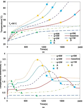
In order to analyze the role of phase change materials in passive thermal man-agement of batteries, the heat dissipation of batteries under 1 - 6 W heating power is studied. The results are shown in Figure 4.When the battery wall temperature reaches the melting temperature of the PCM, it begins to melt, and the time is marked as point A. As shown in Figure 4,
Figure 3. The comparisons of the battery temperature rise and the PCM liquid fraction between the mock-up and the real batteries.
Figure 4. The battery temperature results under the PCM passive thermal man-agement at different heating powers. (a) Battery temperature evolutions; (b) the temperature difference between battery top and bottom.
[image:7.595.228.519.300.676.2]the battery temperature increases quickly before point A. In baseline case, the battery wall temperature increases to the melting temperature of the PCM in 300 s. After the melting of the PCM, it absorbs large amount heat of the battery and thus the temperature rise of the battery is slowed down significantly. Compared with the battery temperature rise of 15˚C before the PCM melting in the first 300 s, it is takes 1388 s for the battery temperature rise of 15˚C after point A. The temperature difference between the battery top and bottom decreases after point A as is shown in Figure 4(b). This is because the melting of the PCM absorbs the battery heat quickly. Then, with the heating of batteries and the melting of the PCM, the temperature difference between the battery top and bottom tem-peratures of batteries shows in parabolic form. The maximum temperature dif-ference is recorded as point D. As the PCM melts completely, the battery tem-perature rising trend gradually accelerates, while the temtem-perature difference be-tween the battery top and bottom decreases to the steady state, which is called point E the end of the melting.
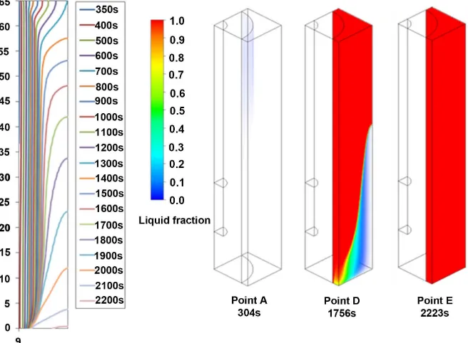
The PCM liquid fraction evolutions under different battery heating powers are shown in Figure 5. At low heating power of 1 W and 2 W, the battery tempera-ture remains below or around 50˚C during the heating time, and the liquid frac-tions of the PCM are 0.32 and 0.84 at the end of heating, respectively. In which the PCM passive thermal management shows good heat dissipation perfor-mance. When the heating power of the battery is increased to 3 - 6 W, the PCM melts completely within 2400 s.
The solid-liquid interface evolutions of the PCM at A-A cross section in the PCM passive thermal management for battery are shown in Figure 6. It can be seen that because the electric heater is located in the upper part of the battery, the temperature of the top wall of the battery reaches the melting temperature of the PCM first, so the PCM begins to melt at the top wall of the battery. With the heating of the battery, the melting front of the PCM moves to the right gradual-ly. At 1300s, the PCM of the top of the numerical model melts completely, and the melting front moves downwards, and the PCM at the top of the middle height of the battery melts completely at 1756s. Due to the effect of the gravity, the temperature of the liquid PCM near battery wall is higher than other places, which results in a larger convection velocity, and makes the convection of the liquid PCM at the bottom and the melting absorption of the solid PCM heat of the battery reach the maximum value, and the temperature difference between the battery top and bottom also reaches the maximum value.
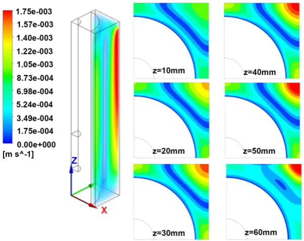
Figure 7 shows the distribution of the convection velocity of the liquid PCM at the end of PCM melting of point E. It can be seen that the maximum convec-tion velocity of the PCM is 1.75 × 10⁻³ m/s, which appears at the farthest posi-tion from the battery. The results of velocity contour at different battery heights show that the convective velocity of PCM is the highest in the upper part of the battery, and the liquid PCM moves upward near the battery wall and downward at the farthest distance from the battery to form a convective loop. Therefore, the
Figure 5. The PCM liquid fraction evolutions under the PCM passive thermal manage-ment at different heating powers.
Figure 6. The solid-liquid interface of the PCM at the A-A cross section during the melt-ing process and the visualization of the PCM liquid fraction behind B-B cross section.
region with the velocity around 0 appears in the middle of the PCM, as shown of the blue part in Figure 7.
3.3. Effect of Battery Spacing
Battery spacing affects the filling amount of the PCM in the battery module, which in turn affects the thermal performance of the battery. Figure 8 shows the battery temperature evolutions under different battery spacing at the heating
[image:9.595.209.537.332.573.2]Figure 7. The velocity distribution of the liquid PCM and the velocity contours at different heights of the battery at the characteristic point of E.
Figure 8. The battery temperature evolutions under different battery spacings at the heating power of 3 W.
power of 3 W. The results show that as the increase of battery spacing, the filling amount of the PCM increases, and the temperature rise rate of the battery de-creases, and gradually tends to be flat, which means that the battery has better thermal performance.
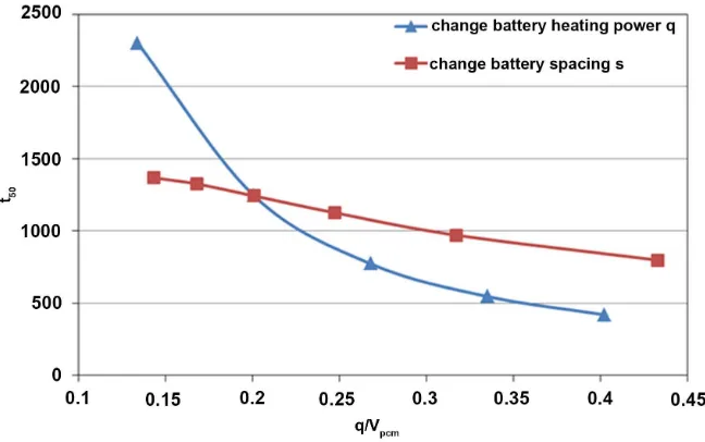
Usually, the acceptable temperature range at the operation of lithium-ion bat-teries is 20˚C - 60˚C. When the battery temperature increases above 50˚C, the capacity of lithium-ion batteries will decline rapidly [11][12]. In this paper, the time t50 representing the battery temperature increases to 50˚C is used to eva-luate the thermal performance of the PCM passive thermal management system. As is shown in Figure 9, t50 is used as the longitudinal axis, and q/Vpcm is used as
[image:10.595.229.521.354.529.2]Figure 9. The results of the t50 at different q/Vpcm while varying the battery heating power or the battery spacings.
the horizontal axis to describe the different thermal performances of the battery when changing the heating power or the battery spacing. The q/Vpcm increases or decreases with the increases of the heating power q or the battery spacing s. When the heating power increases, the time of the battery temperature reaches 50˚C gradually increases. The time t50 decreases from 2300s to 420s when the heating power of the battery is increased from 2 W to 6 W. As shown in Figure 9, with the increase of battery spacing s, the thermal control time t50 increases li-nearly with the q/Vpcm. The larger the battery spacing is, the longer the time that battery temperature increases to 50˚C is. The t50 increases from 799 s to 1368 s when the spacing s increases from 1 mm to 6 mm.
4. Conclusions
In this paper, the passive thermal management system for the battery module by using PCM filled in the gaps and the representative numerical model for 1/2 battery are established. The melting characteristics of the PCM and the battery thermal performance in the passive thermal management system are studied through the numerical simulation. The battery thermal performances under dif-ferent heating powers or battery spacing are analyzed. The conclusions are as follows:
1) The comparison of the battery temperature evolution and the liquid frac-tion between the two battery models show that it can be accepted through using the mock-up battery to replace the real battery in the simulation, and the devia-tions are little that almost can be neglected.
2) The characteristic points during the melting process of the PCM consist of point A—representing the start of the melting, point D—the maximum temper-ature difference between the battery top and bottom appears and point E—the end of melting process of the PCM. The maximum convective velocity of the
liquid PCM appears in the position which is far from the battery at the end of melting process.
3) Increasing the battery spacing can increase the filling amount of PCM in the battery module, thereby delaying the battery temperature rise. The results show that when the battery spacing is increased from 1 mm to 6 mm at the heating power of 3 W, the time for the battery temperature reaches 50˚C in-creases by 1.7 times, and thus the battery thermal performance is improved.
Conflicts of Interest
The author declares no conflicts of interest regarding the publication of this pa-per.
References
[1] Jarrett, A. and Kim, I.Y. (2011) Design Optimization of Electric Vehicle Battery Cool-ing Plates for Thermal Performance. Journal of Power Sources, 196, 10359-10368.
https://doi.org/10.1016/j.jpowsour.2011.06.090
[2] Mahamud, R. and Park, C. (2011) Reciprocating Air Flow for Li-Ion Battery Ther-mal Management to Improve Temperature Uniformity. Journal of Power Sources, 196, 5685-5696. https://doi.org/10.1016/j.jpowsour.2011.02.076
[3] Fan, L., Khodadadi, J.M. and Pesaran, A.A. (2013) Parametric Study on Thermal Management of an Air-Cooled Lithium-Ion Battery Module for Plug-in Hybrid Electric Vehicles. Journal of Power Sources, 238, 301-312.
https://doi.org/10.1016/j.jpowsour.2013.03.050
[4] Chen, D., Jiang, J., Kim, G.H., et al. (2016) Comparison of Different Cooling Meth-ods for Lithium Ion Battery Cells. Applied Thermal Engineering, 94, 846-854.
https://doi.org/10.1016/j.applthermaleng.2015.10.015
[5] Zhao, C., Cao, W., Dong, T., et al. (2018) Thermal Behavior Study of Discharg-ing/Charging Cylindrical Lithium-Ion Battery Module Cooled by Channeled Liquid Flow. International Journal of Heat and Mass Transfer, 120, 751-762.
https://doi.org/10.1016/j.ijheatmasstransfer.2017.12.083
[6] Al-Hallaj, S. and Selman, J.R. (2000) A Novel Thermal Management System for Electric Vehicle Batteries Using Phase-Change Material. Journal of Electrochemical Society, 147, 3231-3236. https://doi.org/10.1149/1.1393888
[7] Kizilel, R., Sabbah, R., Selman, J.R., et al. (2009) An Alternative Cooling System to Enhance the Safety of Li-Ion Battery Packs. Journal of Power Sources, 194, 1105-1112. https://doi.org/10.1016/j.jpowsour.2009.06.074
[8] Maleki, H., Wang, H., Porter, W., et al. (2014) Li-Ion Polymer Cells Thermal Prop-erty Changes as a Function of Cycle-Life. Journal of Power Sources, 263, 223-230.
https://doi.org/10.1016/j.jpowsour.2014.04.033
[9] Sciacovelli, A., Colella, F. and Verda, V. (2013) Melting of PCM in a Thermal En-ergy Storage Unit: Numerical Investigation and Effect of Nanoparticle Enhance-ment. International Journal of Energy Research, 37, 1610-1623.
https://doi.org/10.1002/er.2974
[10] Yang, H., Zhang, H., Sui, Y., et al. (2018) Numerical Analysis and Experimental Visualization of Phase Change Material Melting Process for Thermal Management of Cylindrical Power Battery. Applied Thermal Engineering, 128, 489-499.
https://doi.org/10.1016/j.applthermaleng.2017.09.022
[11] Väyrynen, A. and Salminen, J. (2012) Lithium Ion Battery Production. Journal of Chemical Thermodynamics, 46, 80-85. https://doi.org/10.1016/j.jct.2011.09.005
[12] Ramadass, P., Haran, B., White, R., et al. (2002) Capacity Fade of Sony 18,650 Cells Cycled at Elevated Temperatures: Part II. Capacity Fade Analysis. Journal of Power Sources, 112, 606-613. https://doi.org/10.1016/S0378-7753(02)00474-3