USBBDM
Background Debug Module for the Motorola / Freescale HCS08 and HC(S)12
series Microcontrollers
USERS MANUAL
© Axiom Manufacturing, 2003 2813 Industrial Lane
Garland, TX 75041
972-926-9303 FAX: 972-926-6063 email: [email protected]
TABLE OF CONTENTS
1 USB BDM FEATURES... 2
2 WHAT YOU WILL NEED... 2
2.1 HARDWARE CHECKLIST... 2
2.2 SOFTWARE CHECKLIST... 2
2.3 TERMINOLOGY... 2
3 INSTALLATION AND STARTUP ... 3
3.1 SOFTWARE INSTALLATION... 3
3.2 HARDWARE INSTALLATION AND START-UP... 3
3.3 OPERATION PROCEDURE... 4
4 USING THE USBBDM SOFTWARE ... 5
4.1 WINDOWS... 6
4.1.1 Register window ... 6
4.1.2 Program window ... 6
4.1.3 Data Window ... 8
4.1.4 Source Window ... 10
4.1.5 Watch Window ... 11
4.1.6 Window Notes:... 13
4.2 MENUS ... 13
4.2.1 File... 13
4.2.2 Edit... 14
4.2.3 Configure ... 14
4.2.4 File I/O ... 17
4.2.5 Debug ... 19
4.2.6 Window ... 20
4.2.7 Help ... 21
4.3 PUSH BUTTONS... 21
4.3.1 Reset Push Button ... 21
4.3.2 Step F5 Push Button ... 21
4.3.3 Nstep Push Button ... 21
4.3.4 StepOver F6 Push Button ... 21
4.3.5 GO (BREAK) F7 Push Button ... 21
4.3.6 Trace Push Button ... 21
4.3.7 RuntoCursor F8 Push Button ... 22
4.3.8 ExecMacro Push Button ... 22
5 MACRO FILES ... 22
5.1 MACRO COMMANDS... 22
5.2 RESET OR INITIALIZATION MACRO... 23
5.3 PROGRAM OR ERASE MACRO... 23
5.3.1 Erase Macro Example ... 23
5.3.2 PROG Macro Example ... 24
5.3.3 Debug Menu Program and Erase Flash EEPROM ... 24
5.3.4 Algorithm Application Programs ... 25
5.3.5 Default Program and Erase Macro ... 25
6 INI FILE... 26
USBBDM User Manual V1.1
1 USB BDM Features
The USB BDM is a source-level debugger for Motorola / Freescale MC9S08 (HCS08), MC68HC12 and MC9S12 series (HSC12) microcontrollers. The BDM provides fast access to all target device resources via a PC USB port and the target device Background Debug interface. The USBBDM module connects directly to a standard Motorola 6-pin BDM connector on your target development board. No expensive emulator or PC add-on card is required – your PC
communicates with the BDM module via a standard USB port (all cables included).
Powerful, easy to use Windows Debugging software gives you advanced real-time debugging features including:
• Single step, Step Over, Go and Trace execution
• Up to 100 Software Breakpoints, 2 hardware breakpoints typically (device dependent)
• Non-intrusive memory and register view or modify in real time
• Copy, Paste, Move, Fill target memory thru windows clipboard
• Built-in on the fly assembler / disassembler
• Automatic loading of Source level symbol definitions
• Variable Watch window – use source symbols or make up your own variables on the fly
• Open unlimited number of unique Program and Data windows
• Macro scripting support automates many initialization, memory and file operations
• Register modification and logging during program execution
• EEPROM and FLASH Programming support
2 WHAT YOU WILL NEED
2.1
Hardware Checklist
Host A IBM compatible computer with USB port Memory Minimum of 4 megabytes
Display VGA compatible
Target A powered on target board with a HC12 Microcontroller and 6-pin BDM connector (Target Development Board)
USBBDM Background Debugger (provided) Cables USB port and target cables (provided)
2.2
Software Checklist
Operating System Windows 98/ME/XP/NT/2000
Assembler Motorola HC(S)12 or HCS08 compatible assembler
Debugger software USBBDM Windows-based background debugger software (provided)
2.3
Terminology
This manual applies the following terms:
Host:
Personal Computer operating the BDM cable and software.
Target:
Development board or Device the BDM is controlling the operation of.
BDM:
The USBBDM cable or supporting software on the host.
WORD:
16 bit binary or hex value.
3 INSTALLATION AND STARTUP
3.1
Software Installation
See the quick start guide for detailed installation instructions.
Use the following set-up procedure to enable the USBBDM debug software on your PC:
1. Insert the “USBBDM” CD into your PC drive. Do not connect the USBBDM to the PC USB port yet. 2. Execute the file named USB-BDM-SETUP.EXE using the Windows “RUN” command.
3. Follow the on-screen instructions which will install the software onto your hard drive.
4. Install the USB cable into the USBBDM USB connector and install the other end of the USB connector into an available USB port on the host PC (no target board connected at this time). The PC should recognize the USBBDM automatically when the cable is connected. The “new hardware found” message should occur, follow these steps to install the USB driver for the BDM:
a) Open the Windows new hardware found wizard by clicking on the prompt window displayed. b) Select the “Install from list or specific location” Proceed to install the driver and search the USBBDM
software installation directory. Windows should locate the ftd2xx.inf file automatically in the installation directory. Use this file to install the driver.
c) If Windows prompts that the driver is not certified, click “Continue anyway”.
d) Windows should now recognize the USBBDM when it is removed and re-inserted into the PC USB port. Windows will issue 2 beeps and will not present the new hardware found message if the device is recognized. If 3 beeps are heard the device is not recognized and the driver will need reinstalled, see the troubleshooting section for directions to re-install the driver.
5. Remove the USBBDM cable from the PC USB port and proceed to hardware installation.
3.2
Hardware Installation and Start-up
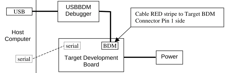
Install the software first before installing the hardware. There are two connections on the BDM. The USB connector is a standard USB device interface to the PC. The other connector is a 6-pin ribbon cable connector that should fit any standard Motorola / Freescale HCS08 or HC(S)12 BDM header. See Figure 1 for a connection diagram.
Figure 1 Shows a typical setup using the USBBDM background debugger. The serial port connector is optional since it may not be available on your target board.
Host Computer
USBBDM Debugger
Target Development Board
BDM serial
USB
[image:4.612.144.525.539.664.2]serial Power
Figure 1. Typical Setup
USBBDM User Manual V1.1
Follow these steps IN THIS ORDER to install and connect the USBBDM hardware:
1. Target board is powered off and HC12 is optioned for Single-chip Mode with the MODA and MODB selections. If target board provides a MODC option, install option or select Special Mode position.
2. Connect the BDM 6 pin ribbon connector to the BDM or DEBUG header on your Target Development Board. Be sure to line up the side of the connector closest to the RED STRIPE to Pin 1 of the BDM socket.
3. Install the USBBDM USB connector into the host computer USB port. See the Software installation section if 3 beeps are heard or the computer reports “new Hardware found”.
4. Apply power to or power on the Target Development Board.
5. Launch the USBBDM software. See the Trouble shooting section if the “Device Not Found” message appears. The “Target not powered” warning should be resolved by applying power to the target board. Other warning messages should be resolved by target configuration in the USBBDM software configuration.
6. Select the software Configure – Configure Target menu. Complete the entries for the Target board / device connected. The Clock setting will be the default bus clock (E clock) or 50% of the oscillator frequency provided to the target device.
7. After completing the Configure Target menu, the BDM should establish communication with the target device. Click the USBBDM software RESET button and verify communication by selecting the PC (program counter) register in the register window and modifying its value to 1000 or 4000. The PC register should update and Program window base address move to the new PC location. No “***” values should be displayed.
No target communication sample window.
3.3
Operation Procedure
" Set target device to Single-Chip Mode and enable MODC if optioned.
" Connect USBBDM, target board, and host computer.
" Power on Target board
" Launch USBBDM software.
" Perform CONFIGURE – CONFIGURE TARGET options and save settings. After changing options click the USBBDM software RESET button or if need be close the software and re-launch to establish communication with the new settings.
" Press the software RESET push button and verify target device is communicating with host computer via the USBBDM. Close and re-launch USBBDM software if target configuration is changed.
" Configure Compiler, File loading or Reset macros, and other options as wanted.
" Use “Files – Load S19 or Hex” operation to load object code into target memory (RAM type). If compiler type is selected correctly and necessary compiler debug output files are present; the source code will be loaded also in the SOURCE window. The PC register will update to the Start point of the application program if configured to do so.
" Start the debug session.
" See Programming Operations section of this manual to load applications in Flash or EEPROM type memory space.
Main Screen and Target is communicating sample window.
4 USING THE USBBDM SOFTWARE
When the USBBDM software is started with a good configuration and target communication, a screen display similar to above should be present. Window placement and size may differ from the above example. Windows in the screen view can be opened, closed, sized, or arranged to the user’s preference.
Main Screen operation notes:
1. The current loaded file is displayed on the top Title bar of the screen.
USBBDM User Manual V1.1
3. Red text in the Program or source windows indicates the current target program instruction to be executed next. The ‘+’ symbol after an address or line number denotes the current Program Counter position.
4. The highlighted line (blue - green) is the window cursor position. The cursor position will be applied for “Run To cursor” or in-line assembly operations.
5. A highlighted (pink) address in the Program window or line number in the Source window indicates a Breakpoint is set on that instruction.
The USBBDM software desktop screen has three major parts: Menus, Push Buttons, and Windows. A description of each window follows.
4.1
Windows
There are 5 types of windows provided on the BDM desktop screen: Register, Program, Data, Source, and Watch. The Register window is dedicated and always available. All other windows can be opened or closed with the Window menu. Multiple Program and Data windows are available to view different sections of memory. The Trace Push Button will open a pop-up type window to display trace results.
4.1.1
Register window
The register window provides target device CPU internal core register view and access. Only one register window is possible. A register value change during code execution will be indicated in RED text.
PC = Program Counter or Instruction pointer SP = Stack Pointer register
IX = Index ‘X’ register IY = Index ‘Y’ register
A = Accumulator ‘A’ or MSB of the ‘D’ register
B = Accumulator ‘B’ or LSB of the ‘D’ register D = Accumulator ‘D’ or double accumulator A | B
SXHI = CCR (condition code register) high nibble bits. S = Stop bit, X = X bit, H = Half Carry flag, I = Interrupt bit NZVC = CCR (condition code register) low nibble bits. N = Sign flag, Z = Zero flag, V= Overflow flag, C = Carry flag To change the contents of a register, right click the register value to be modified, and type in the new value in hex format. The register will be updated after the least significant digit (right most hex number) is entered. If the register window is not visible it will be available in the lower left corner of the BDM screen to reopen. Note: another window may obstruct the view to reopen the register window, move the obstructing windows to find the register window.
See the target device CPU reference manual for more details on the core registers and their operation.
4.1.2
Program window
Displays the program memory in three parts left to right on the display: Address, Opcode, and assembly mnemonics. The assembly mnemonics are interpreted (disassembled) according to the data in the target memory. Symbols from the listing or symbol table may also be shown if they are loaded.
Breakpoints can be set or cleared by a left click on the address field. A set breakpoint is indicated by a pink highlight on the address field.
More than one Program Window may be opened.
A right click in the Program window will present the Program Pop-up menu. 4.1.2.1 Program Window Pop-up menu
The Program Pop-up menu provides utility operations and Program window settings. A right click in the Program window will present the Program Pop-up menu.
Run to cursor Run application code to the indicated cursor position in the Program window and stop.
Run to Label (or address)
Run application code to the identified label or address location and stop. See Run to Label below.
Edit Edit the instruction on the cursor line, in-line assembler operation. See Edit below for more detail.
Go to Break Point Change Program window memory view to a current breakpoint address. See Go to Break below.
Go to Address Change Program window memory view to a particular starting address, See Go to address below.
Go to Symbol Change Program window memory view to a symbol address. See Go to Symbol below.
Go to PC Change Program window memory view to current PC register address. PC = Address at
Cursor
Change PC register value to the current address selected by the cursor.
Clear all BKPT Clear all set breakpoints.
√ Program Page Enable
If checked, Paged Program operation of Program window is enabled. Program window view for addresses above 64K bytes (0xFFFF) will be viewed via the Program Page. Do not use this setting if loaded file is not Paged.
Run to Label or Address:
Pop-up window will query for the Label name, symbol name or address value to run to then stop execution.
Edit:
Allows Editing of the program in memory at the current Cursor Position. This is an in-line assembly operation and must be performed in Ram type memory space or the new instruction will not be installed.
Standard assembly mnemonic instructions can be typed in this box. The operands in the instruction (such as an immediate number, an extended address) must be either hexadecimal numbers or symbols used in the program (if symbols are loaded). For example type in instructions like LDD #1234, LDD $4321, or BRA MY_SYMBOL. If an error is found in the
USBBDM User Manual V1.1
Go to Break Point:
If any break points are set, this menu item will quickly move the Program window cursor to one of the breakpoint locations. The Break Points pop-up will open showing the currently set breakpoints. Select one of the breakpoints to go to or delete the breakpoint.
Go to Address:
Move Program window cursor to an address location or select an address from a list previously entered by clicking on the down arrow. The cursor will change to the address selected.
Go to Symbol:
If a symbol table is loaded, use this menu to jump quickly to one of the symbols. This is very helpful if setting a breakpoint at a subroutine during debugging is wanted. Click on the down arrow in the dialog box, all the symbols loaded will show up for selection.
4.1.3
Data Window
Displays target memory content by starting address in left column followed by memory data. More than one data window can be opened. The window title bar indicates the view mode and if page views are enabled. See the Pop-up window options for more details.
Corresponding ASCII text values in the data can be displayed on the right of the hex data when enabled. Also, data width and byte or word view is selectable in the Pop-up window options. To edit values in the data window place the cursor or left click on the data value to be changed and type in the new value. Note that the last digit (right digit) of the word or byte must be
4.1.3.1 Data Window Pop-up menu
The Data Pop-up menu provides utility operations and Data window Page View settings. A right click in the Data window will present the Data Pop-up menu. Note that only one Page view setting may be selected per data window.
Go to address Change Data window memory view to a particular starting address, See Go to address below.
Go to symbol Change Data window memory view to a symbol address. See Go to Symbol below. Go to PC Change Data window memory view to the current PC register address.
Fill Block Fill a range or block of addresses with given data. See Fill Block details below. Move Block Move a block of data from one starting address location to another. See Move Block
details below. Toggle data per
Line (16 or 8)
Change the data view width between 16 bytes / 8 words or 8 bytes / 4 words.
Display as Word (Byte)
Change the data view between 8 bit Byte and 16 bit Word view.
(√) Display ASCII data
If checked, will enable the corresponding ASCII text represented by the data will be viewed on the left side of the data window.
(√) Program Page view
If checked, will enable Program Page view in the data window. Memory above 64K byte (0xFFFF) addresses will be viewed by Program Pages. Do not use this setting if Program Paging is not supported by the target device.
(√) Data Page view
If checked, will enable Data Page view with access to the Data Page at the 0x7000 address. The target device must support Data Paging to use this view.
(√) Extra page at 0x0000 view
If checked, will enable Extra Page view with access to the Extra Page at the 0x0000 address. The target device must support the Extra Page to use this view.
(√) Extra page at 0x0400 view
If checked, will enable Extra Page view with access to the Extra Page at the 0x0400 address. The target device must support the Extra Page to use this view.
(√) Not Page Mode
If checked, will disable Page views and provide a standard linear memory view. This view is compatible with all targets.
Go to Address:
Move Data window base to an address location or select an address from a list previously entered by clicking on the down arrow. The cursor will change to the address you select.
Go to Symbol:
If a symbol table is loaded, use this menu to move the data window to one of the defined symbol locations. This is very helpful in finding and viewing variable data. Click on the down arrow in the dialog box, all the symbols loaded will show up for selection.
Fill Block:
USBBDM User Manual V1.1
Move Block:
Move or copy a block of data from one memory location to another memory location. The from address and to address represent the block range of memory that will be moved or copied. The move to address is the base or starting address of the memory to be updated. The addresses should be an even number boundary due to the block operation operates in word or 16 bit data size.
4.1.4
Source Window
Displays symbolic source code of current file loaded by the BDM if the source is compatible and can be found on the host.
The highlighted line is the current cursor position. A ‘+’ symbol next to the line number and red text denotes the current program counter position.
Breakpoints can be set or cleared by left clicking on the line number. The line number will be highlighted in pink if a breakpoint is set on that line. Note that Breakpoints will only set on instruction source lines. Source window breakpoints will not set on comments, text, or Label only source lines.
Right click in the source window will open the Pop-up menu for the source window.
4.1.4.1 Source Window Pop-up menu
The Source Pop-up menu provides utility operations and window settings. A right click in the Source window will present the Source Pop-up menu.
Run to cursor Run application code to the indicated cursor position in the Source window and stop. If the cursor is not on a valid instruction line, the program will not execute.
Go to PC Change Source window view to current PC register address.
Go to Break Point Change Source window view to a current breakpoint address. See Go to Break below.
Open Source file Open the source file indicated. See Open source File below. Find Find a text entry in the source file. See Find below.
Find next (F3) Find the next text entry identified by the Find operation.
TAB size Set the source window view Tab character size. See TAB size below.
Go to Break Point:
Open Source file:
Prompt window opens to Select source file to open in source window. The down arrow will provide a list of available source files. The BDM software will generate a source file named “info.src” to display source information.
Find:
Prompt window opens to enter text string to be found in the source file. Match case option allows exact text match to be found otherwise upper or lower case is not checked. The cursor will move to the line that contains the matched text when the operation is performed. If the text cannot be found, an error prompt will be displayed.
Tab size:
Tab size effects the source window view. A prompt window opens to set the Tab size space count. Tab size space count can be set from 1 to 8 spaces.
4.1.5
Watch Window
USBBDM User Manual V1.1
4.1.5.1 Watch Window Pop-up menu
The Watch Pop-up menu provides utility operations for the Watch window. A right click in the Watch window will present the Watch Pop-up menu.
Edit Edit the value of the contents of the watched variable highlighted by the cursor. See Edit below.
Add variable Add a new variable to the watch window. See Add and Modify below.
Modify setting Modify the settings of the variable highlighted by the cursor. See Add and Modify below.
Move up Move position of watched variable highlighted by the cursor up the list in the watch window.
Move down Move position of watched variable highlighted by the cursor down the list in the watch window.
Delete Delete the watched variable highlighted by the cursor from the watch window. Open config Open a Watch window configuration file. Watch window set-up can be saved in
configuration files. See Watch configuration save and restore below. Save config as Save the current Watch window configuration for future use. See Watch
configuration save and restore below.
Edit:
Allows Editing the watched variable contents. The variable at the cursor position will be prompted in a edit window. A new value can be typed in to the variable.
Add or Modify setting:
Allows adding or changing the settings of a watched variable. The Modify setting will open the prompt window for the variable highlighted by the cursor.
Symbol: The name it may be picked from the loaded symbol list with the down arrow or a reference name typed in.
Address: The memory location of the variable can be typed in. If it is defined in the symbol list the address will be inserted
automatically.
Display as: Select the number base or text string setting for the
variable view wanted. The view type will be displayed in the watch window next to the variable name in parentheses. Example: PPAGE = Hex value, watch display = PPAGE (H) xx
Length: If the variable is a string, the length should be set to the character count to be displayed. Example: Value_out = a string variable with 8 character ASCII digits or text. Length = 8, Address = first character or lowest address, word length = do not care.
Page: The location of the variable if it is on a Paged access or in the linear memory space (No Page).
Word Length: If the variable is NOT a string and is a number, the Word length selection will set the size of the number to be displayed. 8 bits = byte, 16 bits = word or 2 bytes, 32 bits = long word or 4 bytes.
Open configuration or save configuration as:
Allows saving a watch window configuration or loading a previously saved configuration. Both operations open the pop-up window to query for a file to open or file name to save. The .cfg extension is applied by default.
4.1.6
Window Notes:
1. All windows can be minimized and maximized. The windows maybe arranged in any order and stacked for preference.
2. Opening many program and data windows will slow down debugging since it takes time to update the contents of these windows.
4.2
MENUS
The menu items are provided under the title bar of the screen. These are the main screen menu items: File Edit Configure File I/O Debug Window Help
The underlined character in the menu item name will provide the ‘ALT – Character’ menu launch via the keyboard. A mouse click will also select the menu wanted.
4.2.1
File
The File menu provides source input and macro file operations or a means to Exit the USBBDM software.
Load S19 or HEX Load a file in Motorola S19 format into RAM type memory on the target board or device. A standard file / folder browser window will open and default file extensions S19, SX, or HEX will be listed. See the CONFIGURE – Configure Compiler menu for S record format and source code type options also.
Execute Macro Load and execute MACRO script file. A standard file / folder browser window will open and default file extension MAC will be listed. Standard macros are provided in the installation directory sub-folder: macros. If the selected file is successfully opened, it will be stored into the INI file for use next time. See the Macro Writing and Macro Push Button sections for more information on Macros.
Load symbol Load a symbol file for use by the debugger. The symbol file should be created by the compiler or assembler and will facilitate symbolic debugging. If a compatible LISTING file exists, the symbol table will be loaded automatically. See the CONFIGURE – Configure compiler menu selections also for automatic source and symbol loading.
Exit Exit the USBBDM software program. If the Configure – Save on Exit item is checked, the current screen and file configurations will be saved prior to exit.
USBBDM User Manual V1.1
4.2.2
Edit
The two functions under Edit Menu, "Copy to Clipboard" and "Paste from Clipboard" allow you to transfer data between the target and the Windows clipboard. The data copied to or from the clipboard should be ASCII character in hexadecimal format (for example 3F23). Each data word is separated by a new text line break (CR/LF characters).
Text list type example: FFFF
BFDB 1A3C 45E1 EF5E …
The program will verify this format before data is copied into memory.
Copy to Clipboard: Copies a range of data from the target memory to the Windows clipboard. The starting and ending memory addresses to be copied to the clipboard must be provided. Click the ‘Ok’ button to copy the contents of the memory to the clipboard in hexadecimal format.
Paste from Clipboard: Copies the contents of the Windows clipboard to target memory. The starting address where the data will be copied to must be provided. The contents in the clipboard should contain one 4 digit hexadecimal number per text line. As soon as the end of the clipboard content or an error is encountered (for example, an invalid hexadecimal value), the copy process will terminate.
4.2.3
Configure
The Configure Menu provides the primary development interface setups. Seven menu items are provided: Configure Target
Configure compiler, macros, font Program window scroll range Data window scroll range Non-intrusive update Save settings
4.2.3.1 Configure Target
Sets the target device type and characteristics for the BDM interface. Communication with the Target may not occur until the Target device and BDM Clock Frequency items are set correctly.
Target device: Select device type from the pull-down menu. Note HC12 type is shown, HCS8 software will provide the HCS08 targets.
BDM clock frequency in KHz: Select the operating frequency of the target device BDM port. This frequency is typically 50% of the oscillator frequency provided to the target device. Values of 1000, 2000, 4000, 8000, 12000, 16000, 20000, and 24000 are provided, other values must be typed in. Mode after Reset: Select the target device operating mode wanted for development. Note that the hardware setting should have the target device set
to single-chip mode. Note also that a macro file or application code execution may also modify this setting after reset has occurred.
PC after reset or load (hex): Select the Program Counter (PC) register or Instruction pointer default location. The PC register may be defined a fixed location, a memory address to load from, or loaded from the S record S9 line content. The assembler or compiler applied must support the S9 record content information. The S9 supported content will be the code start location of the S record file or the Reset vector.
• In address This option allows the PC to be set to the memory location (FFFE in this case) content.
Example: The address FFFE reflects the default Reset vector location of the target device so when a file is loaded, the PC will be set to the reset vector defined in the loaded file.
• Is address This option allows the PC to be set to a fixed location, 4000 hex in this case.
Example: The address 4000 hex reflects the value of the PC register after a Reset or file load. This option should be applied for files that do not contain a Reset vector or when no file is being loaded and the PC is to be defined.
• In S9 This option allows the PC to be set to the content of the S record S9 line.
Example: The assembler or compiler applied provides code start location address in the S record S9 line content. The PC will be set to the code start value defined in the loaded S record. Note: The S record will need to be loaded to set the PC.
Breakpoints: Select Breakpoint type of Software or Hardware. Note that breakpoints must be placed on an instruction opcode and not on data or operands.
Software breakpoints are practically unlimited in number but must be placed in RAM type memory space. The BDM will modify the instruction at the desired breakpoint location with a BGND command to insert a software breakpoint in memory. Software breakpoints must be applied in RAM type memory and will not operate in Flash or EEprom type memory. Hardware breakpoints should be applied for Flash or EEprom (nonvolatile) type memory. See the Configure Target section for breakpoint type selection.
The user may insert a BGND instruction in the application code to force a dedicated software breakpoint on the BDM but this is not recommended practice.
Note: Software breakpoints or the BGND instruction will remain in Target memory when the BDM software is closed. Always reload the application file after launching the BDM software to prevent undesired operation. Hardware breakpoints must be supported by the target device and are limited in number to two typically. A hardware breakpoint can be set in any memory type. Hardware breakpoints do not modify the memory content. Run to symbol: Provides a start at symbol or label location. When enabled with a valid symbol defined (symbol is present in source or symbol tables), this feature will allow the application program to execute until the defined symbol is reached. This allows debugging to begin at a particular location in the application after an updated file is loaded.
FFFE
USBBDM User Manual V1.1
4.2.3.2 Configure Compiler, macros, font…
Three window tabs are provided in this screen to configure the compiler type, automatic macro execution, and screen font selections.
Compiler Tab: Selects compiler or assembler typefor source and symbol loading and S record address format. Note that Program Window will display disassembled memory content no matter the compiler selection.
Compiler: Select the compiler or assembler applied to generate the object code. Unsupported assemblers should apply the Free assembler setting. Unsupported C compilers may work with the GNU setting if the compiler generates ELF type output files. If the compiler applied to generate application code is changed, this setting should be changed also.
Debug is possible without picking the correct tool here, but access to symbols and the Source window will be blank, since source level debugging is not possible without the tool specific output (i.e. listing, map, elf file).
Address: Selects the S record addressing format (HC12 only). A standard S record file provides the Linear address format. A special Banked or Paged type S record may be provided for HC12 targets with memory capability over 64K bytes. This type of S record provides the Page Register value in the address field instead of location. Refer to the applied assembler or compiler documentation and options to determine if a Paged or Banked S record is being generated. Note that conversion utilities are available to change the S record format. Linear format should be applied by default.
Macro Files Tab: Provides automatic macro execution for file loading or after Reset. Select the file name and check the enable box to perform automatic macro execution. See the Macro Writing section of this manual for more details.
Macro file name before loading file: Select the macro to run prior to loading a new S record file. This type of macro would normally enable a particular feature or unlock a memory space for memory update on the target.
Macro file name after Reset: Select the macro file to run after a Reset has occurred. This type of macro will configure registers or load memory with data
prior to code execution. This macro type is applied to enable bus controls and bus type in Expanded Memory targets prior to loading or executing code. Typically this macro type is required on Expanded Wide targets and the default macros are provided for Axiom development boards.
Font Tab: Provides selection of screen font and character size.
4.2.3.3 Program Window Scroll Range
4.2.3.4 Data window scroll range
This setting will set the address range the Data window will display. The hex value placed in the setting window will be the largest address possible in the Data window. This setting should be large to be able scroll and view all of memory in the Data window or maybe limited to the Ram memory space for just Data view.
4.2.3.5 Non-intrusive update
Sets the update rate and enables the non-intrusive update of Watch window variables. Variables in the Watch window can be monitored during real time program execution by enabling the non-intrusive update operation. The update rate is 100ms minimum or a maximum of 10x a second.
4.2.3.6 Save setting
Saves the current configuration of the BDM screens and configurations. The information that is saved includes the windows opened, window size and position (including register, program, data, source, and watch windows), and the starting address of each data window. This information is stored in the programs INI file so the next time you start the program, these settings will automatically load.
4.2.3.7 Save on Exit
If enabled by a check mark next to the setting, the BDM software settings will automatically be saved when you exit the program. Whether or not this menu is checked, the starting address of each data window will always be saved in the INI file when the program exits. Care is needed when applying this option, accidental change the size and position of a window is possible if the BDM program is closed during a temporary change of the desktop. The "Save setting" option may be applied whenever the settings are correct for the preferred view.
4.2.4
File I/O
The File I/O menu contains powerful tools used to facilitate your program debugging. The BDM can read data from a file and place it into the target device ‘D” register with the Infile operation.. The contents of the ‘D’ register can also be sent to an output file with the Outfile operation. To use the this function a file name must be set-up first, then use the "Start" and "Stop" functions from the File I/O menu.
File I/O Menu:
Start Start the File input or output operation Stop Stop the file input or output operation
Infile Select the Input file and enable or disable file input. OutFile Select the output file and enable or disable file output.
4.2.4.1 Input File
To use an input file, apply a LDD (Load D command with the Extended Addressing Mode (LDD Label or LDD $1234 where Label or 1234 value is an effective address in memory) in the source code. Compile / assemble and load the application file with the BDM. Move the cursor in the Program Window
to the LDD ‘EXT’ (load D register by extended addressing) instruction. Select “Infile” from the FileI/O menu. A dialog window appears as shown >
USBBDM User Manual V1.1
Infile: Input file content should be simple text and be formatted as follows: 1111
2222 5AB9 …
Each entry represents a hexadecimal word (16 bit) value.
The File I/O menu START will start the input file operation. The file input operation will run until the end or the input file content or until the STOP menu item is selected. The operation cannot be monitored, stopped by breakpoint, stepped through, or traced.
4.2.4.2 Output File
To use an output file, apply a STD (Store D command with the Extended Addressing Mode (STD Label or STD $1234 where Label or 1234 value is an effective address in memory) in the source code. Compile / assemble and load the application file with the BDM. Move the cursor in the Program Window to the STD ‘EXT’ (Store D register by extended addressing) instruction. Create an empty output file with Notepad or similar editor using the Save As operation if needed. Select “Outfile” from the FileI/O menu. A dialog window appears as
shown >
Browse to select the output file or type in the file name and path and click on the check box to enable. Finally click on the Ok button. Next time when the FileI/O menu is clicked, the Outfile will be checked. This indicates that the Output file is correctly set up.
Out file format is similar to the in file format indicated above.
The File I/O menu START will start the output file operation. The file output operation will run until the File I/O menu STOP menu item is selected. The operation cannot be monitored, stopped by breakpoint, stepped through, or traced. The simulation can be stopped by selecting “Stop” from the FileI/O menu. The simulation will also stop automatically whenever the end of the input file is reached. When the simulation is stopped, the input and output files are automatically closed.
4.2.4.3 File I/O NOTES:
1. The File I/O feature drastically slows down program execution so do not use it to test real-time operations. Also, it may take longer than expected to finish the simulation.
2. The File I/O functions only store the contents of the D register in a file or read data from a file and store it in the D register. The memory in the instruction is not changed. In order to change memory using this feature you must use another instruction to load or save the contents of the D register.
3. To disable either the input file or the output file, click on the check box next to the file name to uncheck it. The LDD or STD instruction the I/O file is keyed to will need to be highlighted to do this.
4.2.5
Debug
The Debug menu provides some of the same operations as the Push Buttons plus memory programming / flash loading operations.
Step (F5) Executes one instruction at the current Program Counter position in the Program and Source Windows. Keyboard hot key ‘F5’ performs a STEP. See Push Buttons section also.
Step Over (F6) Executes "Step" function except the step operation will not step into the subroutine invoked on the associated instruction line. The subroutine will be executed and execution will be stopped at the instruction following the subroutine call. Step Over is a valid operation for CALL, JSR, and BSR instructions. Do not apply with Branch, Jump, or instructions that will redirect the PC register in another fashion. Keyboard hot key ‘F6’ performs a Step Over. See Push Buttons section also. N Step Multiple Step function, stepping of instructions will continue until halted by configuration or user.
A Pop-up window will open to configure the N STEP operation. See N STEP section below and the Push Buttons section also.
Go (F7)
or Break (F7)
Start program execution from the current PC register position. During execution the menu item will switch to the BREAK function to allow stopping the execution. Keyboard hot key ‘F7’ performs a GO if execution is halted or a BREAK if execution is occurring. See Push Buttons section also. Run to cursor
(F8)
Performs a GO operation from the current Program counter location to the cursor position and stops execution. Execution will occur until the cursor is reached in the in the active window: Program or Source. The source window cursor must be located on a valid instruction or function statement for correct operation. The keyboard hot key ‘F8’ performs a Run to Cursor. See Push Buttons section also.
Program Flash EEPROM
Opens the memory programming / flash loading pop-up window. Flash and EEPROM type memory requires special loading algorithms to be applied to update the contents. See Program Flash EEPROM section below. Note that an Erase procedure must be performed prior to a Program procedure for loading flash memory.
Erase Flash EEPROM
Opens the memory erase pop-up window. Flash type memory requires special algorithms to be applied to erase the contents. See Erase Flash EEPROM section below.
4.2.5.1 NSTEP
The N Step menu pop-up window provides configuration for the multiple stepping operation. Step speed of execution, number of steps, and type of stepping can be configured.
NStep forever: A checkmark in this option box will allow the stepping to continue until user intervention to stop it. After enabled and the window GO button is clicked, the Debug menu maybe opened and the NStep selection clicked again to stop the step execution. The NStep push button maybe applied to perform this type of operation also.
Stop at C statement: A checkmark in this option box will allow the program
instructions to be stepped until the next C statement is reached in the Source window (step through C statement operation). Valid source must be loaded for this operation to operate correctly.
Steps: Set the number of steps to execute and stop. Type in the number of steps in the step count window or use the slide bar next to the step count window to set the maximum number of Nsteps to execute. The stepping can be stopped prior to completion of the step count if wanted.
USBBDM User Manual V1.1
Update rate: Apply the slide bar to set the stepping update rate faster or slower. Update rate may need adjusted for speed of PC, number of windows open that need updated, and viewing time preference for the user. The update rate will be applied for the NStep push button operation also.
GO and OK Buttons: The GO button will start the NStep operation immediately. The OK button will save the NStep configuration settings for use by the NStep push button.
4.2.5.2 Program Flash EEPROM
Configures a programming operation and transfers the data from the S Record file to the Target Flash memory. The Target flash memory must be enabled in the memory map for this operation to work. Verify that device configuration and Reset macro does not move or disable the flash memory.
The default flash programming algorithm (DP256Fpg.mac) will load a HCS12 device flash memory 64K bytes or larger. The default macro requires a target 9S12 device that has 12K bytes of internal ram. Other target types or memory types will need to be selected and configured properly to perform flash loading. See the Debug Menu Program and Erase Macro Files section for more details on installing other target algorithms.
Data File Name: Use the Browse function or type in the name of the S record file
to be loaded. The S record file must be addressed or located in the flash memory space to be loaded. Verify that the correct S record type is selected in the Configure – Configure Compiler menu Address type option for proper loading of the S record.
4.2.5.3 Erase Flash EEPROM
Configures an Erase operation. The Target flash memory must be enabled in the memory map for this operation to work. Verify that device configuration and Reset macro if enabled does not move or disable the flash memory.
The default flash erase algorithm (DP256FE.mac) will bulk erase a HCS12 device flash memory. The default macro requires a target 9S12 device that has 12K bytes of internal ram. Other target types or memory types will need to be selected and configured properly. See the Debug Menu Program and Erase Macro Files section for more details on installing other target algorithms.
4.2.6
Window
The Window menu provides window enables, view controls, and listing of open BDM windows. Program (ALT-P) Open a Program view window. More than one Program window is
possible. Also available with hot key ALT P.
Data (ALT-D) Open a Data view window. More than one Data window is possible. Also available with hot key ALT D.
Watch Open the Watch window. Only one Watch window may be open. Source Open the Source window. Only one source window may be open. Cascade (Shift-F5) Cascade the open windows in the desktop view.
Tile (Shift-F6) Tile the open windows in the Desktop view. Arrange Icons Do not use.
4.2.7
Help
The Help menu provides the help menus and software version information. Contents Open the help content index.
Search for Help Open the help search for subject.
About USBBDM Displays software version and source message.
4.3
Push Buttons
There are eight Push Buttons on the desktop below the menus. A left mouse button click on the push button will quickly perform the respective function. The push buttons that are used most often have keyboard hot keys associated for typing commands.
Following are descriptions of each of the buttons:
4.3.1
Reset Push Button
4.3.2
Step F5 Push Button
4.3.3
Nstep Push Button
4.3.4
StepOver F6 Push Button
4.3.5
GO (BREAK) F7 Push Button
4.3.6
Trace Push Button
Reset
Hardware Resets the Target and software. The program counter is returned to the program startposition. The Reset macro is executed if enabled.Step F5
Execute a Single Step function. Performs same operation as the Debug menu Step item. Hot Key F5 performs the same operation.N Step
Execute a multiple Step operation until the user stops the stepping by clicking the Button again.Button name will change to “Stepping” during the operation. Stepping rate can be adjusted in the Debug menu NStep dialog window.
StepOver F6
Execute a single Step Over operation. Performs the same operation as the Debug menuStep Over item. Hot key F6 performs same operation.Go F7
Begins program execution in real time. Performs same operation as the Debug menu Go item.Button name and operation will change to BREAK during execution. The Break button willstop execution when it is pressed. Hot key F7 performs same operation.
Trace
Begins the Trace operation. Button has two states: Trace and Tracing. Clicking on the button will toggle between the two states. When the Trace state is shown, clicking on the button will start executing the program in Trace mode and the button label will change to “Tracing”.Clicking on this button again will stop tracing execution and the Trace buffer pop-up window will open.
USBBDM User Manual V1.1
4.3.7
RuntoCursor F8 Push Button
4.3.8
ExecMacro Push Button
5 Macro
Files
Macro files are simple text BDM command files that instruct the BDM to perform certain operations automatically. Operation of macros are divided into to two basic types: Reset or initialization type and flash programming or erasing type. Macro operations write to target memory and registers, no read operation is provided. Several example macros are provided for Axiom Mfg. development boards.
Macro files are executed from three different locations in the BDM software: Files – Load and execute Macro or the ExecMacro Push Button (same file will be launched); Configure – Compiler, Macros Tab menu for File or Reset macro types, and Debug - Program or Erase Flash EEPROM macro. Refer to the section needed for details on each macro launching or type.
5.1
Macro Commands
The macro command set is small and very easy to use. Syntax is similar to common assemblers where a space or tab delimits fields and a semicolon indicates a comment line or text. All numbers must be HEX format. Upper or lower case characters do not matter.
ip <data> Update the IP (Instruction Pointer or PC - Program Counter) with the data. Data size should be word or 16 bits.
reset Reset the Target. Same operation as the Reset push button. dmm.b <addr> <data> Write a Byte (8 bits) of data to the address specified.
dmm.w <addr> <data> Write a Word (16 bits) of data to the address specified. Address can be aligned or unaligned
load <filename> Load S record file into memory. The file name should include the full path name or the file should be placed in the BDM software installation directory / folder. The file extension must be .S19, .SX or .HEX. Otherwise the file will not be loaded. File type cannot be banked or paged, and must be linear. The target memory space for the file must be RAM type.
erase <exe> <buffer> <mask> Erase target Flash or EEPROM memory with algorithm. Exe is the starting address of the loaded algorithm executable. Buffer is data memory buffer address on the target. Mask is the error condition mask word. See Erase macro below for more details.
prog <file><exe><buffer><mask> Program or load Flash or EEPROM memory with algorithm. File is S record to be loaded. Exe is the starting address of the loaded algorithm executable. Buffer is the data memory buffer address on the target. Mask is the error condition mask word. See Prog macro below for more details.
RuntoCur
Run to Cursor button begins program execution from the current program counter (PC register)location and continues until the instruction under the highlighted cursor position in the Program or Source window is reached. This is a fast way of implementing a temporary breakpoint. Same operation as Debug menu Run to Cursor item. Hot key is F8.
5.2
Reset or Initialization Macro
The reset or initialization macro is enabled in the Configure – Configure Compiler, Macros window. Two types of macro can be enabled here: Before File Load and After Reset. The Before File Load macro can unlock memory space or perform some other function to prepare for a memory update on the target. A Reset macro will execute after the Reset Push Button is clicked. This type of macro can configure target device registers and pre-load data into target memory as required. Typical application of a Reset macro would be to enable the Expanded Bus for memory access on the target so that a code file can be loaded. Example Reset macro listing that enables the external bus :
dmm.b 0B E2 ; Write MODE register (0x0B) with byte 0xE2 data. ; Mode = expanded wide with EMK bit set for external program paging. dmm.b 0A 0C ; Write PEAR register (0x0A) with byte 0x0C data. ; PEAR = R/W and LSTB* signal enabled for bus control.
;dmm.b 13 0c ; Write MISC register (0x13) with byte 0x0C data.
; Set maximum bus stretch for external memory, internal Flash off for external ram access by BDM.
5.3
Program or Erase Macro
The Program or Erase macros provide for access to a loaded algorithm executable required for Flash type memory modifications. These macros are performed with the File – Load and Execute macro menu or the Debug – Program or Erase Flash EEPROM menu. The two methods of launching this type of macro require different macro content, see the section below for the method to be applied. External files referred to in the macro must have a complete and correct path name to the file. The referred to files in the macro may also be placed in the BDM software installation directory without directory path information needed. The erase and program operations can be performed in the same macro but the provided examples do not apply this method.
Both of these macros typically perform three operations: Configure, Load, and Execute. The Configure step is optional and would be needed to setup the target registers, for example the flash clock setting, for the program or erase operation. Load step is required to load the flash algorithm executable in target memory. The executable is a small application program written for the target device to operate from internal ram memory typically. Then the Erase or Prog command will execute the flash update operation by sending the referenced file to the target executable application and provide error reporting determined by any cleared bits in the Mask word. The Eraee or Prog command should only be applied in macros that are launched by the Files – Load and execute macro method and NOT in the Debug – Erase or Program flash EEPROM method. The Debug menu allows for the file to be selected for this method of operation.
Following is an example of each macro applying the Files – Load and Execute macro launching method.
5.3.1
Erase Macro Example
The Erase macro typically performs a flash memory erase operation. Following is an example flash erase macro for a 9S12DP256 target device operating with a 4Mhz oscillator.
dmm.b 100 15 ; Set flash clock register (FCLKDIV/0x100), to 4Mhz time base setting. dmm.b 104 FF ; Turn flash protection off
LOAD DP256FE.S19 ; load Flash erase algorithm file
ERASE 2000 1000 FFFF ; perform erase operation
Notes:
1) The dmm.b commands configure the target’s flash control registers for correct clock and disable protection.
2) The Load command places the flash erase algorithm program into the target device memory space. The S record file will be loaded at the address locations contained in the file.
3) The ERASE command executes the application algorithm by setting the PC to the 2000 hex location and performing a GO command. The erase algorithm program will erase the flash if possible and ends execution with a BGND
USBBDM User Manual V1.1
5.3.2
PROG Macro Example
The Prog macro typically performs a flash memory program or load operation. The S record type must be a Paged or Banked type S2 record for correct operation. Following is an example flash programming macro for a 9S12DP256 target device operating with a 16Mhz oscillator.
dmm.b 100 4B ; Set flash clock register (FCLKDIV / 0x100), to 16Mhz time base setting. dmm.b 104 FF ; Turn flash protection off
LOAD DP256Fpg.S19 ; load Flash programming algorithm file
PROG Myfile.s19 2000 1000 FFFF; perform erase operation Notes:
1) The dmm.b commands configure the target’s flash control registers for correct clock and disable protection. 2) The Load command places the flash programming algorithm program into the target device memory space. The S
record file will be loaded at the address locations contained in the file. 3) The PROG command executes the application algorithm by:
a) Loading up to 64 bytes of the Myfile.s19 into the target memory buffer at the 0x1000 address.
b) Set the S record data start address and number of bytes provided for the algorithm program. See Algorithm programs for more detail.
c) Set the PC to the algorithm program start address of 0x2000 and perform a GO command.
d) The Programming algorithm will load the data provided in the memory buffer area into the flash starting at the provided start address. Execution ends with a BGND instruction to return control to the BDM. The BDM will inspect the error mask for any change and report the error code to the user.
5.3.3
Debug Menu Program and Erase Flash EEPROM
The Debug menu provides a Program and Erase Flash EEPROM operation in the menu. These items apply a macro with a LOAD executable instruction contained in the macro file to perform the task. The macro commands ERASE or PROG should not be applied in this macro file due to the Debug menu operation will provide this function. No other commands are necessary in the macro file except the clock setting as needed and the Load command with the algorithm executable file defined. Macro files and the corresponding executable file should be placed together in the same directory or folder, BDM installation directory recommended.
The debug menu selection will launch a pop-up configuration window to configure a macro other than the default for the Program or Erase operation. The default algorithm (DP256FE or DP256Fpg) is for a HCS12 target with a memory map similar to the 9S12DP256. The default macro can be modified slightly for the Target device clock
frequency if needed. The default target clock setting is 4Mhz by default but settings for 8 or 16Mhz are provided in the macro file.
The Pop-up configuration menu allows the Default macro to be selected or a user macro to be selected. The default programming macro only requires the user S record file to be selected prior to operation and the Target to be compatible with the executable. A user defined program or erase macro will contain only clock and Load executable file commands. The executable file settings must be provided in the configuration window as follows:
Algorithm macro name: Selected macro file that contains the executable C32Fpg.exe load command to program a 9S12C32 device. Macro will also set the clock to 16Mhz for the Axiom CML-12C32 or CSM-12C32 type target boards.
Algorithm start address: The C32Fpg.s19 executable file requires an execution start address of 0x900 hex.
Data start address: The C32Fpg.s19 executable file requires a data memory start address of 0x800 hex
Error mask: The Error mask is 0xFFFF hex. Error mask bits 0 or 1 will be cleared by the executable if a programming error occurs. Any change to the error mask will cause an error prompt after execution of the macro.
5.3.4
Algorithm Application Programs
Erase and Prog commands control the execution of flash algorithm programs. These programs must be configured and applied with defined memory buffer and execution address locations. The macro command line definitions for these locations must match the actual algorithm application for correct operation. For the default executables mentioned above the algorithm files DP256FE and DP256Fpg files are applied. The data area in the command line is defined as 0x1000 and Program executable address is defined as 0x2000. These files are defined to be located in the 9S12DP256 device’s internal ram space.
The memory buffer portion of the algorithm executable is further defined to locate parameters and data for transfer
between the BDM and algorithm application. The defined data variables are all word (16 bit) size except for the data buffer section which is 1 to 64 bytes in length. Starting from the defined base address in the examples of 0x1000 for the memory buffer, this is the structure required for the buffer from the base address:
Variable name Buffer address Description
Page Base + 0 Program Page value. Provided by BDM software from S2 type input file. Address Base + 2 Starting address of Flash to be loaded. Provided by BDM from input S record. Byte Count Base + 4 Number of data words in the data buffer area. Provided by BDM from input S
record.
Error flag Base + 6 Error mask word. 0xFFFF indicates no errors when complete, any other value indicates an error occurred. The algorithm will modify this mask to set the error condition flags during the erase or programming operation.
Data Base + 8 to Base + 71
64 Byte Data buffer to transfer S record data to the algorithm.
Note: All variables are 16 bit or 2 byte values.
See the source code for the examples mentioned above for more details. The source codes are defined with .ASM extensions and have the same file names. They are located in the BDM software installation directory macros folder.
5.3.5
Default Program and Erase Macro
The default DP256Fe.mac, DP256Fpg.mac, DP256FE.s19, and DP256Fpg.s19 files must all reside in the BDM installation directory or folder for proper operation of these macros. The user may edit the macros for the Target clock value to change it from the default setting of 4Mhz. The default macros will support the Axiom CML-12DP256 target board as provided. DP256FE.MAC file listing:
; set up the correct program clock
; dmm.b 100 4b ; LOAD FCLKDIV, 16Mhz CLOCK ; dmm.b 100 29 ; LOAD FCLKDIV, 8Mhz CLOCK dmm.b 100 15 ; LOAD FCLKDIV, 4Mhz CLOCK dmm.b 104 FF ; protection off
; Finally load the erase algorithm executable S19 file LOAD DP256FE.s19
DP256Fpg.mac file listing:
; dmm.b 100 4b ; LOAD FCLKDIV, 16Mhz CLOCK ; dmm.b 100 29 ; LOAD FCLKDIV, 8Mhz CLOCK dmm.b 100 15 ; LOAD FCLKDIV, 4Mhz CLOCK ; finally load the programming algorithm executable S19 file
USBBDM User Manual V1.1
DP256FE.ASM or DP256Fpg.ASM source header:
; Define data memory buffer, must be this order but base location can move... org $1000
Page dc.w 0 ; page number, S2 high order address if needed.
Address dc.w 0 ; starting address in Flash memory, ignored for erase operation. NumWords dc.w 0 ; number of bytes to program , ignored for erase.
ErrorFlag dc.w 0 ; Error flags mask location
DATA dc.w 0 ; max of 64 bytes to program in flash start here ; Define executable program start up location…
org $2000
; Erase or Program Internal Flash EEPROM Start:
… algorithm code… See DP256FE.ASMor DP256Fpg.ASM for complete source code example.
6 INI
File
The HC12BGND.INI file is a text file that contains the settings saved and applied used by the debugger software.
The INI file has the following sections:
Window section Contains the number and sizes of the windows opened. Some of the lines may be edited to change this setting. For example, the directory where your code will be loaded maybe edited.
Path section Stores the S19 or HEX file names loaded, the last MACRO file name, and the file names for file I/O. The S19 or HEX files will be appended to the FILE menu. The maximum number of these files is five.
Config section Contains miscellaneous configuration settings used by the program. Watch section Stores the variables in the watch windows.
Manually editing the INI file will probably never be needed. Information will be stored in this file automatically when the BDM software is executed and settings are saved.
7 Troubleshooting Tips
• If your target board uses EEPROMs for code storage, you will need to install RAM in those sockets while debugging. After debugging is finished you can re-install the EEPROMs for programming.