1
ECE-320 Lab 1: Introduction to the dsPIC30F6015
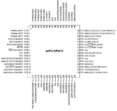
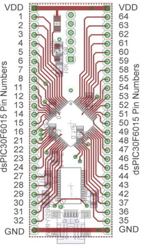
[image:1.612.80.525.214.635.2]Overview: In this lab we will become familiar with the dsPIC30F6015 and review programming a microcontroller to do some simple things. Most of the initial code will be given to you (see the class website), and you will have to modify the code as you go on. The dsPIC30F6015 has been mounted on a carrier board that allows us to communicate with a terminal (your laptop) via a USB cable. In what follows you will need to make reference to the pin out of the dsPIC30F6015 (shown in Figure 1) and the corresponding pins on the carrier (shown in Figure 2)
2
3
Part A (Copying the initial files)
Set up a new folder for this lab, and copy the files for this lab from the class website to this folder.
Part B (Downloading and installing MPLAB)
You will need to go to the website
https://www.microchip.com/pagehandler/en-us/family/mplabx/
and download the newest version of MPLABX. If you have an older of MPLAB it will probably work . It is probably easiest to download a zipped version and the unzip it. Do not intall any C compilers yet.
Part C (Downloading and installing MPLAB XC16 compiler)
You will need to go to the website
https://www.microchip.com/pagehandler/en-us/family/mplabx/
and download the MPLAB XC16 compiler for the dsPIC. We want to use the free version of the compiler.
Part D (Setting up Communications with Secure CRT)
In this step we will make sure all of our systems are working before we go on.
Connect the PICkit3 to the carrier board and your computer (the white arrow goes near the white spot on the carrier board, or on the pin closest to the actual dsPIC chip.)
Connect the separate communication cable to the carrieer board and your computer.
Connect power to the power board and toggle to on switch (the green LED should then be on)
4 We are going to want to be able to record and plot data, so we will be writing to the screen. In order to do this we will using Secure CRT because it is installed on your computer by default.
Go to ProgramsAll ProgramsSecureCRTSecureCRT6.7 (it’s ok if you don’t have 6.7). You should get a screen like this (although the list of Sessions will probably be shorter for you):
5 You should then get a screen that looks like this
Click on New Session
Choose Serial
from this menu, then click on Next
6 You will next get the following screen. You should already know which port to use (it may not be
COM5 on your computer). Select a Baud rate of 115200 and be sure everything is filled in as below. The click on Next.
7 Finally, you may get a screen like that below, and if you do then you need to select Connect.
Now you should have a terminal like that shown below
8
Part E (Putting it all together)
Now we are ready to start. Note that at some point in the following process you may need to let the system download firmware. Be sure you have selected the correct device (or it will do this twice).
Start MPLAB X IDE (not IPE)
Select File, then New Project (the screen should default to Microchip Embedded and Standalone Project)
Click on Next
In the Select Device section, select the following: Family: 16-bit DSCs (dsPIC30)
Device: dsPIC30F6015
Click on Next
In the Select Tool section, select PICkit3
Click on Next
In the Select Compiler section, select XC16
Click on Next
In the Select Project Name and Folder section, choose a name and project location.
Click on Finish
Make sure the file intro_dsPIC.cis in the Project folder. Right click on Source Files, then on Add Existing Item, then select intro_dcPIC.c
9 You should build (compile) the existing program, download it to the dsPIC, and run it. You should see a sequence of numbers on your screen (the secure CRT screen). These correspond to sample times.
If you see the following message
You are trying to change protected boot and secure memory. In order to do this you must select the "Boot, Secure and General Segments" option on the debug tool Secure Segment properties page.
Failed to program device
Then
Right Click on the Project Name (under Projects on the left panel) and select Properties
Under Categories in the left panel, click on PICkit3
Under Option categories at the top, select Secure Segment
On the right select Boot, Secure, and General Segments
Then select ok at the bottom.
Your program should now compile. Build (compile)
Download (to dsPIC)
10
Part F (Turning one LED on and off)
In this step we will make one LED turn on and off.
Locate pin 1 (RE5). Note that pin 1 is not the power supply pin! Connect a resistor and an LED to this pin as shown below:
We need to get this ready for output, so in the file intro_dsPIC.c, insert the lines (before the main loop)
TRISEbits.TRISE5 = 0;
You will see in the main loop we are writing all 1’s or all zeros to all of port E every other time interval. Compile your code and run it. Your LED should turn on and off regularly.
Part G (Running Two LEDs)
Connect your other LED to pin2 (RE6). Modify you code so the LED’s alternate (one goes on and the other off). Once this has been verified by your instructor (see the last page) , comment out the code that turns the LEDs on and off in the main code (do not delete it).
Part H (Utilizing PWM to run your LEDs)
We will now utilize the PWM function to drive the LED. Note that RE6 corresponds to PWM4L. In the routine pwm_init, change PWM_PDIS4L to PWM_PEN4L. This allows us to use this pin as a PWM signal. In the main code, uncomment the function call pwm_init();
Uncomment the code:
dutycycle = (unsigned int) ((double) AD_value)*scale; dutycyclereg = 4;
SetDCMCPWM( dutycyclereg, dutycycle, updatedisable);
11 Just before this segment of code, in the main loop, set AD_value = 512. Note that the AD_value is actually read from an input during an interrupt and we need to set it just before it is used.
Compile and run your code. A single LED should light (constantly).
Modify the values in AD_value from 0 to 512 to verify that the brightness of the LEDs changes as the dutycycle changes. Note that at some point the LED stops getting brighter, so don’t worry about that.
Part I (Reading in an A/D value)
Now we want to be able to connect a potentiometer so we can have a variable reference. The software is currently set up for A/D input on AN3/RB3. You will need to do the following things:
1) Connect the potentiometer as shown below 2) Set the appropriate TRIS bits for an input signal
3) Comment out the part of the code that sets the AD_value;
4) Modify the printf statement to allow you to also print out the dutycycle value.
Part J (Changing the dutycycle value by reading from the potentiometer)
Modify your code so the value of the dutycycle in the PWM routine is set by reading in a value from the potentiometer. As you turn the potentiometer the LED should change intensity. The value of the
dutycycle should be written to the SecureCRT screen, as well as the current time.
12
Part K (Implementing a stop button)
Finally we need to set an external stop button for our system. This is particularly important once we connect a motor to the system since just stopping MPLABX does not shut off the motor by itself, and we need to be able to directly shut off the motor. There are two parts to our stop button- an LED that shows the system is armed (and disarmed) and a switch that is connected to an external interrupt (interrupt 4 in this case). Connect an LED and the switch as shown in the following figure:
Note that the interrupt is at a high voltage unless the switch is pushed. You should wire this so the switch is easily accessable since you will need to use it regularly in subsequent labs. Finally you need to uncomment the following line of code that initialize the interrupt routine
Init_INT4();
13