Code Generation with “Visual Modeller”
Patrick Fillatre
Abstract
“Visual Modeller” is a CASE tool that permits end-users to model business processes, using the associated method “Visual Modelling”. It is also able to generate the database and a “front-end” application from this model. Although this generation looks like an integrated process to the user, an intermediary step exists. From the model of the business process, “Visual Modeller” first builds a model of the application that will be generated (ie a model of the future system), and then from this model, generates the database and the application.
Summary
1. The code generation process in “Visual Modeller” ...4
1.1. First step: building a generic application ...4
1.2. Separating different areas in the generic application ...5
1.3. The generation of code ...10
1.4. The user-interface of the generation of code in “Visual Modeller” ...12
1.5. State of the development...13
2. The generic application ...14
2.1. Objects of the generic application...14
2.2. Database objects ...16
2.3. Interface objects...18
2.4. Communications in the generic application ...20
3. Models for the generic application ...21
3.1. Introduction ...21
3.2. The generic application...21
3.3. The business object...22
3.4. The database object ...23
3.5. The relational database object ...23
3.6. The interface object ...24
4. The generation of code...25
4.1. What strategy to access to the database ...25
4.2. More details on strategies used to implement the generic objects ...27
4.3. Implementation of the “naming operation” in the automata...29
4.4. The ancestor of all the automata of “Visual Modeller”...30
4.5. The automaton generating the code for the business objects ...32
4.6. The automaton generating the code for the database ...37
5. Appendix...46
5.1. The functional model of the generation of code in “Visual Modeller” ...46
5.2. The project plan to develop the generation of code ...47
1. The code generation process in “Visual Modeller”
1.1. First step: building a generic application
1.1.1. What is a generic application
“Visual Modeller” does not directly generate an application in the target development language and system.
First it builds a model of the application from the business process model. This model of the application is called a “generic application” because it is greatly independent of the implementation environment: the environment system (also called the operating system), the computer language or the “Database Management System” (DBMS) that will be used for the implementation do not need to be specified. Only the configuration of the database(s) has to be specified: today it only means the type of the database (relational, for example).
Second, the definitive application and the database are generated from this generic application.
1.1.2. Why a generic application
1.1.2.1. Adaptability from the business process model:
The method carried by “Visual Modeller” brings the particularity to be user-centred. It must support a group of non-experts (e.g. end-users) specifying a model of a business process (which is not a model of a system) in an intuitive, incremental and iterative way. In particular:
• it avoids “systems” abstractions; it rather uses concrete concepts that the users are familiar with (as persons, organisations, documents)
• it supports unstructured model development
• it permits incomplete or incoherent or inconsistent representation of the business process it models
1.1.2.2. A better approach of the design of the application:
Building first a generic application, “Visual Modeller” can model the future system, that is the application it will generate, using the more powerful concepts, even if they are not present in the implementation environment. The characteristics of the generic environment are selected for:
• their power of representation
• their portability in multiple environments
Where “portability in multiple environments” of a concept means, the capability to implement what the concept represents when the code is generated in various environments. Although, this does not mean this concept must be present in all those environments: for example the “object-oriented” language “C++” is a pre-compiler of “C”, applications exist in “MSDOS” environment, for text mode display, with “graphical look-like” user-interface...
1.1.2.3. A better adaptability to implementation in multiple environments:
All the expertise required to design the application is applied to the generic application. The problems we will encounter to adapt “Visual Modeller” to generate some code for a new environment is only an implementation problem. We do not need to study a new design for the application, and generating some code with “Visual Modeller” for a new environment should be easier.
1.1.3. The characteristics of the generic application
As the generic application is built in a generic environment, it assumes some characteristics upon it. Here is the summary of the choices kept for the representation of the generic application:
• it is independent of the implementation environment, except for the configuration of the database (because it implies some constraints on the design of the database)
• different and separated domains, areas compose the generic application (for example, we
separate the domain of the application and the user-interface in the generic application)
• its definition is object-oriented
• the controls within the generic application are managed by events and message sending
• its user-interface is an interactive graphical user interface
• it is an MDI application (Multiple Document Interface application)
1.2. Separating different areas in the generic application
1.2.1. Why separated areas in the generic application
We will in particular, separate the domain of the application, that means the concepts of the business
process, from the other concepts concerning the treatments (functions) proposed by the application, the
presentation of the information, the database management. Each of these categories of concepts serves a specific purpose in a specific domain, with specific evolution and constraints. Each one has a different
cycle of life, the domain of the application being normally the more stable.
In the generic application, as it exists today, we separate the management of:
• the business process
• the user-interface
• the database
As the representation of the generic application is object-oriented, each of these areas in the generic application is associated to a specific type of object, respectively:
• the business objects
• the interface objects
• the database objects
The interface objects and the database objects are technology objects. That is not the case of the
business object: they are the objects of the business process (the domain of the application), they
correspond to the objects of the “real-world” in some litterature (see OOA/OOD “Object-Oriented
Analysis / Object-Oriented Design”, Coad and Yourdon, 1991).
Separating the model of the application in different areas is a design principle, but we also apply this separation in the process of the generation of code, reducing its complexity.
The advantages are:
• separating problems of different nature
• preserving the objects of the business process model from alterations due only to the current state of the art of the technology
• cutting down the complexity of the generation of code
• facilitating an iterative and incremental development of “Visual Modeller”
• facilitating group development on “Visual Modeller”
Remark: today, the activities are not represented in our models of the business processes.
still maintains the separation of the domain of the application from the other domains: the user-interface, the functions of the application (the activities), the database management.
1.2.2. The domain of the application
The domain of the application is the business process. In the generic application, it is represented using the business objects. A business object in the generic application corresponds to the definition of a business object given by the OMG BOMSIG (“Object Management Group” “Business Object
Management Special Interest Group” - Minutes of the Berlin Meeting, BOMSIG, OMG, Document Number 94-5-1, April 1994):
“A business object represents a thing active in the business domain including its business name, attributes, behaviour, relationships and constraints. It represents a real-world concept.”
A business object could also be seen as an object of the “real-world”. They are created directly from the model of the business process, even if “Visual Modeller” can then, optimise this hierarchy of business objects in the model of the system (ie. the generic application).
1.2.3. The database management
In the generic application, the management of the database is the affair of the database objects. Each persistent business object is associated to a database object, which:
• represents its image in the database
• offers some services of the database management (loading, updating, refreshing)
The database objects are built by “Visual Modeller” from the business objects of the generic application.
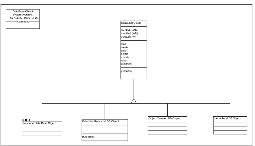
As the database objects are technology objects, they reflect the constraints due to the technology used for the database management. In the same time, one of their role is to hide this constraints to the
business objects. That is the reason, we produce the following hierarchy of database objects in the
DataBase Object
created (Y/N) modified (Y/N) deleted (Y/N)
load create save delete update refresh {abstract}
persistent
Extended Relational DB Object
persistent Relational Data Base Object
Object Oriented DB Object DataBase Object
System Architect Thu Aug 22, 1996 14:23
Comment
Hierarchical DB Object
Only one type of database will be managed with the first version of “Visual Modeller”: the relational database, as they are the reference type of database actually used on the market. By consequence, in the prototype we did the amalgam between the database object and the relational database object. That is what we will do from now in this document, in order to be concise.
The relational database is in the same time a good example of the problems we can encounter in linking an object-oriented representation with a non object-oriented database. The power of representation of a relational database is limited: the types of the fields (e.g. the attributes of a table in a relational database) are very limited: they are only atomic types. By consequence, an object can only be represented directly in a relational table if all its attributes have an atomic type which corresponds to a field possible type. Furthermore, the inheritance principle is unknown in relational databases. By consequence, more than one table can be necessary to represent a business object. Many strategies can be considered to store a super-class, all with advantages and disadvantages. More generally, that means that, depending on the constraints due to the configuration of the database, the structure of the
database is not necessarily a mirror of the structure of the persistent business object. This is
reflected by the following rules used by “Visual Modeller”:
• a business object can be represented by a hierarchy of database objects
• a database object can be a container of other database objects
• a database object, is not necessarily associated to a business object
• a persistent business object is associated with one database object
directly or indirectly as the hierarchy of the database objects can have as many levels as needed. A database object cooperates with the database objects of its sub-hierarchy to provide its services. Using the database objects, we do not need to transpose the representation limits of the database, to the representation of the business objects.
The notion of a database object is used to:
• manage the link between a business object and its image in the database
• hide the rules and the constraints implied by the configuration of the DBMS chosen for implementation, from the business object
• hide from the business object , its representation in the database
• handle the updates from or to the DBMS (Database Management System).
As we can see, the set of the database objects represents in the same time the structure of the database. The role of the database objects in the generic application is by consequence, dual as they represent:
• the link between the business objects and the database
• the model of the database
1.2.4. The user-interface
The user-interface of the generic application is an interactive GUI (Graphical User Interface), with an MDI (Multiple Document Interface). Its representation in the generic application is object-oriented. In the generic application, the objects used to represent it are the interface objects. They are technology
objects.
Each interface object represents a type of window of the user-interface, or a component of one of these windows. It can be linked to one of the business objects of the generic application and indirectly, to the business objects associated to it. This allow us to separate in the generic application the user-interface and the domain of the application.
The layer oriented models for the design of user-interface describe the tasks of the user from an abstract level to more and more concrete levels.
The task oriented models for the design of user-interface start from a formal description of the tasks.
The action oriented models for the design of user-interface suppose that the user interacts with the system via the mental representation he has of the system. The task process is considered as a process of execution and evaluation.
The control of the user-interface is action oriented. As the activities are not modeled today, the actions offered by the user-interface are predefined in “Visual Modeller”. The generated application offers the following services (actions):
• modifying objects
• deleting objects
• creating objects
• accessing from one object, to its associated objects
The interface objects are built by “Visual Modeller” from the business objects of the generic application. By consequence, the users do not need to build a dialogue specification. This is an advantage as our objectives are that the end-users must be able to be the main actors of the development process, from modelling themselves the business process, to the generation of the application.
Furthermore, linking directly the representation of the information in the user-interface to the concepts of the business process (the business objects), we can suppose a good correspondence between:
• the user’s mental representation of the domain (if he knows the business process model!?)
• the information presented in the interface
This can an advantage for the goal of getting an intuitive user-interface. Although, we need to study more in detail, how the activities of the business process will be presented in the application.
1.3. The generation of code
1.3.1. Languages used to generate the code in “Visual Modeller”
The generation of code is processed from the generic application. Each area of the generic application provides a language for the generation of code.
As we aim to be able to adapt “Visual Modeller” to different implementation environments, these languages have been designed as extensible languages: each of these languages provides a basic
language which permits:
• to access all the useful information contained in the generic application
• to navigate through this information
For each supported implementation environment, an extension of the basic language is specified outside of “Visual Modeller”, using this basic language, contained in “Visual Modeller”, to specify the extension.
1.3.2. Generation of code is a two steps process
The generation of code is processed by the automata in two steps. The automata (one for each language) could execute concurrently each step, but all these automata must have finished one step before one can start the next step. This constraint allows cooperation between the different types of objects in the application. The steps of the generation of code process are the following:
• first, the automata give an implementation name to the objects of the generic application they manage, and to their components (their attributes, their methods): we will call this step, the naming
operation.
• second, they generate the code for the implementation
1.3.3. The extensible language supported by the automata
Each automaton provides an alphabet composed of words which are associated to a predefined action that can return a result. These words can be classified in three sets:
• the iterators go through the structure of the object of the generic application managed by the automaton, updating the current local views on these objects. They point to the next item (an object or a component of an object), returning a boolean value, true when the next item has been found
• accessors which write in the automaton buffer information about the item currently pointed by the
local view
• the actions execute predefined actions, services offered by the automata
• the procedures which are expressions defined using the previous words
The actions offered by the automata are:
• “read” which writes a string of characters in the automaton buffer
• “makeFile” which creates a text file, closing the previously opened file if necessary
• “closeFile” which closes the opened text file
• “writeCode” which writes the value of the automaton buffer in the created text file
• “writeProject” which writes in the project file (known as the MAKE file for C programmers) the value of the automaton buffer
The automaton provides two control structures:
• if( < iterators > ) < word >
• while( < iterators > ) < word >
procedure : expression + suite
expression : if( iterator ) item expression : while( iterator ) item expression : item
item : procedure
item : word
word : action word : accessor
suite : { empty }
suite : expression + suite
action : read action : makeFile action : closeFile action : writeCode action : writeProject
The commands “iterator” and “accessor” offered by “Visual Modeller” are different for each automata, as each provides access to a specific range of information about the generic application.
1.3.4. Adapting the language to a specified implementation environment
All these words provide a grammar which allow “procedures” to written in the language used to generate the code. We decide now that these procedures must be regular on the left. This brings us determinism and by consequence, high performance in the speed of generation of code.
As the grammar is very limited and simple, it is well designed for a visual programming of the
procedure words of the automata. Only these kind of words are specific to an implementation
environment, the others are natively provided by “Visual Modeller” as the basis of the language. For each automaton, the procedure words are declared in a data file.
By consequence “Visual Modeller” is well adapted to generate some code for different environments. To be able to generate some code for a new environment, we only need to be able to:
• provide the information on this environment required for the naming operation
1.4. The user-interface of the generation of code in “Visual
Modeller”
In “Visual Modeller”, the user asks for the generation of an application from the model of a business process. He has to specify the target environment, development language, database and DBMS (for example, Microsoft Windows 95, Microsoft Visual Basic, the localisation of the database and Oracle
DBMS). Then the generic application is generated, and from this generic application, the database is
updated or created, and the code for the generated application is produced.
The user does not see these different steps of the generation. During the code generation, no intervention is required from the user. If the specifications in the business process model are incomplete or incoherent, the generated application will be incomplete or incoherent or some default options will be automatically chosen by the tool. So it is not necessary to develop an interface for the code generation!
The generation of the generic application includes three steps:
1. the business objects are generated from the business process model, using a set of “business objects generation rules”
2. from the business objects, the generation of the interface objects and the generation of the
database objects (including the design of the database) are realised independently, each one
with its proper set of rules (respectively the “interface objects generation rules” and the “database management rules”)
3. the translation of the generic application in the specified environment with the specified tools (development language, DBMS...). This step is detailed by the documents “Database Implementation” and “Business Object Implementation”.
1.5. State of the development
1.5.1. The version of December of 1996
A first version of “Visual Modeller” for the generation of the generic application and for the generation of code has been produced for the end of December of 1996 (see the project plan in appendix 2). It generates two applications from a model produced by “Visual Modelling”:
• an application able to create or to update the corresponding relational database
• a front-end application
Some limitations come that we do not now use all the modelling capabilities of the method. Thus the activities of the business process model are now unknown in the generic application. By consequence, the functions provided by the generated “front-end” application are limited: this “front end” application offers the users an interface to access to the instances of the business objects defined in the generic application. These instances are stored in one relational database (the concept of multi-databases is not managed). The application offers the possibility to show, create, modify or delete some instances of these objects. The associations between these objects are used by the application to:
• verify the integrity constraints (for example, when an order is created, an existing customer must be associated to the order)
• offer access to the associated objects from a selected object in the interface (for example, from the window displaying a customer, the user can get the display of all its orders)
From the generic application, the following restrictions are also done:
• one relational database only will be considered: “Microsoft Access”
• one implementation language only will be used: “Microsoft Visual Basic”
• no optimisation has to be considered now
• we don’t need to manage the events for the system failures
• we will not use the notion of event type (consequently to previous assertion)
• the notion of pre-condition and post-condition are ignored
Although, only the link with Microsoft Access databases will be tested, “Visual Modeller” is already implemented for all the database linked with Microsoft Jet Database, a subset of the ODBC API (“Object Database Connectivity Application Programming Interface”). The standard language SQL (“Structured Query Language”) is used to
• create or update the database
• implement the queries to the database
For the prototype the procedure words will be directly implemented in the code of the automata. So we don’t need to define:
• an interface to enter them
1.5.2. The current development
Currently two students are extending “Visual Modeller” so that it can generate some code for:
• Delphi (a Borland RAD - “Rapid Application Development” - product) • Javascript and HTML (“Hyper-Text Meta-Language”), using Corbix
1.5.3. Future development
When the activity will be modeled, the application objects will be implemented. The states of the
business objects will be represented by the pre/post conditions, the actions of the business objects will
be used by the application objects.
Other improvements will be decided from the experiences got from the existing version of “Visual Modeller”.
2. The generic application
2.1. Objects of the generic application
2.1.1. Three types of objects
The generic application representation is object-oriented. But its objects are not necessarily implemented directly in the generated application: for example, if the implementation computer language used is not object-oriented, rules of the same kind of those used to translate C++ in C can be used, or input controls can be implemented directly in the user-interface instead of the business object (on the same way an inline function is implemented in C++).
The objects of the generic application are broken down into the following three types of objects (already described in the chapter 1):
• business objects
• database objects
• interface objects
The generic application will itself be represented as an empty, non persistent business object. All the
not dependent business objects (all those which are not a part of another object, unlike the object “order line” existing only if it is associated to an object “order”, although it is not represented as an aggregated
object) are associated to the “generic application” business object. Therefore, the generic application has a representation of itself, that it can manipulate. Thus, this choice allows a reflexive representation
Note that it is disputable to represent the generic application as a business object, because the generic application is not part of the business process model.
2.1.2. Generation rules to create the generic application
The generation tool in “Visual Modeller” uses generation rules to specify how to create an object in the generic application, to update it or to aggregate it as part of another. There is a different set of generation rules for each of the three types of object of the generic application, and even a different set for each type of database. For the prototype, only the relational type of database can be selected.
The objective is to facilitate the process of construction of the generic application, which has to be an evolutive and incremental process. But for the first prototype, as for the automata, these rules are directly implemented in the code, although in a specific part of it.
2.1.3. Associations between the objects of the generic application
In the generic application, the associations between the objects of the generic application are described as a one direction association between two business objects. By consequence, two instances of association description are necessary to represent a dual way association. These two instances are linked.
In the generic application, the associations between the business objects are first created from the business process model. Then, while the generic application generates objects, it generates some association between them. The generation rules of the generic application can produce some modifications on these associations in the generic application. In particular, the generic application is able to determine how an association will be used (never, only in one way or in both ways). Different generation rules can be defined for different types of associations.
2.1.4. Actions and conditions
An action is a part of an object of the generic application: it corresponds to a method of the object. It is an ordered set of blocks of code (a set of instructions in the notation of C, C++, Pascal...) and action calls. The actions called can be actions of the same object or actions of other objects (in that case it corresponds to a message sent to another object).
A condition is an action which returns a boolean result. It allows us to verify if the object is in the predefined state described by the condition. Two conditions can be associated to one action. The action will not be executed if the result of the pre-condition is “false”. The action will not be validated if the result of the post-condition is “false”.
post-condition) is not difficult and will allow us to express explicitly some states for the related generic application object.
2.2. Database objects
2.2.1. The consequences of the dual role of the database objects
As shown in a previous paragraph (see 1.2.3. The database management) the database objects have a dual role in the generic application as they both represent:
• objects linking the persistent business objects with the database
• the model of the database
The attributes of a database object represent the fields of the table it is associated with. By consequence, the limits of the database apply on these technology objects.
2.2.2. The construction of a database object
2.2.2.1. General principle
The database objects are constructed in the generic application, from the business object, after they have been optimised. First one database object is constructed in the generic application for each persistent business and associated with this business object.
2.2.2.2. Constraints on the representation of the attributes of the business objects
But, the constraints of representation on the attributes of a database object are more restricting than the one upon the attributes of a business object; when the type of an attribute of a database object cannot be associated with a type of field in the database, this attribute becomes a “sub-database object”: this is a new database object contained by the previous database object, and not directly associated with any
business object.
This rule is sufficient to generate a correct model of database; but it presents the risk to split the database structure in too many tables. We propose the following rule to improve the structure of the database: if a “sub-database object” is contained by only one database object, and if one instance of its container can be associated with only one instance of the “sub-database object”, then the structure of the “sub-database object” is included in its container and the “sub-database object” does not exist any more.
2.2.2.3. When the database does not support the notion of inheritance
• a super-class that can be instanciated
• a virtual super-class that is never instanciated
In the generic application, we will make the distinction between:
• the super-class that are also used as persistent business object
• the other super-classes, considered like virtual super-classes
When a persistent business object inherits from a super-class which is also a persistent business object, we will treat this case as if, the first business object is always associated in a one to one relation with the second one. Attention, this means that when the first business object is loaded from, or updated in the database (updated meaning as well created, modified or deleted), the second one must be loaded or updated too.
In a first step, we will apply the same rule for the virtual super-class, except if only one business object directly inherits from it. In that case, the structure of the super-class business object is incorporated in the structure of the database object associated with the sub-class business object. Attention, this rule can be recursively applied if the sub-class business object is also a virtual super-class.
These solutions are simplistic. Perhaps this strategy does not provide the best performances, but it is simple, and in the same time we can expect a structure of the database:
• that does not contain too many tables
• where the structures of the tables do not contain too much fields
2.2.2.4. A relational database object must contain an identifier
One constraint due to the relational database is that each table description must contain an identifier field, which value can identify each line in this table. Therefore, when building the database objects in the generic application, “Visual Modeller” has to verify the existence of an identifier. In the definition of the business object a “unique value” constraint can be specified on some of their attributes. When the
relational database object is associated with a persistent business object, if the corresponding attribute
or set of attributes is present in the database object, it is therefore used as identifier in the relational table. If not, a supplementary attribute is created in the relational database object to play the role of the identifier. It is then invisible from the associated business object (if there is one) and the relational
2.2.2.5. Associations between persistent business objects and relational databases
The relational database can represent more than only a translation of the static structure of the persistent business object. In a relational database, the association between the persistent business object will generate foreign keys and integrity constraints in the tables of the database.
It would also be possible to generate embedded procedures in the relational database, but this will not be done in the first version of “Visual Modeller” because this is not a standard supported by all the
RDBMSs (“Relational Database Management System”). To implement the notion of embedded
procedures in relational databases, we will wait the stage of development in which “Visual Modeller” will be able to adapt itself, or will be able to generate applications that can adapt themselves, to the capabilities of the RDBMS(s) selected for the implementation.
2.3. Interface objects
2.3.1. A hierarchical structure of interface objects
An interface object is a component of the generic user-interface of the generic application. It describes all the visual components of the generic user-interface. As the generic user-interface is an MDI (the main window of the GUI of the application can contain different kind of child windows), the main window, the child windows and their components (the fields, the buttons...) are represented by interface objects.
Two types of interface objects are defined. These types are virtual (an interface object is always a specialisation of these virtual objects):
• a control which represents an elementary component in a window, like a field or a button
• a frame which represents a form (it means a main or a child window or a dialogue box) or a set of controls in a window (called an “inLine Display”)
2.3.2. Associations between the Interface and Business Objects
A frame represents:
• a set of controls (this set can be an entire form or an inline display - a component of a form)
• the association to one business object (the main associated business object) of all of these controls, and indirectly their association to the business objects associated to the business object linked with the frame.
2.3.3. “Inline display” objects
As a frame, an inline display is a type of interface object associated to one business object. It is typically used to display the “lines” of a “header” represented by the main business object associated to the form (for example the lines of an order in an “order form”).
If the business object associated to the form is the “application” business object (for example, in the main window), inline displays can be used in this form to give a list of the instances of an associated business object (for example the list of the customers).
The following will be implemented only as a rule for the generation of the generic application: “the business object associated to the frame must be itself associated to the main business object associated to the form containing the object display”. We will use “Visual Modeller” to verify this assertion.
2.3.4. “Field” objects
A field is a type of interface object directly contained in a frame (a “form” or an “inline display”). It displays information obtained from the main business object associated to this “frame”. It can be an output only field or an input (and output) field. For example, if we refer to Microsoft Window, the
labels, the fields, the combo-boxes, the list-boxes are represented by “field” objects in the generic
application.
To get the information, or to give it after an input, or to control the input, the field communicates with this business object by a message. So the displayed information can be one of the following:
• an attribute of this business object
• a “derived” attribute of this business object
• an information from an object associated to this business object
This communication by message with the associated business object implies that the generic application has to define in the business object methods to access its public attributes and methods to modify the value of some of them. When the code is generated, it is possible to improve the performances of the generated application by implementing “inline” (in the same meaning as in the C++ language) some of this methods.
2.4. Communications in the generic application
2.4.1. Messages
• the reference of the sender
• the reference of the receiver
• a request which is represented by the called method of the receiver (and the parameters)
An object can send a message to another type of object if they are associated (for example, a form can send a message to the business object which is the main business object associated to it).
The message corresponds to the notion of “message” used in the object-oriented programming languages. It is implemented by a call to an object method. It is represented by the association “calls” between two “actions” in the model.
2.4.2. Events
The event is one of the ways the objects of the application communicate together and the way they communicate with the system. An event is an asynchronous communication. It carries:
• the reference of the sender
• a type of event (not used in a first time)
• an information
The receiver is not defined in the event. Several objects can receive and handle the same event. The sender does not get a return value: it is a one way only communication. It does not need to know the receivers of the events he sends.
The events are useful to make the business objects, the user interface, the database management system and the environment system work together without being too closely dependent: each part doesn’t need to know how the others are implemented, it has only to notify them of some events. It is particularly useful to implement errors management.
During the code generation, depending on the characteristics of the selected development language, it is possible not to implement the notion of event and replace it by the sending of a message to the objects able to handle the sent event. Otherwise the events can be implemented for example with a queue of sent events and a handler of events in some objects to receive and handle them. Some events (usually the system error events) can also be implemented using the notion of exception.
2.4.3. Event Types
3. Models for the generic application
3.1. Introduction
These models have been generated with the CASE tool “System Architect” (a product of Popkin
Software & Systems Incorporated), using the OMT (“Object Modeling Technique”) method.
Note that all the objects (represented by a frame) marked with “o
•
o” are detailed in a sub-model.3.2. The generic application
Association description name origin cardinality destination cardinality ordered (Y/N) aggregation (Y/N) used in application (Y/N)
persistent DataBase Object created (Y/N) modified (Y/N) deleted (Y/N) load create save delete update refresh {abstract} Interface Object show {abstract} persistent Application Object name {abstract} persistent Action name persistent Event Type name persistent CODE GENERATION System Architect Tue Sep 03, 1996 16:11
Comment Condition boolean return persistent event information Block of Code
persistent Business Object Generation rule Application has dual
opposite direction assoc.
sends calls sender receiver has {ordered} 1+ has method associated with
destination of association origin of association
3.3. The business object
Business Object System Architect Mon Aug 26, 1996 17:43
Comment
Type of DataBase Attribute
Attribute of business object
property of component
Type of internal entity
Basic memory types
Component of model Business Object
inherit
super-class
sub-class
corresponds
property name
has generated from
model
generated from
model attribute name
has is type of
3.4. The database object
DataBase Object created (Y/N) modified (Y/N) deleted (Y/N) load create save delete update refresh {abstract} persistentExtended Relational DB Object
persistent Relational Data Base Object
Object Oriented DB Object DataBase Object
System Architect Thu Aug 22, 1996 14:23
Comment
Hierarchical DB Object
3.5. The relational database object
Association cardinality of Table 1 cardinality of Table 2 Relational Data Base Object
Type of DataBase Attribute Relational DataBase Table
Relational Data Base Object System Architect Thu Aug 22, 1996 16:16
Comment
Relational DataBase
Attribute link
Attribute of RDB
Model Set
Secondary Key Primary Key
link
attrib. of table 2
link
attrib. of table 1
[image:24.595.89.511.96.337.2]1+ details link Table 2 link Table 1 1+ has {ordered} has 1+ has {ordered} has generated from
root model set
contains is type of
type attribute name 1+ has access has part of container
3.6. The interface object
Form
open close {abstract} persistent Interface Object
show {abstract} persistent
Action name
persistent Interface Object
System Architect Thu Aug 29, 1996 13:18
Comment
Frame
{abstract} Control
{abstract}
Child Form modal (Y/N) inLine Display
persistent
button
persistent
Field
persistent
Menu Item
Main Form
Business Object
contains displays
associated object
contains
1+
has
contains
execute
command
sub-menu name has
4. The generation of code
4.1. What strategy to access to the database
4.1.1. Using a standard multi-platform solution
Many solutions are available to access a database from an application; among them, some can be considered as standards compatible with many DBMSs. By consequence, in the first version of “Visual Modeller”, even considering its limitations, one of these standard solutions has been preferred to a proprietary solution: the code generated in Microsoft Visual Basic does not use one of the proprietary solution offered by this language (as its dedicated controls or commands), neither the database is not created using the specific programming language VBA (“Microsoft Visual Basic for Applications”) provided by the Microsoft Access DBMS.
4.1.2. The ODBC API solution
One of the more powerful solution to access the DBMSs with Microsoft Windows applications is to use the Microsoft ODBC 2.0 API (“Open Database Connectivity Application Programming Interface”).
It is an extension to an industry standard (X/Open and SAG) which represents the core level of ODBC (corresponding to the1992 X/Open and SAG CLI). There are clear indications that cooperation among vendors and standards groups is producing a convergence of standards so that ODBC level API, the revised X/Open CLI and the forthcoming ANSI/ISO standard CLI (“Client Level Interface”) will be one and the same. Microsoft has committed to aligning ODBC 3.0 with the final ANSI/ISO standard for a call-level interface.
ODBC 2.0 specifications defines three levels of API conformance. The level one has become the
generally accepted standard by Microsoft and the ODBC community:
• core level corresponds to the 1992 X/Open and SAG CLI specifications (22 functions)
• level 1 add 16 functions to the core level
• level 2 add 17 functions to the level one (including SQLForeignKeys and SQLPrimaryKeys)
ODBC also provides functions (as other products do too, like the Intersolv’s QELIB library) that return
information about the drivers and the DBMSs features as the data types, the available SQL, the isolation levels, the cursor commit behaviour, the system catalogue information, and so on. By consequence, the
ODBC API allows the undertaking of a generic approach but also an adaptive approach, which
means that the ODBC API can be seen with an API view but also with a product-specific view.
Using an adaptive approach, the generated application means that is able to adapt at run-time to the capabilities of the ODBC driver for the used DBMS, offering by consequence higher performances. The generic approach is a minimalist, least-common-denominator strategy for writing portable applications.
The adaptive approach produces more powerful applications than the generic approach. But it is also more complex, requires a lot more work of development and is not relevant in the minimalist approach used for the development of our prototype. Although using the ODBC API in the prototype with a generic approach, offers us the possibility to evolve latter (and incrementally) to an adaptive approach.
4.1.3. Creating the database with the ODBC API
ODBC provides the ability to create tables, but the problem of creating and initialising databases is not
within the scope of the ODBC API. Some SQL dialects support CREATE DATABASE statement, but it is not a part of the ANSI SQL standard supported by ODBC. ODBC, the X/Open CLI, and the forthcoming ANSI CLI don’t attempt to include database administration as part of a data access call-level interface. Creating databases varies significantly from desktop to server and mainframe products.
4.1.4. The DAO solution
Microsoft proposes for Microsoft Windows a similar solution to the ODBC API: Microsoft DAO (“Data
Access Objects”).
DAO presents the following disadvantages compared to the ODBC API:
• the initial implementation of the object layer of DAO was a better solution for ODBC applications that used complex queries and large tables. Writing directly to ODBC API generally produced better performance for Visual Basic applications that used simple queries and small tables (see the article of Ken North “ Understanding ODBC and multidatabase APIs” in the March 1994 issue of DBMS that provides comparative performance data). Microsoft is wrapping the ODBC API in an object interface based on OLE objects, so future Data Access Objects will be available across applications, allowing ODBC API based applications to use DAO layer where it provides better performances.
• more DBMSs can be accessed by ODBC than by DAO.
Nevertheless, DAO is retained for the prototype because:
• DAO can coexist with the ODBC API in the same application. It is possible to evolve progressively
from a DAO application to an ODBC API application, even to mix both solution in the same application.
• the object layer of DAO provides a greater ease of use and transparency
• the more common DBMSs used on the market are accessible via DAO.
• DAO permits the creation or the update of a database
• as the ODBC API, DAO uses the SQL language to formulate queries to the DBMSs, which is a widely recognised standard
4.1.5. Implementing the database objects with an “OLE” technology
We could have implemented the database objects with an OLE technology. This would have simplified the generation of code for multiple programming environment, as the code for the database objects would have been the same for all the environments supporting OLE.
As “Visual Modeller” generates limited applications in its first version, we can suppose the code it generates could be completed by some developers. Also, we could wish to maintain this possibility in the next versions of “Visual Modeller”. As “Visual Modeller” is not designed to be used by high-level professionals in computer science, it is wished, at least now, to generate some code that can be easily extended. If we generate now some OLE objects, a third development environment (C++) will be necessary to be able to compile or update these objects.
By consequence, this solution has not been retained for the prototype.
4.2. More details on strategies used to implement the generic
objects
4.2.1. the aggregated objects
4.2.2. the methods of the objects in a non OOPL
When the programming language used for the implementation is not an OOPL (“Object-Oriented Programming Language”), the methods of the generic objects will be implemented as global functions or procedures. We will use a rule similar to the one used by a pre-compiler C++ to translate a method in a C function:
a method “m” of an object “o” will be implemented as a global function or procedure
of name “o_m” with a first parameter that will be a reference to an instance of an
object “o” (where “_” represents the linker character).
Parameters initialized in “Visual Modeller” define:
• the maximal length of the generated name (“o_m” in the example “o_m”)
• the maximal length of the prefix of the generated name (“o” in the example “o_m”)
• the linker character (“_” in the example “o_m”)
The prefix of the generated name can be truncated following the rules given in the paragraph about the “naming operation”. The full name is then truncated following this same rule.
The prefix “o” given for each object (also known as the short name of the object) is unique. It is not necessary but the generated sources will be more readable, being needed to calculate the short names only one time, allowing best performances, the only disadvantage being the space required to store the short name (in the generic objects).
4.2.3. the attributes of the objects
4.2.3.1. The name of the attribute must be unique within its scope
An attribute name needs only to be unique in its scope (that is the part of the application where it is visible). The name of an attribute must only be unique among the other attributes and methods of its object.
We decide that the name “a” of an attribute of an “object” “o” is unique in its form “o_a” (see the description of the naming rule for the methods in the above paragraph) for the global application and implemented in this form. It permits:
• to avoid resolution of name conflicts consecutively to the implementation of the inheritance
4.2.3.2. If the non OOPL provides user-defined types
Most programming languages permit to declare “user-defined” types which are composed of other types (like the structures “struct” in C, the “record” in Pascal, the “type” in Visual Basic). In that case an object will be implemented as one of these types. The components of the type correspond to the attributes of the object implemented as a user-defined type.
4.2.3.3. If the non OOPL does not provide user-defined types
In the non OOPL which do not provide user-defined types, the rules used to implement the names of the methods of the objects in a non OOPL are also used to implement the names of the attributes of the objects.
Each attribute of an implemented object is represented by a global variable when the type of the attribute allows that.
4.2.3.4. When an attribute cannot be implemented as a variable
When the type of an attribute does not permit to implement it as a variable, the rules to implement an object are applied to this attribute, and eventually the attributes of this attributes, and so on.
4.2.4. the inheritance between generic objects in a non OOPL
The inheritance needs to be translated too, when the implementation is done in a non object-oriented programming language. We use the following rules:
The attributes of its super classes are duplicated in the derived object.
A method “m” of an object calls the method “m” of its super-class at the end of its
personal code if it does not override it.
We must say that with this strategy, we must translate the reference to the virtual object too. Late
binding (that is determining the class of an object at run-time) is still possible if we implement the class
4.3. Implementation of the “naming operation” in the
automata
The rules to build a valid name of variable, type, function or method (...) are dependent of the used programming language. By consequence, before processing the naming operation, an automaton must get some information about the implementation language:
• is it object-oriented?
• has it the notion of user-defined compound types of data?
• what is the maximal length of the name of a variable?
• is the name of a variable case sensitive?
• what character (we call it the linker character) must be used to assemble two items in one name?
• what is the list of the forbidden characters when you name a variable, a function or a type?
An implemented name is built from the corresponding name used in the generic application. First, the forbidden characters must be filtered. Then we will assume the following rule, that is true in most of the programming language: a name must begin by an alphabetic character (ie. from “a” to “z”, or from “A” to “Z”) or by an underscore character. Then if the used programming language is not case sensitive, the proposed name is converted to lowercase...
But the main problem remains for the last step: we must ensure that the name we will use for the implementation is unique in the part of the application where it is visible. At a first step, we will not manage this notion of limited visibility in the application: anyway, we need a mechanism to construct a unique name within an area. So, it is simpler to define that area as the entire application, and although we believe managing several areas of visibility, it does not bring significant advantages.
To be able to build unique names and to be able to build names that verify the constraints of the implementation language upon their maximal length, we use a truncating mechanism: an implemented name is built from the corresponding name in the generic application. Its prefix is the generic name truncated to the maximal length allowed by the implementation language minus the length of its suffix. This suffix is the linker character followed by a number automatically incremented each time this suffix is used for a new name. In fact, this method is similar to the one used by Microsoft Windows 95 to build a MsDos file name from a long file name, using “~” as linker character.
the length of the name of the methods, and eventually of the attributes of the objects, will be shortened so that the composed name remains within the maximal length permitted by the programming language.
4.4. The ancestor of all the automata of “Visual Modeller”
The class “GDAutomaton” is the description of a virtual automaton in “Visual Modeller”. All the automata in “Visual Modeller” inherit from it. Seen from “Visual Modeller”, all the automata are activated as a “GDAutomaton” object, without consideration for what they are implementing.
The method “getExtensionLg” does not exist in this version, issued from the prototype of “Visual Modeller”. Its role will be to read the extension of the language for the generation of code by the automaton. Waiting for this solution, in the prototype, the procedures to extend the language provided by “Visual Modeller” to generate the code are directly implemented in the automata derived from “GDAutomata”. By convention, the name of the methods implementing a procedure begin with
“decl”.
Note that the methods which name begins by:
• “setFirst” are accessors
• “getNext” are iterators
Declaration of the class “GDAutomaton” extracted from the source file “PSeudoGDModel.h”
class GDAutomaton: public CObject { public:
CString Title; // title of the automaton protected:
GDModel* GenApplDatas; // pointer to the generic application datas CFile implemFile; // implementation file
int impFileStatus; // status of the implementation file (opened = 1) int objNameMaxLen; // max length of object name as “ObjN_AttribN" int varNameMaxLen; // max length of a name of variable, type, function BOOL isOOL; // is the implementation language Object Oriented ? BOOL caseSensitiveNames; // is naming (variables, types...) case sensitive ? TCHAR separator; // separates the prefix and the serial nb in a name public:
GDAutomaton( CString myTitle = "", GDModel* model = NULL ); ~GDAutomaton();
virtual void buildImplementedObj() = 0; // build source for implementation of generic objects
void buildNamesForImplem(); // build the names for the implemented objects
void linkGenAppl( GDModel* model ); // link automaton and generic application virtual CString getObjectName() = 0; // current object name used for
implementation
virtual CString getAttribName() = 0; // current attribute name used for implementation
protected:
virtual BOOL getNextObject() = 0; // read the next object virtual BOOL getNextAttrib() = 0; // read the next attribute CString getMethodName( const CString genericName )
{ return GenApplDatas->getMethodName( genericName, this ); CString giveVarName( const CString proposal, // give name for variable
const CString prefix = "" );
CString givePrefixName( const CString proposal ); // give name for prefix
inline COrdServer& usedNames(); // return the list of the used names // create an empty file
int makeFile( const CString fileName, const CString extName ); int closeFile( ); // close the file opened with "makeFile" // method name used for implementation
}
void write( CString buffer ) // write buffer in implementation file { implemFile.Write( buffer, buffer.GetLength() );
} private:
// apply the 1st set of naming constraints void setNamingRules( CString proposedName );
// see "usedNames"
CString giveNewName( int maxLength, const CString proposal ); };
4.5. The automaton generating the code for the business
objects
4.5.1. The declaration of the automaton used for the prototype
The class “GDBOAutomaton” is used in “Visual Modeller” to instantiate the automaton that implements the business objects. In the prototype, it is dedicated to generate some code for the programming language Microsoft Visual Basic. But this is only a simplification used for the prototype. In the next versions of “Visual Modeller”, this automaton will be used to generate some code indifferently for any programming language (see the paragraph describing the virtual automaton “GDAutomaton” for more details).
Declaration of the class “GDBOAutomaton” extracted from the source file “Automata.h”
class GDBOAutomaton: public GDAutomaton { public:
GDBOAutomaton( CString myTitle, GDModel* model = NULL ); ~GDBOAutomaton();
void buildNamesForImplem(); // build the names for the implemented objects void buildImplementedObj(); // build the source to implement the BO // (where BO means business object) private:
// ... the iterators
void setFirstObject() { GenApplDatas->setFirstBusinessObject(); } void setFirstSupClass() { GenApplDatas->setFirstSupClass(); } void setFirstAttrib() { GenApplDatas->setFirstAttrib(); } void setFirstForeignK() { GenApplDatas->setFirstForeignK(); } void setFirstAssoc() { GenApplDatas->setFirstAssoc(); } void setFirstAssoAttr() { GenApplDatas->setFirstAssoAttr(); }
BOOL getNextObject() { return GenApplDatas->getNextBusinessObject(); } BOOL getNextSupClass() { return GenApplDatas->getNextSupClass(); } BOOL getNextAttrib() { return GenApplDatas->getNextAttrib(); } BOOL getNextForeignK() { return GenApplDatas->getNextForeignK(); } BOOL getNextAssoc() { return GenApplDatas->getNextAssoc(); } BOOL getNextAssoAttr() { return GenApplDatas->getNextAssoAttr(); } // ... the procedures, extension of the language for the generation of code // ... temporary methods for the prototype
void declClassModHdr(); // to declare the header of a class module in VB void declObject(); // to declare a BO
void declAttrib(); // to declare an attribute of a BO
void declAssocQry(); // to declare the query objects to associated BO void declOneInstance(); // to declare one instance of a BO
void declObjctMethod(); // to define the methods of a BO
void declQryMethod(); // to declare the query method to current assoc. void declGlobal(); // to declare the global variables, objects void declIniFromAssoc(); // to declare initialisation of attribute // associated object
void declResetValAttrib(); // to reset the value of an attribute to the // default value
void declNullAssocObj(); // to reset the result of a query about the // association
void declResAssocQry(); // to reinit the result of a query about the // association
};
4.5.2. An example of implementation of a business object with the prototype
4.5.2.1. The language in which the code is generated
The code to implement the business objects is generated in the programming language Microsoft Visual
Basic 4. This is not an OOPL (“Object-Oriented Programming Language”), but user-defined types
(composed of attributes of other types) can be defined. This language offers also an interesting feature: the class module that allows simulating some characteristics of an object-oriented programming language: each class module file allows the declaration of one object. This technique allows polymorphism, encapsulation, but does not permit the inheritance to be managed by Visual Basic 4.
In Microsoft Visual Basic a variable name:
• must begin with an alphabetic character
• can’t contain an embedded period or type declaration character (ie. “$” or “%”)
• must be unique within the same scope
• must be no longer than 255 characters
• is not case sensitive (written in lower case by convention)
4.5.2.2. Example of extension of the language to generate the code
by the implementation of the procedures. The name of the procedures are written in bold characters in the following example.
Notice the other automata extend the language provided by “Visual Modeller” for the generation of code in a quite similar manner.
Content of the source file “automata.cpp” implementing the automata in “Visual Modeller”
//--- // to declare a B.O.
void GDBOAutomaton::declObject() { CString buffer;
makeFile( "GenSource\\"+getObjectName(), ".CLS" );
if ( impFileStatus != OPENED ) return; // tested because uses "write"
declClassModHdr();
buffer = " Class Module of the Business Object '"+getObjectName()+"' ---\"\n\n";
write( buffer ); buffer = "\n\n"; write( buffer );
while ( getNextAttrib( ) ) declAttrib(); setFirstAssoc();
while ( getNextAssoc( ) ) declAssocQry();
buffer = "Dim MyDBObject As "+getDBObjectName()+"\n\n"; write( buffer );
declObjctMethod(); // declOneInstance();
closeFile(); }
//--- // to declare an attribute of a B.O.
void GDBOAutomaton::declAttrib() { CString buffer;
buffer = "Public "+getAttribName()+" As "+getAttribType()+"\n"; write( buffer );
}
//--- // to declare the queries to associated B.O.
void GDBOAutomaton::declAssocQry() { CString buffer;
buffer = "Public To"+getAssocObjName()+" As DcQuery\n"; write( buffer );
}
4.5.2.3. The code generated
The automaton GDBOAutomaton of the prototype generates a Visual Basic class module file:
• for each business object of the generic application
• for the object DcQuery, specific to the applications generated in Visual Basic
DcQuery object is used by the object implementing a business object, to send some queries to the
database concerning the instances of an associated business object. The DcQuery gets a Recordset as the result of this query, allowing the application to create the corresponding business objects in memory.
Content of the class module file “DcQuery.cls” generated in “Visual Basic 4”
VERSION 1.0 CLASS BEGIN
MultiUse = -1 'True END
Attribute VB_Name = "DcQuery" Attribute VB_Creatable = True Attribute VB_Exposed = True
Attribute VB_Description = " --- Class Module of the Request Object " ' The "dc" prefix is reserved to the class defined by default in ' the application.
Public Rc_QueryResult As Recordset
'Constructor
Public Sub Class_Initialize() End Sub
'Execute the request
Public Sub find(SQLStatmt As String)
Set Rc_QueryResult = Dbdatabase.OpenRecordset(SQLStatmt, dbOpenDynaset) End Sub
'Close the request
Public Sub dc_query_close() Rc_QueryResult.Close Rc_QueryResult = Nothing End Sub
'Return the number of records in the result Public Function count() As Integer
If Rc_QueryResult = Nothing Then RetVal = 0
Else
RetVal = Rc_QueryResult.count End If
End Function
'Move on the first record of the result Public Sub MoveFirst()
Rc_QueryResult.MoveFirst End Sub
'Move on the next record of the result Public Sub MoveNext()
Rc_QueryResult.MoveNext End Sub
Private Sub Class_Terminate() On Error Resume Next Rc_QueryResult.Close
End Sub
Here follows an example of business object implemented by the prototype: it is an object “customer” associated with zero to many objects “order”.
Content of the class module file “ObBOCustomer.cls” generated in “Visual Basic 4”
VERSION 1.0 CLASS BEGIN
MultiUse = -1 'True END
Attribute VB_Name = "ObCustomer" Attribute VB_Creatable = True Attribute VB_Exposed = True
Attribute VB_Description = " --- Class Module of the Business Object 'ObCustomer' ---"
Public AtCust_Id As String Public AtName As String Public AtCompany As String Public AtCategory As Integer Public ToObOrder As DcQuery Dim MyDBObject As ObDBCustomer
'constructor of "ObCustomer" Public Sub Class_Initialize()
resetAttrib
Set MyDBObject = New ObDBCustomer End Sub
'destructor of "ObCustomer" Public Sub Class_Terminate()
Set ToObOrder = Nothing Set MyDBObject = Nothing End Sub
'to initialize the attributes of "ObCustomer" from the database. Public Function load( ) As Boolean
load = MyDbObject.load( Me ) End Function
'to save "ObCustomer" in the database. Public Sub save( )
MyDbObject.save Me End Sub
'to update "ObCustomer" in the database. Public Sub update( )
MyDbObject.update Me End Sub
'to delete "ObCustomer" from the database. Public Sub delete( )
'to load "ObCustomer" in the database from the result of a query. Public Function loadFrQuery( ArResultQuery As Recordset )
loadFrQuery = MyDbObject.loadFrQuery( ArResultQuery, Me ) End Function
'reset the value of the attributes Public Sub resetAttrib()
AtCust_Id = "" AtName = "" AtCompany = "" AtCategory = 0
Set ToObOrder = Nothing Set ToObOrder = New DcQuery End Sub
'query on the association with "ObOrder" Public Sub qryToObOrder
Dim SQLQuery As String
SQLQuery = "SELECT * FROM ObDBOrder WHERE "
SQLQuery = SQLQuery + "Cust_Id_1 = "+Chr(34)+AtCust_Id+Chr(34) ToObOrder.find SQLQuery
End Sub
'initialise an associated object from the query on "ObOrder" Public Sub IniMy_ObOrder( ArAssocObj As ObOrder )
ArAssocObj.loadFrQuery ToObOrder.Rc_QueryResult End Sub
4.6. The automaton generating the code for the database
4.6.1. The declaration of the automaton used for the prototype
The class “GDRDBaseAutomaton” is used in “Visual Modeller” to instantiate the automaton that generates the application whose role is to create or update the database.
Declaration of the class “GDRDBaseAutomaton” extracted from the source file “Automata.h”
<