Design and modelling of permanent magnet fault current
limiter For electrical power applications
AL-NAEMI, Faris, ISSA, Walid <http://orcid.org/0000-0001-9450-5197>,
RAMADAN, Asmaiel and HALL, Jeremy
Available from Sheffield Hallam University Research Archive (SHURA) at:
http://shura.shu.ac.uk/22868/
This document is the author deposited version. You are advised to consult the
publisher's version if you wish to cite from it.
Published version
AL-NAEMI, Faris, ISSA, Walid, RAMADAN, Asmaiel and HALL, Jeremy (2018).
Design and modelling of permanent magnet fault current limiter For electrical power
applications. In: 53rd International Universities Power Engineering Conference 2018,
Glasgow, 4 - 7 September 2018.
Copyright and re-use policy
See http://shura.shu.ac.uk/information.html
978-1-5386-2910-9/18/$31.00 ©2018 Crown1
Design and Modelling of Permanent Magnet Fault
Current Limiter For Electrical Power Applications
Faris Al-naemi Electrical Engineering DEPT.
Sheffield Hallam University Sheffield, U.K [email protected]
Walid Issa
Electrical Engineering DEPT. Sheffield Hallam University
Sheffield, U.K [email protected]
Asmaiel Ramadan Electrical Engineering DEPT
Sheffield Hallam University Sheffield, U.K [email protected]
Jeremy Hall Electrical Engineering DEPT
Cardiff University Cardiff, U.K. [email protected]
Abstract- As the electrical power grids are extending in capacity with connection of distributed generations, the fault current level is increasing and approaching the capacity limits of the circuit breakers. In this paper, a saturated inductor fault current limiter (FCL) based on permanent magnet biasing has been developed to overcome the inherent disadvantages associated with many previous technologies such as superconducting based techniques. A 3D Finite Element Modeling (FEM) is used to develop and validate the proposed design and compared it with air-cored inductor. A lab-scale prototype was built to verify the design. Furthermore, a scaled up model which could be introduced to 11 kV network is introduced and its electromagnetic performance is evaluated.
Keywords—fault current limiter, permanent magnet, magnetic field analysis, Inductance calculations, finite element method, transient modeling, permanent magnet demagnetization.
I. INTRODUCTION
The increase of the power loads demand and the expanding and integration of more renewable energy generation will consequently have an impact on the level of fault currents [1]. The increase in fault current may exceed the current capabilities of circuit breakers risking the power system infrastructure and reliability. For future power systems to cater for these fundamental changes, changing the whole infrastructure with higher ratings is required. However, such approach is not cost effective and feasible. Several solutions and techniques for limiting fault currents have been proposed in the past such as upgrading fast circuit breakers, system reconfiguration, installing transformers with higher impedance, current limiting fuses, air-core reactors, etc. [1]-[3]. However, those methods were practically limited due to high estimated costs, lack of system security and reliability.
There are recent techniques to address this issue by limiting the fault current itself such as the introduction of superconductors fault current limiters and solid-state fault current limiters, but they still fall behind in addressing some concerns such as the running cost, installation cost, maintenance cost and reliability. Among the promising techniques to limit the fault current is the magnetically saturated reactor in which the biasing is achieved by a permanent magnet assembly. Hence a permanent magnet fault current limiter (PMFCL) has recently attracted a lot of interests of researchers and scientists [4], [5]. The PMFCL is a non-linear impedance device connected in series in an electrical power system. Ideally, it has low impedance in normal operation which rises almost instantaneously to a higher value
under fault conditions, back instantaneously to low impedance value after the fault clearance with no resetting procedure.
II. PMFCLMAGNETIC CIRCUIT
In principle, PMFCL devices are mainly consist of soft magnetic core or cores which are biased to saturation by a permanent magnet excitation systems (PM), and coils carries the ac current wound around such cores. In the design of such devices an attempt of utilizing analytical approach was reported in [5]. In such approach the active components of the magnetic circuit were linearized as shown in figure 1. Using Amper's circuital law and empirical factors to cater for magnetic saturation, the PM excitation system could be estimated to ensure a reasonable level of saturation to the soft magnetic cores. In normal conditions they are operating around point P as in figure 1. At fault conditions, the ac fault current brings the core back to point S introducing higher core permeability and hence higher inductance. The ac operating conditions of such PMFCL could be estimated from evaluating the corresponding values of Hs and Hu. The analytical
[image:2.612.317.553.457.582.2]approach fall short of calculating the core saturation depth of such devices which is a crucial design parameter [7][8].
Fig. 1. Linearized B-H characteristics of active materials in PMFCL [5]
2 component of a leakage flux along the third axise of the magnetic circuit design; which is assumed to be constant in 2D FEM. Hence the 3D FEM design tool is the accurate approach.
In this paper, the design methodology of this class of devices is presented, analyzed using 3D FEM tool and verified by a small scale lab prototype. Moreover, the main electromagnetic operating characteristics of a full scale PMFCL design are presented and discussed which could be suitable candidate technique to address higher fault current in 11 kV distribution systems.
III. DESIGN METHOD
The main aspects of the design of PMFCL are the accurate calculations of the excitation system and the dynamic response of the device. The excitation system of a PMFCL should be addressed by the nonlinear 3D Magnetostatic solver with tight values of the newton tolerance and the conjugate gradient parameters. The FEM models should be solved with higher polynomial order of the potential in the mesh elements. In order to decrease the solution time, the polynomial order should be increased only in the areas of interest like the air region around the coils and core region. The B-H curve of the core material is a crucial parameter in the design, hence a measured characteristics of the core, where the magnetic field intensity (H) is extended into the saturation region, is an important input parameter to the design tool. The following design parameters of PMFCL could be obtained using the 3D-magnetostatic method:-
• Geometrical topology.
• The core saturation depth.
• Steady state operating mode.
• Operating limits at fault conditions.
• Demagnetization limit of the PMs.
The analysis of the dynamic response of such devices could be achieved using 3D nonlinear transient solver coupled to an electrical circuit model. It should be voltage driven model, where the operating current of such device in time domain is the evaluated parameter at each time step. It is comprehensive solver that requires higher computational time. The use of magnetic symmetry and boundary conditions cut the computational cost.
[image:3.612.316.548.93.253.2]IV. PROPOSED PMFCL DESIGN
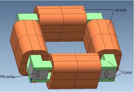
Fig 2 shows a proposed design for a PMFCL, the active components of the magnetic circuit are four rare-earth PMs, two soft magnetic cores and four ac coils. The PM poles are positioned in the corner between the two cores and they are placed in alternate polarity. The PMs should provide the required excitation to drive the cores into saturation and attending a flux density value of around 2.2T, such value of flux density depend entirely on the chosen soft magnetic material type for the core. Each of the ac coils is wound around the two cores so that it will act at fault condition irrespective of the fault occurrence in positive or negative half cycle of ac
current. The coils connections and number of turns will adapt the design for various operating current and fault levels.
Fig. 2. PMFCL proposed design
A. Prototype development
A small scale lab version of the proposed configuration was designed using 3D FEM magnetostatic and transient solvers to verify the operating concept and the calculations of the operating parameters. Another prototype of the same dimensions was built with non-magnetic materials (no cores and PMs). This is to compare the performance of the PMFCL against air-cored inductor design. Figure 3 shows the prototypes and Table 1 shows the details of the PMFCL.
The initial dimensions of the core and PMs was calculated using classical magnetic circuit theory [5], the optimum dimensions obtained using 3D FEM magnetostatic to ensure the core saturations depth of minimum flux density value of 2.1T. An operating current at steady state of 5A rms, and fault current of 30A rms has been selected.
(a) (b)
Fig. 3. the PMFCL prototype (a) & the air-cored prototype (b)
[image:3.612.311.571.482.596.2]3
Parameter Type or value
Iron core material M4 Iron core size (mm) 189 x 27 x 4
PM type Nd-Fe-B (N52) Permanent Magnet size (mm) 30 x 30 x 30
AC coil length along the core 99 mm
A.C coil No of turns 210 Supply voltage 90V RMS
[image:4.612.38.289.63.191.2]Frequency 50Hz
TABLE I. DETAILS OF THE PMFCL PROTOTYPE
B. Results
Fig 4 shows the flux density values of the PMFCL prototype model at the instant of 40A peak fault current. The figure shows the parts of the core that the fault current acts against the PM excitation direction; driving it back to lower flux density and hence higher inductance. The other parts of the core is where the current in the same direction as the PM excitation.
Fig. 4. FEM result PMFCL prototype core at the fault current of 40A peak,
The range of the operating current of the PMFCL could be evaluated by calculating the inductance of the device at a defined current value. The flux linkage method is used to calculate the inductance. At the postprocessing stage of an FEM solution flux linkage λ which is the total flux linking a coil of N number of turns ( λ=NΦ ) can be obtained as
λ =[λ(Ι)] Ι + λο (1)
where λo corresponds to a constant flux linkage through
the coil due to the presence of PM.
Figure 5, shows the calculated flux linkages of all the coils for the PMFCL prototype. The profile shows three regions of operation. The steady state region up to 8A where the device is saturated and offer low impedance, the fault region between 8A to 30A where the device offer higher impedance due to higher core permeability and the region over 30A where the
[image:4.612.315.532.95.224.2]core back to saturation due higher ac coils current driving the core back in opposite direction to the PM field.
Fig. 5. calculated flux linkage for all the coils in PMFCL prototy
The inductance of the device could be obtained by performing a couple of magnetostatic solvers at different currents in order to obtain λ1 and λ2 corresponding to I1 and I2
then:
[image:4.612.44.286.337.449.2]L = ∆λ/∆I (2)
[image:4.612.315.539.407.548.2]Fig 6 shows the calculated and the measured absolute inductance of the PMFCL prototype. It shows good correlation between measured and calculated results. Such characteristic is quite useful to determine the operating current range of such device and it is essential to determine the parameters of the coupled electrical circuit that be used in the transient model.
Fig. 6. calculated and measured inductance of the PMFCL prototype.
4 the model was used. Figure 7 shows the mesh of the FEM model and the electrical circuit parameters.
Fig. 7. 3D mesh and the coupled electrical circuit models
An experimental set up to test the PMFCL and the air-cored prototypes was established; it consists of variable supply voltage, variable load, switch, and current-measuring equipment. Figure 8 and figure 9 show the measured and the calculated results where a sufficient agreement between measured and calculated characteristics was established.
Fig. 8. Figure 8 Calculated dynamic response of the prototypes
Fig. 9. Figure 9 Measured dynamic response of the prototypes
C. Power grid desig
A design and modelling of 11 kV PMFCL for power grid was carried out. The magnetic circuit of the design was chosen to match the one of the prototype shown in figure 2. The details of the main parts, materials types and the coils are in Table-2
Parameter Type or value
Iron core material M4 Iron core dimensions (3 x 0.3 x 0.008) m
PM type Nd-Fe-B (N52)
PM coercivity Hc= -8.68x10⁵
A/m
PM
dimensions-perpole (1x0.3x0.7) m
No of poles 4
A.C coils cross
sectional area (1.026 x 0.31) m 2
A.C coils No of turns 40 AC coil length 0.8 m
TABLE II. DETAILS OF THE PMFCL PROTOTYPE
Figure 10 shows the 3D magnetostatic modelling results of the calculated differential inductance versus current. This figure shows, for the defined parameter, the operating current range of the PMFCL between 6kA to 10kA.
Fig. 10.calculated inductance of the PMFCL.
5
Fig. 11. Calculated dynamic response of the design
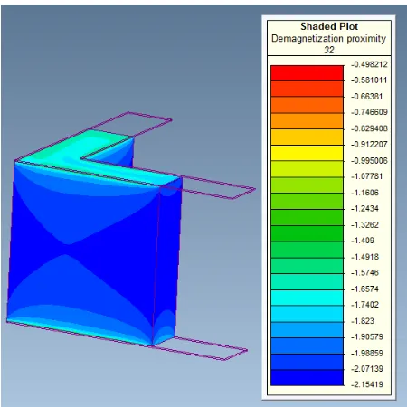
D. Modelling of PM DEMAGNETISATION
Under the high short circuit fault current values of 25 kA, the demagnetization effect of the PM poles in the design was investigated. This was achieved using the 3D magnetostatic solver where the ac current of 25 kA in the coils was defined. The demagnetization proximity of the PM poles or a region within the PM pole could be displayed in post processing stage of the FEM solution. Figure 12 shows the result of the PM pole demagnetization proximity modelling. The negative values in the figure indicate that the PM pole is still within the magnetization region. Only region of the pole with a positive value indicator could be subjected to demagnetization [9]. Hence the modelling results shows that the PM poles in the design could withstand much higher fault current values. This is mainly due to the topology design of the magnetic circuit where the fields from the ac coils are in perpendicular plain to the PM fields.
Fig. 12. Modelling of demagnetization effect of the PMFCL poles at 25 kA.
V. CONCLUSION
The PMFCL technology is promising alternative to address the ever increasing tendency of fault current in power network. Such devices could be designed and developed with the aid of 3DFEM design tool to determine the electromagnetic performance. The proposed design could be introduced to power distribution systems. The operating current could be tailored by adjusting the ac coils number of turns. The proposed design offered good demagnetisation capability of the PM poles. The cost of the PM materials is one of the challenging commercial issues for such design. However, proper choice of cost effective PM materials could overcome this challenge. The proposed design has been analysed, verified practically in limiting high fault current and compared with air-cored one.
8REFERENCES
[1] MORICONI, F., et al. (2010). Modelling and test validation of a 15kV 24MVA superconducting fault current limiter. In: Transmission and Distribution Conference and Exposition, 2010 IEEE PES, 1-6.
[2] POWER, AJ (1995). An overview of transmission fault current limiters. In: Fault Current Limiters - A Look at Tomorrow, IEE Colloquium on, 1/1-1/5.
[3] PUTRUS, G. A., JENKINS, N. and COOPER, C. B. (1995). A static fault current limiting and interrupting device. In: Fault Current Limiters - A Look at Tomorrow, IEE Colloquium on, 5/1-5/6.
[4] SANTRA, T., et al. (2009). Analysis of passive magnetic fault current limiter using wavelet transforms. In: Power Systems, 2009. ICPS '09. Internatioal.
[5] Liang Zou, et al. (2009). Study on the feasibility of developing high voltage and large capacity permanentmagnet-biased fault current limiter. In: Universities Power Engineering Conference (UPEC), 2009 Proceedings of the 44th International, 1-5.
[6] Liu, Hongshun, et al. (2012) Comparative study on the static and dynamic characteristics of four types of PMFCLs for large capacity applications. International Journal of Electrical Power & Energy Systems 34.1 (2012): 47-56.
[7] HALL, J. and CHEER, A. (2013). Fault current limiter surge protection device for the power grid based upon zero power consumption ceramic ferrite permanent magnets. In: Electricity Distribution (CIRED 2013), 22nd International Conference and Exhibition on, 1-4.
[8] Ramadan, Asmaiel, and Faris Alnaemi. (2017) Design and modelling techniques of permanent magnet fault current limiter. Energy Procedia 134: 616-625.
[9] Magnet user manual by Infolytica, www.infolytica.com.
[image:6.612.45.270.443.668.2]![Fig. 1. Linearized B-H characteristics of active materials in PMFCL [5]](https://thumb-us.123doks.com/thumbv2/123dok_us/678021.570537/2.612.317.553.457.582/fig-linearized-b-h-characteristics-active-materials-pmfcl.webp)