ORIGINAL RESEARCH
INTERVENTIONAL
Parent Artery Curvature Influences Inflow Zone Location of
Unruptured Sidewall Internal Carotid Artery Aneurysms
K. Futami, H. Sano, T. Kitabayashi, K. Misaki, M. Nakada, N. Uchiyama, and F. Ueda
ABSTRACT
BACKGROUND AND PURPOSE: Future aneurysmal behaviors or treatment outcomes of cerebral aneurysms may be related to the hemodynamics around the inflow zone. Here we investigated the influence of parent artery curvature on the inflow zone location of unruptured sidewall internal carotid artery aneurysms.
MATERIALS AND METHODS: In 32 aneurysms, the inflow zone location was decided by 4D flow MR imaging, and the radius of the parent artery curvature was measured in 2D on an en face image of the section plane corresponding to the aneurysm orifice.
RESULTS:The inflow zone was on the distal neck in 10 (group 1, 31.3%), on the lateral side in 19 (group 2, 59.4%), and on the proximal neck in 3 (group 3, 9.4%) aneurysms. The radius in group 1 was significantly larger than that in group 2 (8.3 mm [4.5 mm] versus 4.5 mm [1.9 mm]; median [interquartile range];P⬍.0001). All 7 aneurysms with a radius of⬎8.0 mm were in group 1. All 18 aneurysms with a radius of⬍6.0 mm were in group 2 or 3. In two group 3 aneurysms, the inflow zone was located in a part of the neck extending beyond the central axis of the parent artery.
CONCLUSIONS: The inflow zone locations of sidewall aneurysms can be influenced by the parent artery curvature evaluated in 2D on an en face image of the section plane corresponding to the aneurysm orifice.
ABBREVIATION:IQR⫽interquartile range
T
he hemodynamics around the inflow zone of cerebral aneu-rysms may be a principal cause of growth,1-4bleb formation resulting in rupture,1,2,5-8and regrowth following clipping sur-gery or endovascular coiling.9-13These sequelae are possibly re-lated to the increased wall shear stress on the aneurysmal wall surrounding the inflow zone.2-6,14Therefore, both identification of the exact location of the inflow zone and evaluation of the hemodynamics around this area may contribute to predicting fu-ture aneurysmal behaviors or obtaining good treatment out-comes.15Previous studies have estimated that neck width and geometric relationship between an aneurysm and the parent ar-tery are dominant factors in the determination of the inflow zone location.1,14,16-194D flow MR imaging based on time-resolved 3D cine phase-contrast MR imaging techniques was recently used to evaluate the
hemodynamics of cerebral aneurysms20-24and to identify the in-flow zone of cerebral aneurysms.15However, no previous studies have examined the correlation between the distribution of the inflow zone on the section plane corresponding to the aneurysm orifice and aneurysm morphology or the parent artery curvature in patient-specific imaging analysis, to our knowledge. Here we investigated the influence of morphologic factors or the parent artery curvature on the inflow zone location identified by using 4D flow MR imaging in unruptured sidewall ICA aneurysms.
MATERIALS AND METHODS
MaterialsThis study was approved by the ethics committee of Mattoh-Ishikawa Central Hospital, and written informed consent was ob-tained from all patients. Both conventional 3D TOF MRA and 4D flow MR imaging were performed for 41 sidewall unruptured saccular ICA aneurysms. The following 9 aneurysms were ex-cluded from this study: 8 aneurysms that exhibited unstable and irregular streamline patterns irrelevant to the vascular shape on 4D flow MR images, possibly due to motion artifacts or limita-tions of spatial resolution; and 1 aneurysm with a complicated neck configuration for which the section plane corresponding to the aneurysm orifice could not be determined. Accordingly, this Received May 21, 2014; accepted after revision August 13.
From the Department of Neurosurgery (K.F.), Mattoh-Ishikawa Central Hospital, Ishikawa, Japan; and Departments of Neurosurgery (H.S., T.K., K.M., M.N., N.U.) and Radiology (F.U.), Kanazawa University School of Medicine, Ishikawa, Japan. Please address correspondence to Kazuya Futami, MD, Department of Neurosur-gery, Mattoh-Ishikawa Central Hospital, 3-8 Kuramitsu, Hakusan, 920-8588 Ishikawa, Japan; e-mail: kfutami@mattohp.com
study included 32 aneurysms (31 patients): Three were located on the cavernous segment; 3, on the paraclinoid segment; 16, on the medial C2 segment; and 10, on the bifurcation of the ICA and the posterior communicating artery. The maximum mean diameters of the aneurysms and the neck were 5.1⫾1.7 mm (range, 2.6 – 10.7 mm) and 4.4⫾1.3 mm (range, 2.1–7.8 mm), respectively.
MR Imaging
MR imaging was performed by a 1.5T MR imaging scanner (Mag-netom Avanto; Siemens, Erlangen, Germany) with an 8-channel head array coil. The imaging parameters for 3D TOF MRA were as follows: TR/TE/NEX, 35/7.15 ms/average 1; flip angle, 22°; FOV, 150⫻123 mm; z-coverage, 45.6 mm; thickness, 0.6-mm; 3 slabs; 30 sections/slab; slab interval, ⫺4.2 mm; matrix, 256 ⫻ 168 (512⫻336 with zero-filling interpolation processing); voxel size, 0.59⫻0.73⫻0.6 mm (0.295⫻0.365 ⫻0.6 mm with zero-filling); band width, 87 Hz/pixel; imaging time, 4 minutes 53 sec-onds; transaxial direction. For conventional 3D TOF MRA, vas-cular structures were constructed by using a volume-rendering method. The imaging parameters for 4D flow MR imaging were as follows: TR/TE/NEX, 33.05/5.63 ms/average 1; flip angle, 22°; FOV, 200⫻200 mm; 0.8-mm thickness; 1 slab; 24 –26 sections/
slab; z-coverage, 19.2 mm; matrix, 192⫻192; no interpolation processing; voxel size, 1.04⫻1.04⫻0.8 mm; velocity encoding, 80 cm/s; band width, 434 Hz/pixel; parallel imaging with reduc-tion factor, 2; imaging time, 2–30 minutes depending on each patient’s heart rate; transaxial direction; retrospective gating with an electrocardiogram; 20 phases.
[image:2.594.114.476.47.410.2]who have⬎15 years’ experience in evaluating cerebral aneurysms on 3D TOF MRA images determined the window width and level of all the datasets and selected the section plane of the aneurysm orifice by consensus.
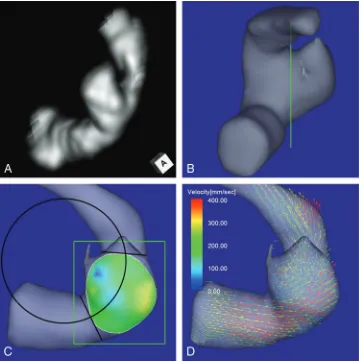
Using a function of a widely used software package (Keynote ’09, Version 5.3; Apple, Cupertino, California), we drew a circle in 2D fitting the central axis of the parent artery segment that was developing the aneurysm on an en face image of the section plane corresponding to the orifice (Fig 1C). On the image, the circle to fit the midpoints of the parent artery width at both the proximal and distal ends of the aneurysm neck was selected. The radius of the curvature was measured on the image by comparison of the radius length of the circle with the length between 2 arbitrary points of which the actual length had been measured beforehand by using a function of Flova II. The radius of the curvature in this study is defined as the radius of the circle. Drawing the circle and measuring the radius were also performed on the basis of the consensus of 3 of the authors (K.F., M.N., and F.U.).
Data Analysis
According to the positional relationship to the central axis of the parent artery, we classified the locations of the inflow zones of cerebral aneurysms into the following 3 locations: distal neck, lateral side of the neck, and proximal neck. We investigated the correlation of the radius to the inflow zone location. We also compared the inflow zone location with respect to morphologic parameters, including the maximum diameters of the aneurysm and its neck, maximum perpendicular height, maximum height, aspect ratio, and aneurysm size ratio.27-29These parameters were measured on conventional 3D TOF MRA.
Moreover, to clarify the correlation between neck size and in-flow zone location, we measured the maximum orifice ratio ob-tained by the maximum neck diameter divided by the parent ar-tery diameter and the width orifice ratio obtained by the maximum neck width divided by the parent artery diameter. The maximum neck width was measured on the direction perpendic-ular to the axis of the parent artery. Each numeric value of the various parameters was determined as the mean of the nearest 2 values independently estimated by the 3 readers.
Statistical analysis was performed by using the Mann-Whitney Utest for continuous variables.Pvalues⬍.05 were significant.
RESULTS
Of 32 sidewall aneurysms, 4D flow MR imaging revealed that the inflow zone location was the distal neck in 10 (group 1, 31.3%), the lateral side of the neck in 19 (group 2, 59.4%), and the proximal neck in 3 (group 3, 9.4%). Between groups 1 and 2 and between group 1 and the other 2 groups, there was no significant difference with respect to morphologic parameters, including the maximum and width orifice ratios (Table). Fig-ure 2 shows the distribution of the radius in the aneurysms by group. The radius was 8.3 mm (median; IQR, 4.5 mm), 4.5 mm FIG 2. The distribution of the radius of the parent artery curvature measured in 2D on an en face image of the section plane correspond-ing to the orifice in group 1, 2, and 3 aneurysms. Group 1, 2, and 3 aneurysms have inflow zone locations on the distal neck, lateral side of the neck, and proximal neck, respectively. The radius in group 1 is significantly larger than that in group 2 (asterisk1: 8.3 mm, median; interquartile range, 4.5 mm; versus 4.5 mm, median; IQR, 1.9 mm;P⬍ .0001) or those in groups 2 and 3 (asterisk2: 8.3 mm, median; IQR, 4.5 mm; versus 5.0 mm, median; IQR, 1.4 mm;P⬍.0001).
Aneurysm parameters: correlations between groups 1 and 2 and between group 1 and the other 2 groupsa
Parameters Group 1 (n= 10) Group 2 (n= 19) Group 3 (n= 3)
PValue
Group 1 vs 2 Group 1 vs Others
MD 4.6 (1.7) 5.1 (2.5) 3.7 (0.5) .491 (NS) .714 (NS)
ND 4.3 (1.2) 4.2 (1.5) 4.0 (0.7) .818 (NS) .855 (NS)
MD/ND ratio 1.1 (0.1) 1.2 (0.4) 0.9 (0.0) .383 (NS) .745 (NS)
Maximum perpendicular height 3.4 (0.7) 4.3 (2.6) 3.4 (0.3) .190 (NS) .318 (NS)
Aspect ratio 1.1 (0.1) 1.2 (0.4) 0.7 (0.2) .136 (NS) .255 (NS)
Maximum height 3.9 (0.9) 4.4 (2.5) 3.4 (0.3) .291 (NS) .555 (NS)
Size ratio 1.1 (0.1) 1.4 (0.6) 0.8 (0.3) .598 (NS) .440 (NS)
Neck width 3.4 (0.6) 3.5 (1.5) 2.3 (0.3) .335 (NS) .699 (NS)
Maximum-orifice ratio 1.1 (0.3) 1.2 (0.6) 1.2 (0.2) .568 (NS) .502 (NS)
Width-orifice ratio 0.8 (0.2) 1.0 (0.4) 0.6 (0.3) .215 (NS) .350 (NS)
Radius of curvature 8.3 (4.5) 4.5 (1.9) 5.0 (0.3) ⬍.0001 (S) ⬍.0001 (S)
Note:—S indicates significant; NS, not significant by the comparison test adjusted for thePvalue; MD, maximum diameter; ND, neck diameter. a
[image:3.594.313.530.223.516.2](median; IQR, 1.9 mm), and 5.0 mm (median; IQR, 0.3 mm) in groups 1–3, respectively. The radius in group 1 was signifi-cantly larger than that in group 2 (P ⬍ .0001) and that in groups 2 and 3 (8.3 mm [median; IQR, 4.5 mm] versus 5.0 mm [median; IQR, 1.4 mm],P⬍.0001).
All 7 aneurysms with a radius of⬎8.0 mm were group 1 an-eurysms. On the other hand, all 18 aneurysms with a radius of ⬍6.0 mm were in group 2 or 3. In 2 of 3 group 3 aneurysms, the inflow zone was located in a part of the neck extending beyond the central axis of the parent artery.
Case Presentation
Case 1. A 64-year-old woman presented with an unruptured an-eurysm at the medial C2 segment of the right ICA. Its maximum diameter and maximum neck diameter were 5.5 and 4.3 mm, respectively (Fig 1A). The inflow zone was located on the distal neck (Fig1C). The radius was 7.1 mm. A velocity vector map at peak systole revealed that high-velocity vector components came from the internal side of the curvature of the proximal parent artery and went around the central axis of the arterial part devel-oping the aneurysm (Fig 1D).
Case 2. An 80-year-old man presented with an unruptured an-eurysm at the lateral C3 segment of the right ICA. Its maximum diameter and maximum neck diameter were 5.6 and 4.1 mm, respectively (Fig 3A). The inflow zone was located on the lateral side of the neck (Fig 3C). The radius was 3.8 mm. A velocity vector map at peak systole revealed that high-velocity vector compo-nents continued along the external side of the parent artery cur-vature (Fig 3D).
Case 3. A 73-year-old man presented with an unruptured aneurysm at the medial C2 segment of the right ICA. Its maximum diameter and maximum neck diameter were 4.6 and 5.0 mm, respectively (Fig 4A). The inflow zone was located in a part of the proximal neck that extended beyond the central axis of the parent artery (Fig 4C). The radius was 4.9 mm. A velocity vector map at peak systole revealed that high-velocity vector components continued along the external side of the parent artery curvature (Fig 4D).
DISCUSSION
[image:4.594.113.476.47.409.2]the inflow zone of sidewall aneurysms is consistently on the distal neck.30,31In contrast, Szikora et al16reported that the inflow zone could be on the proximal neck in most sidewall aneurysms with a wide neck. Sforza et al32classified the locations of the inflow zones into the distal neck, side of the neck, and proximal neck by com-putational fluid dynamics analysis by using patient-specific mod-els. However, they did not clarify the incidence of aneurysms in each location of the inflow zone and the factors for determining the location.32Using 4D flow MR imaging, we recently reported that the inflow zone was not located on the distal neck in 25% of sidewall aneurysms.15In this study, we defined the locations of the inflow zones more precisely by investigating the correlation between inflow zone location and parent artery central axis on the en face image of the section plane of the aneurysm orifice by using 4D flow MR imaging. Consequently, the inflow zone was located on the distal neck in 31.3%, the lateral side of the neck in 59.4%, and the proximal neck in 9.4% of unruptured sidewall ICA aneurysms.
Computational fluid dynamics analysis by using idealized models demonstrated that the parent artery curvature more closely influenced the inflow zone location than did aneurysm
shape or size.3,4,19,33-35Imai et al19and Sato et al35revealed that the inflow zone was on the distal neck when idealized aneurysms were located inside or outside the parent artery curvature and that the inflow zone was on the outer side of the curvature when the aneurysms were located lateral to the same curvature. Their ob-servations indicated that the parent artery curvature evaluated in 2D on an en face image of the section plane corresponding to the aneurysm orifice may influence the inflow zone location.
[image:5.594.113.475.49.408.2]additional 4D flow MR imaging. These findings can help future investigators or clinicians infer the inflow zone location by using vascular curvature without having to perform flow imaging as in this study.
Szikora et al16reported the possibility that neck size influ-ences the inflow zone location and that in most sidewall aneu-rysms with a wide neck, the inflow zone could be in the prox-imal neck. In this study, we investigated the correlation between both the maximum and the width orifice ratios and the inflow zone location. However, there were no significant correlations. In addition, Sato et al35demonstrated that the inflow zone location was not dependent on the aneurysm shape by computational fluid dynamics analysis by using ide-alized models. Likewise, the morphologic parameters in this study did not influence the inflow zone location. In 2 of 3 aneurysms with an inflow zone on the proximal neck, the in-flow zone was located in a part of the neck extending beyond the central axis of the parent artery. This specific neck shape and the centrifugal effect of the blood flow in the vessel may cause the inflow zone to be on the proximal neck.
This study has some limitations. 4D flow MR imaging re-quires an imaging time of 20 –30 minutes for each patient. This relatively long time can result in motion artifacts. In addition, 4D flow MR imaging may have the limitation of spatial reso-lution.15,22These disadvantages can cause unstable and irreg-ular streamline patterns irrelevant to the vascirreg-ular shape on 4D flow MR images. High-resolution MR imaging at⬎3T may decrease these artifacts.22,36Here we investigated the correla-tion between inflow zone locacorrela-tion and the curvature of the arterial part of developing aneurysms evaluated in 2D on an en face image of the section plane corresponding to the aneurysm orifice. However, the parent artery curvature proximal to the aneurysms can also influence the location of the main flow stream in the vessel cavity and the inflow zone.22,35Further studies are needed to clarify the influence of the 3D parent artery curvature on the inflow zone location.
CONCLUSIONS
The inflow zone locations of sidewall aneurysms can be influ-enced by parent artery curvature evaluated in 2D on an en face image of the section plane corresponding to the aneurysm orifice. The inflow zone of all aneurysms with a radius of⬎8.0 mm was located on the distal neck, while that of all aneurysms with a radius of⬍6.0 mm was located on the lateral side of the neck or the proximal neck.
REFERENCES
1. Strother CM, Graves VB, Rappe A.Aneurysm hemodynamics: an experimental study.AJNR Am J Neuroradiol1992;13:1089 –95 2. Burleson AC, Strother CM, Turitto VT.Computer modeling of
intra-cranial saccular and lateral aneurysms for the study of their hemody-namics.Neurosurgery1995;37:774 – 82; discussion 782– 84
3. Liou TM, Liou SN.A review onin vitrostudies of hemodynamic characteristics in terminal and lateral aneurysm models.Proc Natl Sci Counc Repub China B1999;23:133– 48
4. Hoi Y, Meng H, Woodward SH, et al.Effects of arterial geometry on aneurysm growth: three-dimensional computational fluid dynam-ics study.J Neurosurg2004;101:676 – 81
5. Liou TM, Chang WC, Liao CC.LDV measurements in lateral
model aneurysms of various sizes.Experiments in Fluids1997; 23:317–24
6. Hassan T, Timofeev EV, Saito T, et al.A proposed parent vessel geometry-based categorization of saccular intracranial aneurysms: computational flow dynamics analysis of the risk factors for lesion rupture.J Neurosurg2005;103:662– 80
7. Cebral JR, Sheridan M,Putman CM.Hemodynamics and bleb for-mation in intracranial aneurysms. AJNR Am J Neuroradiol
2010;31:304 –10
8. Russell JH, Kelson N, Barry M, et al.Computational fluid dynamic analysis of intracranial aneurysmal bleb formation.Neurosurgery
2013;73:1061– 69
9. Gonzalez CF, Ortega HV, Moret J.Intracranial aneurysms: flow analysis of their origin and progression.AJNR Am J Neuroradiol
1992;13:181– 88
10. Graves VB, Strother CM, Partington CR, et al.Flow dynamics of lateral carotid artery aneurysms and their effects on coils and balloons: an experimental study in dogs.AJNR Am J Neuroradiol
1992;13:189 –96
11. Hayakawa M, Murayama Y, Duckwiler GR, et al.Natural history of the neck remnant of a cerebral aneurysm treated with the Guglielmi detachable coil system.J Neurosurg2000;93:561– 68
12. Tateshima S, Murayama Y, Villablanca JP, et al.In vitro measure-ment of fluid-induced wall shear stress in unruptured cerebral an-eurysms.Stroke2003;34:187–92
13. Schirmer CM, Malek AM.Critical influence of framing coil orien-tation on intra-aneurysmal and neck region hemodynamics in a sidewall aneurysm model.Neurosurgery2010;67:1692–702 14. Steiger HJ, Poll A, Liepsch D, et al.Haemodynamic stress in lateral
saccular aneurysms: an experimental study.Acta Neurochir (Wien)
1987;86:98 –105
15. Futami K, Sano H, Misaki K, et al.Identification of the inflow zone of unruptured cerebral aneurysms: comparison of 4D flow MRI and 3D TOF MRA data.AJNR Am J Neuroradiol2014;35:1363–70 16. Szikora I, Paal G, Ugron A, et al.Impact of aneurysmal geometry on
intra-aneurysmal flow: a computerized flow simulation study.
Neuroradiology2008;50:411–21
17. Steiger HJ, Liepsch DW, Poll A, et al.Hemodynamic stress in terminal sac-cular aneurysms: a laser-Doppler study.Heart Vessels1988;4:162–69 18. Castro MA, Putman CM, Cebral JR.Computational fluid dynamics
modeling of intracranial aneurysms: effects of parent artery seg-mentation on intra-aneurysmal hemodynamics.AJNR Am J Neuro-radiol2006;27:1703– 09
19. Imai Y, Sato K, Ishikawa T, et al.Inflow into saccular cerebral aneu-rysms at arterial bends.Ann Biomed Eng2008;36:1489 –95 20. Meckel S, Stalder AF, Santini F, et al.In vivo visualization and
anal-ysis of 3-D hemodynamics in cerebral aneurysms with flow-sensi-tized 4-D MR imaging at 3 T.Neuroradiology2008;50:473– 84 21. Boussel L, Rayz V, Martin A, et al.Phase-contrast magnetic
res-onance imaging measurements in intracranial aneurysms in vivo of flow patterns, velocity fields, and wall shear stress: com-parisons with computational fluid dynamics.Magn Reson Med
2009;61:409 –17
22. Isoda H, Ohkura Y, Kosugi T, et al.Comparison of hemodynamics of intracranial aneurysms between MR fluid dynamics using 3D cine phase contrast MRI and MR-based computational fluid dynamics.
Neuroradiology2010;52:913–20
23. Naito T, Miyachi S, Matsubara N, et al.Magnetic resonance fluid dynamics for intracranial aneurysms: comparison with computed fluid dynamics.Acta Neurochir (Wien) 2012;154:993–1001 24. Schnell S, Ansari SA, Vakil P, et al.Three-dimensional
hemodynam-ics in intracranial aneurysms: influence of size and morphology.J Magn Reason Imaging2014;39:120 –31
25. Lorensen WE, Cline HE.Marching cubes: a high resolution 3D sur-face construction algorithm. ACM Siggraph Computer Graphics
1987;21:163– 69
in-tensity.In:Proceedings of Society of Photo-Optical Instrumentation Engineers, Optomechatronic Machine Vision.2005;6051:605115 27. Dhar S, Tremmel M, Mocco J, et al.Morphological parameter for
intracranial aneurysm rupture risk assessment.Neurosurgery2008; 63:185–96; discussion 196 –97
28. Raghavan ML, Ma B, Harbaugh RE.Quantified aneurysm shape and rupture risk.J Neurosurg2005;102:355– 62
29. Ujiie H, Tamano Y, Sasaki K, et al.Is the aspect ratio a reliable index for predicting the rupture of a saccular aneurysm?Neurosurgery
2001;48:495–502, discussion 502– 03
30. Hoh BL, Putman CM, Budzik RF, et al.Combined surgical and endovascular techniques of flow alteration to treat fusiform and complex wide-necked intracranial aneurysms that are unsuit-able for clipping or coil embolization.J Neurosurg2001;95:24 –35 31. Byun HS, Rhee K.CFD modeling of blood flow following coil
em-bolization of aneurysms.Med Eng Phys2004;26:755– 61
32. Sforza DM, Putman CM, Cebral JR.Hemodynamics of cerebral an-eurysms.Annu Rev Fluid Mech2009;41:91–107
33. Oshima M, Torii R, Kobayashi T, et al.Finite element simulation of blood flow in the cerebral artery.Computer Methods in Applied Me-chanics and Engineering2001;191:661–71
34. Meng H, Wang Z, Kim M, et al.Saccular aneurysms on straight and curved vessels are subject to different hemodynamics: im-plications of intravascular stenting. AJNR Am J Neuroradiol
2006;27:1861– 65
35. Sato K, Imai Y, Ishikawa T, et al.The importance of parent artery geometry in intra-aneurysmal hemodynamics. Med Eng Phys
2008;30:774 – 82