1
Smart solar concentrators for building integrated photovoltaic
façades
Yupeng Wu a,*, Karen Connelly a, Yuzhe Liu a, Xiaowen Gu a, Yanfeng Gao b and George Z.
Chen c
aDepartment of Architecture and Built Environment, Faculty of Engineering, University of
Nottingham, University Park, Nottingham NG7 2RD, UK
bSchool of Materials Science and Engineering, Shanghai University, 99 Shangda Road,
Shanghai, 200444, China
cDepartment of Chemical and Environmental Engineering, Faculty of Engineering, University
of Nottingham, University Park, Nottingham NG7 2RD, UK
*Corresponding Author: Tel. +44 (0) 115 74 84011, emails: Yupeng.Wu@nottingham.ac.uk, Jackwuyp@googlemail.com
Abstract: In this study a novel static concentrating photovoltaics (PV) system, suitable for use in windows or glazing façades, has been designed. The developed smart Concentrating PV (CPV) system is lightweight, low cost and able to generate electricity. Additionally, this system automatically responds to climate by varying the balance of electricity generated from the PV with the amount of solar light and heat permitted through it into the building. It therefore offers the potential to contribute to, and control, energy consumption within buildings. A comprehensive optical analysis of the smart CPV is undertaken via 3-D ray tracing technique. To obtain optimal overall optical performance of the novel smart CPV, analysis has been based upon all necessary design parameters including the average reflectivity of the thermotropic reflective layer, the glazing cover dimension, the glazing cover materials as well as the dimensions of the solar cells. In addition, a hydroxypropyl cellulose (HPC) hydrogel polymer, suitable for use as the reflective thermotropic layer for the smart CPV system, was synthesized and experimentally studied.
Keywords: Smart Concentrating PV, Ray tracing, Optical efficiency, Thermotropic layer.
Highlights:
A smart CPV suitable for use in windows has been designed.
The optical efficiency of the smart CPV has been investigated using a 3-D ray tracing technique.
A hydroxypropyl cellulose hydrogel polymer was developed and experimentally studied for use as the potential reflective thermotropic layer for the smart CPV system.
1. Introduction
Buildings are the largest sector responsible for energy consumption and hence for CO2
2
Based on the illumination intensity focused on the solar cell, CPV can be categorised into three groups: (i) High concentration PV systems (Cg>100, where Cg is the geometrical
concentration ratio defined as the ratio of the aperture area of the concentrator and the solar cell), (ii) Medium concentration PV systems (10< Cg <100) and (iii) Low concentration PV
systems (Cg <10) [1]. High and Medium concentration PV systems are usually large in size
and require very accurate tracking, especially for the high concentrating systems that require tolerances below 0.2°. As such they are more difficult to integrate into building components and are preferred for incorporation into flat roofs. A considerable volume of research on high and medium concentration PV has been undertaken over the past few decades. Most research has attempted to improve the optical performance, seeking to obtain uniform solar radiation intensities on cell surfaces to maintain cell efficiency [2-4]. Complementary research has investigated their thermal behaviour [5].
Most of the low concentration systems such as flat reflectors and Compound Parabolic Concentrators (CPC) with a geometrical concentration ratio less than 3 can be static. This means no tracking is required and they are therefore suitable for integration into many locations on a buildings envelope. The use of conventional flat reflectors with PV modules has been widely studied since the 1970s [6, 7]. CPC has also been widely investigated, due to the fact that the theoretical maximum geometric concentration ratio can be achieved within its acceptance angles [8]. Previous research has demonstrated that the typical power output of flat reflectors and CPC PV could be 1.6 to 2 times greater than that of non-concentrating PVs [9-14].
It is becoming increasingly popular to integrate CPV/PV into building windows or glazed façades to offer aesthetically pleasing features to buildings. In addition to generating electricity, these CPV/PV can act as blinds to protect against direct sunlight and can reduce air conditioning loads (up to 65% of heat gain can be reduced) [15]. A rear diffuse reflector based flat PV concentration system has been developed and is suited to building window or glazed façade integration [16]. The solar cells are normally attached to the rear of a glass or some other transparent cover with a diffuse reflective surface provided in the spaces between the cells. In principle, the reflector diffuses the incident solar radiation through total internal reflection to the solar cells within the front cover glass. This approach can achieve close to 100% optical efficiency and generate uniform solar radiation on the solar cell surface (optical effiency is defined as the ratio of the total solar energy directly incident on the solar cell to the total incident solar energy on the concentrator aperture). This type of system also enables the capture of a large part of the diffuse solar radiation in addition to the direct radiation. Uematsu et al. [16, 17] designed two flat PV concentrators: one with mono-facial solar cells and the other with bi-facial solar cells. Optical efficiencies of 87.6% and 85.6% were reported for the two systems, respectively. The mono-facial system with a concentration ratio of 1.6 could collect 90% of the annual irradiation. The performance of the flat PV concentrator has further been investigated through improving the diffuse reflector design and replacing conventional solar cells with 2 mm wide cells [18-21]. Luminescent concentrators are also suitable for use in building windows, however, their performance needs to be further optimised, e.g. photostability over prolonged periods of UV exposure for organic dyes based concentrators still needs to be further investigated and the Quantum dots based luminescent concentrators exhibit relatively low luminescent quantum efficiency [22].
The work presented in this paper details the development and optical analysis of a novel lightweight static concentrating Photovoltaics (PV) system [27] performance suitable for use in windows or glazed façades in buildings.
2. Smart Concentrating PV (CPV) system design
3
[image:3.595.105.557.178.357.2]temperature of the thermotropic layer is below a designed threshold switching temperature, the two main components of the hydrogel, namely water and the polymer are homogeneously mixed and the layer appears transparent as shown in Figure 1(b). Above the threshold switching temperature, the components automatically separate and the thermotropic layer becomes translucent with a diffuse reflectivity, which can exceed 80%. With this relatively high diffuse reflectivity, the thermotropic layer will scatter most of the sunlight that passes through the front face of the glass for subsequent conversion to electricity as shown in Figure 1(a).
Figure 1. Cross-sectional view with working principle of the proposed concentrating PV.
This novel CPV can be thought of as an electricity-generating smart window or glazed façade as this system will respond automatically to climate, varying the balance of solar energy reflected to the PV for electricity generation and transmitted through the system into the building to provide light and heat. It therefore offers the potential to optimise energy consumption in buildings. For example, in summer, uncomfortably high solar irradiation, which in conventional design is controlled by shading devices and is therefore lost as heat to the environment, will be collected by the solar cell to generate renewable electricity. In winter, light and heat pass preferentially through the system helping to offset heating and lighting energy demands. When used in a double or triple glazed unit, the additional panes of glass installed behind the CPV would decouple the concentrator from the indoor thermal environment and therefore elimated any asscoated unwanted effects this would have.
The major challenges for the system design will be the balance between the geometrical concentration ratio and the optical efficiency of the system. For a fixed glass thickness, the effect of increasing the collector area will be to provide higher geometrical concentration ratios. Running counter to this, the effect of increased loss of light escaping from the front surface of the concentrator during total internal reflection, and transmission losses due to increased path lengths to the PV will result in reductions in optical efficiency. Small collectors will have a relatively low geometric concentration ratio, but higher optical efficiency. They would possibly however incur relative higher (per unit area) integration costs. Other variables to impact on the system efficiency include the thickness and the refractive index of the outer glazed sheet. Therefore, the optimal size of the concentrator needs to be thrououghly.
3. Optical modelling approach
Ray tracing technique has been widely used to design optical systems and to predict the optical performance of solar energy systems. A non-sequential 3D ray-tracing mode is used in the optical simulation with no pre-defined path for any ray. A ray is launched and hits an object/surface in its path and may then reflect, refract, diffract or scatter depending on the surface conditions. When the temperature of the thermotropic layer is above the designed
(b) Clear State (During winter)
G la s s s h e e t Su b s tr a te g la s s Cov e r g la s s Ai r g a p Incident solar radiation Transmitted solar radiation Reflected solar radiation CPV Solar cell
Solar cell Thermotropic layer
(a) Translucent State (During summer)
4
threshold switching temperature, it was assumed in the optical simulation that the thermotropic layer is a Lambertian type diffused reflector, the direction of reflected light from the layer is random. This although each parent ray can not be split into multiple rays which would fully represent Lambertian reflection from the thermotropic layer, this limitation can be compensated in the simulation by the application of a large amount of rays. In the simulation, radiation with known intensity is applied incident to the aperture of the smart Concentrating PV (CPV) with each ray carrying the same amount of energy. The absorbed radiation intensities in the solar cells can be calculated by the ray tracing program. After ray independent test, 100 million rays were applied on the aperture of the concentrating PV. Figure 2 illustrates a cross sectional view of the non-sequential ray tracing simulation used for the smart CPV system (temperature of thermotropic layer is above the switching temperature).
Figure 2. Non-sequential ray tracing diagram for the smart concentrating PV, 6 rays are shown for each incidence angle.
In the optical simulation, a fraction of the light escapes from the front glazing cover, when they are below the critical angle θc expressed by equation (1).
𝜃𝑐= sin−1 𝑛1
𝑛2 (1)
Where: n1 is the refractive index of the air and n2is the refractive index of the glazing cover.
The rest of the light rays satisfy the condition for Total Internal Reflection (TIR), and after multiple reflection, scattering and escape events, light manages to reach the solar cells to generate electricity.
In solar concentrator studies, an important factor for describing solar concentrator performance is the effective concentration ratio. This can be defined as the amount of radiation that will reach the solar cells at the exit aperture/absorber after concentration, or the ratio between the intensity of rays incident on the absorber to that of rays incident on a plane having the same area and same orientation located outside the concentrator. It can be expressed as the geometrical concentration multiplied by the optical efficiency as shown in equation (2).
𝐶𝑒= 𝐶𝑔× η𝑜 (2)
Where: Ce is the effective concentration ratio, Cgis the geometrical concentration ratio, and ηo
is the optical efficiency of the solar concentrating system.
4. Results and discussion PV cell
Thermotropic layer
Front glazing cover Incident light
Escaping light
Incident light
θ
5
The optical performance of this smart CPV was investigated under different conditions including variation of the average diffuse reflectivity of the thermotropic layer, the glazing cover dimensions, the type of glazing cover (with different refractive indexes) and the solar incidence angles. The criterion for choosing the optimised smart concentrating PV configuration was to obtain a balance between the highest optical efficiency and geometric concentration ratio, the effective concentration ratio was also considered.
The effects of reflectance of thermotropic layer on CPV performance
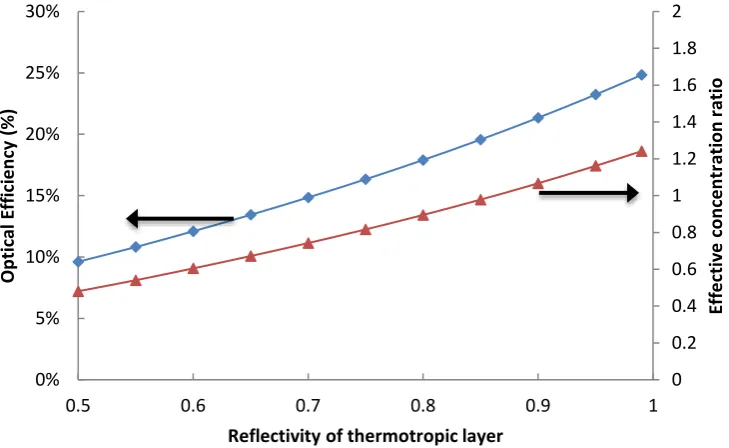
Optical simulations were undertaken for the smart concentrating PV with the average diffuse reflectivity of the thermotropic layer between 0.5 to 0.99 at a solar incidence angle of 0˚ from the vertical on the aperture cover. A common commercial glass BK7, with a refractive index of 1.52, is used for the front glazing cover with dimensions of 120 mm long by 120mm wide and 6 mm thick. Four saturn silicon BP solar cells (120mm long by 6mm wide) are integrated at the edge of the glazing cover. The absorptivity of the solar cell is 1. The geometrical concentration ratio of this smart CPV is 5x. The predicted optical efficiency and the effective concentration ratio of the smart CPV is shown in Figure 3.
[image:5.595.117.482.417.641.2]From Figure 3, it can be seen that when the thermotropic layer has an average diffuse reflectivity of 0.99, the optical efficiency of the smart concentrating PV is approximately 25%. This reduces to approximately 10%, at an average diffuse reflectivity of 0.5. Similar results can be seen for the predicted effective concentration ratio. When the average diffuse reflectivity of the thermotropic layer is 0.99, the predicted effective concentration ratio is over 1.2x. This reduces to approximately 0.5x, at an average diffuse reflectivity of 0.5. Only when the reflectivity of the thermotropic layer is over 0.9, the predicted effective concentration ratio is over 1x. The low optical efficiency is mainly due to a significant amount of light escaping from the front cover of the smart CPV. Applying equation (1), it can be found that the critical angle for this glazing is approximately 41.1°. This means that approximately 46% of the light escapes from the front aperture of the smart CPV after the first reflection.
Figure 3. Optical effiency and effective concentration ratio for the smart CPV with different average diffuse reflectivites.
The effects of refractive index of the glazing cover on CPV performance
Ideally a glass cover with higher refractive index will result in a smaller critical angle with more reflected light then trapped in the front glass cover and reaching the solar cells, therefore resulting in increased electrical power output. Ray-tracing for smart CPV with the same dimensions as the glazing cover (120 mm x 120 mm x 6 mm) and four solar cells (120 mm x 6 mm) with an average diffuse reflectivity of 0.99 at different refractive indexes have been
0 0.2 0.4 0.6 0.8 1 1.2 1.4 1.6 1.8 2
0% 5% 10% 15% 20% 25% 30%
0.5 0.6 0.7 0.8 0.9 1
Eff
e
ctiv
e
c
o
n
ce
n
tr
ation
r
atio
Op
tical
E
ff
ic
ie
n
cy
(%
)
6
investigated. The optical properties of the selected glazing cover and the corresponding critical angles are shown in Table 1. The predicted optical performance of the smart CPV with various glazing covers is shown in Figure 4.
[image:6.595.115.494.308.546.2]
Table 1. Optical properties of the glazing covers
Glazing types SCHOTT-BK7 SCHOTT-SK1 SCHOTT-LAK10 SCHOTT-SF6
Refractive index 1.52 1.61 1.72 1.81
Critical angle (°) 41.1 38.4 35.5 33.5
From Figure 4, it can be seen that the optical efficiency of the smart CPV increases from approximately 25% to 32%, when the refractive index is increased from 1.52 to 1.81. Similar results can be found for the effective geometric concentration ratio that increases from approximately 1.2x to 1.6x. This occurs due to the critical angle changing from approximately 41.1° to 33.5°, when the refractive index changes from 1.52 to 1.81.
Figure 4. Optical effiency and effective concentration ratio for the smart CPV with different types of glazing covers.
The effects of glazing cover dimension on CPV performance
Optical simulations of the novel CPV were investigated for the aperture glazing cover with thicknesses of 4 mm, 6 mm and 8 mm respectively, where the dimension (length x width) of the front glazing cover varies from 50 mm x 50 mm to 300 mm x 300 mm (the aperture area is from 0.0025 to 0.09 m2). The variation of the geometric concentration ratio with the
dimension of the glazing front cover is shown in Figure 5. As a function of geometric concentration ratio the optical efficiency and effective concentration ratio for the novel concentrating PV system are shown in Figures 6 and 7 respectively. It can be seen from Figure 6 that the optical efficiency decreases with increasing geometric concentration ratio. This results from increased optical losses due to light escaping from the top surface of the concentrator after each reflection event from the thermotropic layer as well as from transmission losses due to increased path lengths to the PV. When the geometric concentration ratio is approxmately 1.6x (dimension of the front glazing cover is 50 mm x 50 mm x 8 mm) the optical efficiency of the novel CPV is approximately 50%. It decreases to
0 0.2 0.4 0.6 0.8 1 1.2 1.4 1.6 1.8 2
0% 5% 10% 15% 20% 25% 30% 35%
1.4 1.5 1.6 1.7 1.8 1.9
Effe
cti
ve
c
o
n
ce
n
tr
ati
o
n
r
ati
o
Op
ti
ca
l e
ffic
ie
n
cy
7
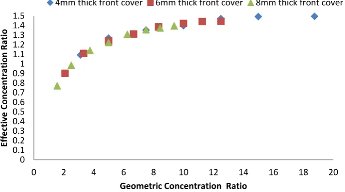
[image:7.595.142.458.141.318.2]approxmately 8% when the geomtric concentration ratio increases to 18.75x using a front glazing cover with dimensions of 300 mm x 300 mm x 4 mm. From Figure 7, when the geometric concentration ratio is above 2.5x the effective concentration ratio is over 1. Additionally there is no significant change to the effective concentration ratio, when the geometric concentration ratio is over 10x.
Figure.5 The geometric concentration ratio as a function of the glazing front cover dimension for the smart CPV.
Figure 6. The optical efficiency as a function of geometric concentration ratio for the novel CPV.
0 2 4 6 8 10 12 14 16 18 20
0 0.02 0.04 0.06 0.08 0.1
Ge
o
m
e
tr
ic
Co
n
ce
n
tr
ation
R
atio
Aperture area (m2)
4mm thick front cover
6mm thick front cover
8mm thick front cover
0% 10% 20% 30% 40% 50% 60%
0 5 10 15 20
Op
tical
E
ff
ic
ie
n
cy
Geometric concentration ratio
[image:7.595.125.485.358.568.2]8
Figure 7 The effective concentration ratio as a function of geometric concentration ratio for the novel CPV.
The effects of the solar incidental angles on CPV performance
In practise the solar zenith angle changes periodically over day and year, as well as annual daylight hours per day varying in different locations. There are also large variations in the solar energy available daily between summer and winter due to winter having shorter daytimes and lower solar altitudes as compared to those in the summer. This means that the angle of incidence of solar radiation on the absorber’s surface deviates from normal incidence. The designed solar concentrating system should therefore have a wide range of angular acceptance in order to collect most of the annual incident solar radiation and a suitable concentration ratio to reduce the system's initial cost. The effect of changing the angle of incidence of rays on a smart CPV with BK7 glazing cover (dimensions 120 mm long by 120 mm wide and 6 mm thick, Cg=5) and thermotropic layer with reflectivity of 0.99 has been
investigated. The variation of the optical efficiency as a function of the omnidirectional incidence angle is illustrated in Figure 8. Figure 9 highlights the optical efficiency of the smart CPV at various solar incident angles when angle a=0 (variation of angle b from -85˚ to 85˚). It can be observed from Figures 8 and 9 that there is no significant variation in the optical efficiency across the entire solar incidence angle. The lowest optical efficiency is approximately 25% when the solar rays are perpendicular to the aperture of the smart CPV. Optical efficiency then increases with increased angle ‘b’ due to more solar radiation reaching the solar cells directly without reflection. It can also be concluded that the smart CPV system has good angular acceptance in relation to diffuse solar radiation, in addition to direct solar radiation, which is particularly advantageous for the northern European climate.
0 0.1 0.2 0.3 0.4 0.5 0.6 0.7 0.8 0.91 1.1 1.2 1.3 1.4 1.5
0 2 4 6 8 10 12 14 16 18 20
Eff
e
ctiv
e
Co
n
ce
n
tr
ation
R
atio
Geometric Concentration Ratio
9
[image:9.595.146.447.74.236.2]Figure 8. Optical efficiency of the smart CPV at omnidirectional solar incident angle.
Figure 9. Optical efficiency of the smart CPV, when angle a=0.
Power output of the smart CPV
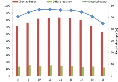
Power output of a smart CPV has been investigated on a sunny day, 30th June 2014 in London (latitude, longitude of 51˚32’28’’N, 0˚7’41’’W, respectively) with realistic values of direct and
diffuse solar radiation. The smart CPV has an aperture area of 1.44 m2 with 100 modules each
with dimensions of 120 mm x 120 mm x 6 mm. The opitcal simulation has been undertaken for a south facing system. The reflectivity of the thermotropic layer is 99% and the aperture cover is made of BK7. Figure 10 shows a profile of hourly values for both direct and diffuse solar radiation (from 8:00 to 16:00) and the electrical output generated from the smart CPV. A maxmium electricital ouput of approximately 57W can be achieved at 11:00 on that day.
20% 21% 22% 23% 24% 25% 26% 27% 28% 29% 30%
-90 -80 -70 -60 -50 -40 -30 -20 -10 0 10 20 30 40 50 60 70 80 90
Op
tical
e
ff
ic
ie
n
cy
Incident Angle b (˚)
smart CPV
10
Figure 10. Simulation results of electrical output of smart CPV under a sunny day.
5. Development of the thermotropic layer
A hydroxypropyl cellulose (HPC) hydrogel polymer was chosen as the thermotropic material for preliminary testing for the ‘smart concentrating PV’ application. Thermotropic hydrogels fulfil the phase separation characteristics required including high transmittance below the switching temperature, low transmittance and high diffuse reflectivity above the switching temperature, low hysteresis, flexible switching temperature range and steep switching gradients. Since the backbone of the HPC structure is cellulose, a natural organic polymer source, its use in this system resolves issues around both toxicity and cost.
The thermotropic HPC hydrogel is composed of mostly water as well as HPC, a water soluble polymer with hydrophobic groups. Inorganic salts such as NaCl can be added to the hydrogel composition in order to adjust the switching temperature. Figure 11 demonstrates the differing structure of the hydrogel both below and above the switching temperature.
0 10 20 30 40 50 60
0 100 200 300 400 500 600 700 800 900 1000
8 9 10 11 12 13 14 15 16
El
e
ctr
ic
al
o
u
to
p
u
t
(W)
solar
r
ad
iation
(
W/m
2)
Time
11
Figure 11. Conceptual illustration of the phase transition from the low temperature, isotropic state below the switching temperature to the anisotropic, high temperature phase above the
switching temperature [23].
Below the switching temperature the hydrophilic groups of HPC are fully hydrated and effectively expand, uncoil and separate due to a sheath of tightly bound water molecules surrounding them. HPC is therefore fully dissolved in the water with strong hydrogen bonding between the polymer and water molecules resulting in a homogeneous, isotropic solution. At the switching temperature HPC becomes dehydrated due to additional thermal energy disrupting the polymer-water hydrogen bonds. Consequently phase separation occurs with water quenched out of the polymer network. With sufficient disparity between the refractive indices of these two phases light is scattered, rather than transmitted, with a resultant ‘clouding’ of the system. [24, 25] The presence of an electrolyte such as NaCl in aqueous HPC weakens hydrogen bonding between the polymer and water molecules accompanied by increased salt-water interactions. This enhances the hydrophobic behaviour of the polymer as can be seen in Figure 11 and therefore lowers the switching temperature. [26]
The synthesis procedure for HPC is outlined as follows. Firstly the required mass of HPC was magnetically stirred into half the quantity of water required, which was pre-heated to between 50 to 60°C, for several minutes until all HPC had dissolved. The rest of the water was then added to the HPC solution and magnetically stirred for several hours at room temperature.
12
Figure 12. UV-Vis spectra for 2.0 wt. % HPC in aqueous solution showing high transmission below 39°C and low transmission after 45°C.
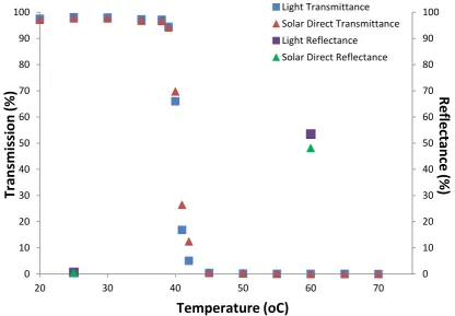
Reflectance measurements were also measured from the 2 wt. % HPC sample using an Ocean Optics USB2000+ Spectrometer with ISP-REF Integrating Sphere. Reflectivity of the sample was measured both below and above the switching temperature. Figure 13 shows both the transmittance and reflectance data for the 2 wt. % HPC sample. The average transmission was calculated for light transmittance (wavelength range 380 - 780 nm) and direct solar transmittance (wavelength range 300 – 1100 nm) and average light reflectance (wavelength range 400 – 780 nm) and direct solar transmittance (wavelength range 400 - 1000 nm) using the methods outlined in BSI Standards BS EN 410:2011. At 50% transmittance a switching temperature of around 40°C is observed which has a steep switching gradient. Figure 13 also shows that below the switching temperature the reflectance of the 2wt. % HPC sample is nearly 0%, and upon heating the sample above the switching temperature an average 50% reflectance is obtained. Both transmittance and reflectance measurements for the 2 wt. % HPC sample are encouraging for further development of the HPC system as a suitable thermotropic material for the proposed ‘smart CPV’ system.
0 10 20 30 40 50 60 70 80 90 100
35 oC
39 oC
40 oC
41 oC
42 oC
45 oC
70 oC
Tr
an
smi
tt
an
ce
(%)
13
Figure 13. UV-Vis averaged transmittance and reflectance data for 2.0 wt. % HPC in aqueous solution with increasing temperature.
6. Conclusion
A smart CPV system, suitable for use in windows or glazing façades, was designed and comprehensively studied optically using a 3-D ray tracing technique. It was found that the optical efficiency of the smart CPV decreases with the increase of the geometrical concentration ratio. However there is no significant change to the effective concentration ratio when the geometric concentration ratio is over 10x. The low optical efficiency of the smart CPV is mainly due to a significant amount of light escaping from the front cover. The smart CPV shows good angular acceptance for a wide range of solar incidence angles. In addition, a hydroxypropyl cellulose (HPC) hydrogel polymer was developed for preliminary testing to be used as the reflective thermotropic layer of the proposed smart CPV. Both transmittance and reflectance measurements for a representative 2 wt. % HPC sample are encouraging for further development of the HPC system as a suitable thermotropic material for the proposed ‘smart CPV’ system. Overall the results support the potential for building energy saving and electricity generation by using the proposed ‘smart CPV’ system. It also indicates a novel way of developing the next generation of smart windows and concentrating PV systems.
Acknowlegment
This work was supported by Faculty of Engineering, University of Nottingham UK through Dean of Engineering Prize and Engineering Research Placements scheme.
References
[1] Chemisana, D., (2011) Building Integrated Concentrating Photovoltaics: A review, Renewable and Sustainable Energy Reviews, 15, 603-611.
[2] Nabelek, B., Maly, M. and Jirka, Vl. (1991) Linear fresnel lenses, their design and use. Renewable Energy, 1, 403-408.
0 10 20 30 40 50 60 70 80 90 100
0 10 20 30 40 50 60 70 80 90 100
20 30 40 50 60 70
Light Transmittance Solar Direct Transmittance Light Reflectance
Solar Direct Reflectance
Temperature (oC)
Tr
an
smi
ss
ion
(%)
Refl
ect
an
ce
14
[3] Andreev, V. M., Grilikhes, V. A., Khvostikov, V. P., Khvostikova, O.A., Rumyantsev, V. D., Sadchikov, N. A. and Shvarts, M. Z. (2004) Concentrator PV modules and solar cells for TPV systems. Solar Energy Materials & Solar cells, 84, 3-17.
[4] Ryu, K., Rhee, J. G., Park, K. M. and Kim, J. (2006) Concept and design of modular Fresnel Lenses for Concentration solar PV system. Solar Energy, 80, 1580-1587.
[5] Wu, Y., Eames, P., Mallick, T. and Sabry, M. (2012) Experimental characterisation of a Fresnel lens photovoltaic concentrating system, Solar Energy, 80, 430-440.
[6] Hollands K.G.T. (1971) A concentrator for thin film solar cells, Solar Energy, 17, 291-295 [7] Fraidenraich N. (1992) Analytic solutions for the optical-properties of V trough concentrators, Applied Optics, 31: 131-139.
[8] Mallick, T.K., Eames, P.C., Hyde, T.J. and Norton B. (2004) The design and experimental characterisation of an asymmetric compound parabolic photovoltaic concentrator for building façade integration in the UK, Solar Energy, 77, 319-327.
[9] Freilich J., and Gordon J.M. (1991) Case-study of a central-station grid interitie photovoltaic system with V-trough concentration, Solar Energy, 46, 267-273.
[10] Rönnelid M., Karlsson B., Krohn P. and Wennerberg J. (2000) Booster reflectors for PV modules in Sweden, Progress in Photovoltaics: Research and Applications, 8, 279-291. [11] Tripanagnostopoulos Y, Nousia TH. Souliotis M, Yianoulis P. Hybrid photovoltaic/thermal solar Systems. (2002) Solar Energy, 72, 217-234.
[12] Zacharopoulos, A., Eames, P. C., McLarnon D. and Norton B. (2000) Linear Dielectric Non-Imaging Concentrating Covers For PV Integrated Building Facades, Solar Energy, 68, 439-452.
[13] Mallick TK, Eames PC. (2007) Design and fabrication of low concentrating second generation PRIDE concentrator, Solar Energy Materials and Solar Cells, 91, pages 597-608. [14] Wu, Y. (2015) Optical and thermal analysis of Building Integrated Asymmetric Compound Parabolic Concentrating Photovoltaics systems Renewable Energy (under review).
[15] Davidsson, H., Perers, B. and Karlsson B. (2010) Performance of a multifunctional PV/T hybrid solar window, Solar Energy, 84, 365-372.
[16] Uematsu T., Yazawa Y., Tsutsui K., Miyamura Y., Ohtsuka H., Warabisako T., and Joge T., (2001a) Design and Characterisation of Flat-Plate Static- Concentrator Photovoltaic Modules, Solar Energy Materials & Solar Cells, 67, 441-448.
[17] Uematsu T., Yazawa Y., Joge T., and Kokunai S., (2001b) Fabrication and Characterisation of a Flat-Plate Static Concentrator Photovoltaic Module, Solar Energy Materials & Solar Cells, 67, 425-434.
[18] Uematsu T., Yazawa Y., Miyamura Y., Muramatsu S., Ohtsuka H., Tsutsui K., and Warabisako T. (2001c) Static Concentrator Photovoltaic Module with Prism Array, Solar Energy Materials & Solar Cells, 67, 415-423.
[19] Matsushima T., Setaka T., and Muroyama S. (2003) Concentrating solar module with horizontal reflectors, Solar Energy Materials & Solar Cells, 75, 603-612.
[20] Yoshioka K. Joizumi. K and Saitoh T. (2003) Simulation and fabrication of flat-plate concentrator modules, Solar Energy Materials & Solar Cells 75, 373-380.
[21] Weber K. J., Everett, V. Deenapanray P.N.K, Franklin, E. and Blakers A. W. (2006) Modeling of static concentrator modules incorporating lambertian or v-groove rear reflectors, Solar Energy Materials & Solar Cells, 90, 1741-1749.
[22] Klampaftis, E., Ross, D., McIntosh, K.R. and Richards B.S. (2009) Enhancing the performance of solar cells via luminescent down-shifting of the incident spectrum: A review, Solar Energy Materials & Solar Cells, 93, 1182-1194.
[23] Watanabe, H. (1998) Intelligent window using a hydrogel layer for energy efficiency, Solar Energy Materials & Solar Cells, 98, 203-211.
[24] Resch, K. and Wallner, G. M. (2009) Thermotropic layers for flat-plate collectors – A review of various concepts for overheating protection with polymeric materials, Solar Energy Materials & Solar Cells, 93, 119-128.
15
[26] Xia, X., Tang, S., Lu, X., and Hu, Z. (2003) Formation and volume phase transition of hydroxypropyl cellulose microgels in salt solution, Macromolecules, 36, 3695-3698.