A Study of Processing Parameters on the Carburization of C2R Steels
P.O. Atanda1*, O.E.Olorunniwo1, L.E. Umoru1, and A.D. Adeyeye2
1
Department of Materials Science and Engineering Obafemi Awolowo University, Ile-Ife. Nigeria.
2
Department of Industrial Engineering, University of Ibadan. Nigeria
*Correspondence Author email: [email protected] Phone: +2348033603709
ABSTRACT
This study reports an investigation of the effect of carburizing variables – temperature, time and percentage of energizer –on the case properties of C2R steel obtained from HMT Ltd. India. A carburizer consisting of hardwood charcoal and coke respectively in the ratio of 2:1 was used for the research with sodium carbonate as the energizer. The carburizing box was filled with 20 mm thick carburizer compound prior to fixing the steel samples in place. The specimens were carburized using different percentages of energizers (10, 20 and 30%) at different temperatures
(820, 860, 900 and 940oC) for different times (from one to five hours). All the specimens were
quenched from carburizing temperature, ground to polished surfaces and then etched for ten minutes in 25% Nital. The case depth was measured using the calibrated ocular of an inverted metallurgical microscope fixed at 100 x magnification. The hardness values of the C2R steel cases were measured with a micro hardness tester that uses diamond pyramid indenter. The results of the study showed that the average hardness of the C2R steel cases increased with temperature for any given carburizing time and temperature. For a given percentage energizer and temperature, the case depths and hardness increased with time. Increase in the percentage energizer however decreased the activation energy required for diffusion to occur exponentially.
Keywords : Carburizer, Energizer, Heat treatment, Case depth, Activation Energy, Diffusion.
1. INTRODUCTION
The service conditions of many steel components such as gears, cams, valves etc, make it necessary for them to possess both hard and wear resistant surfaces but tough and shock resistant
cores [1]. A low carbon steel of approximately 0.1% carbon will be tough while a high carbon steel of about 0.9% or more will possess adequate hardness (and inherently low toughness) when suitably heat-treated. The combination of hard, wear resistant surface and tough core required in the aforementioned components involves the treatment of a shock- resistant steel so as to alter the nature of the surface in order to increase the hardness while the core remains more or less unaltered.
There are two major processes through which such an alteration of the surface layers of steel components may be carried out, namely, (i) processes which impart surface hardness by changing the microstructure of the surface skin without changing the chemical composition of the surface. Such steel must not have a carbon content of less than 0.4% for them to be amenable to hardening (by any of flame, induction, laser, and electron beam hardening) (ii) processes which impact surface hardness by changing the surface chemistry of the steel by diffusing carbon, nitrogen or both carbon and nitrogen into its surface. Steels for this process may have a carbon content of about 0.1%. Examples of this latter process include carburizing, nitriding, cyaniding, diffusion coating, and hard surfacing.
The method of carburizing was selected for this investigation because it has the advantages of ease of operation, adaptability and portability of the equipment required, ability to heat-treat component after surface- finishing (since there is little oxidation, decarburization or distortion), and the ease of producing deeper zones of case depth.
It is known that the inward diffusion of the carbon takes place at a rate which depends on the chemical composition of the steel, the carburizing temperature and the chemical composition of the carburizing mixture [2, 3]. Established is a concentration gradient in respect of carbon from the skin to the core of the steel. With increase in the carburizing activity of the carburizing compound, the concentration is made steeper; the depth of penetration is not however increased to the same extent.
Although the stress is within the fatigue limit, the stress in the case is due both to the increased strength of the surface layer and to the development of favourable compressive residual stresses close to the surface.
For a successful carburization, a control of all these parameters; the carburizing temperature, carburizing time, and chemical composition of the carburizing compound must be effected [5,6,9].
In this work, the effect of carburizing variables on C2R steel used in machine tool operation for the manufacture of different machine tool components has been studied with the aim of improving both the production processes and the manufactured components used in machine tools operation [7, 8]. The components studied include gears of different shapes and contours, like the spiral, bevel, worm, taper, helical, etc.
2. MATERIALS AND METHODS
The composition of the C2R steel used in this work is given in the Table 1 below. The carburizer was made in the ratio 2:1, hardwood charcoal and coke, with sodium carbonate
(Na2CO3) as energizer. The composition of carburizer used was shown in Table 2 below. The
steel, C2R, is normally used for the manufacture of different kind of gears, shafts, worm-wheel, rack and pinion etc, in machine tool building. A 22.0mm diameter cylindrical specimen was used in order to avoid “edge” effect during carburizing. Clay was used to lute the lid of the carburizing container.
Table 1. Chemical composition of C2R steel (Diameter of specimen=22mm, Hardness= 240(HB)
C(%) Si(%) Mn(%) P(%) S(%) Cu(%) Cr(%) Ni(%) Sn(%)
0.15 0.23 0.50 0.040 0.040 0.025 0.10 0.011 0.05
The box was first filled with the carburizer compound about 20mm thick which was then rammed and the components were placed about 25mm away from the sides of the carburizing box. A digital chemical balance was used to weigh the generator (63% charcoal and 37% of
coke) and the energizer (Na2CO3) in the ratios 9:1, 8:2, and 7:3. A cylindrical steel container
(diameter 60mm) was used to contain the carburizer and the specimen. Carburizing was done in a heat-treatment furnace (electrically energized).
The generator (63% charcoal and 37% coke) and energizer (Na2CO3) were weighed respectively
according to the formulation in Table 2. The specimens were packed with the carburizer in the carburizing container making sure that the specimen was covered with about 20mm of carburizer. The lid was coated with clay and placed in the furnace.
The specimens were carburized at different temperatures (820, 860, 900 and 940oC), for different
lengths of time (from one to five hours) and different percentages of energizers (10,20 and 30). All the specimens were quenched from the carburizing temperature, sectioned, ground and
polished. The specimens were etched with 25% Nital (25% HNO3 and 75% ethyl alcohol) for
about ten minutes. Case depth was measured with micrometer screw gauge and hand lens. The hardness of the case was measured with microhardness tester using diamond pyramid indenter.
Table 2. Composition of carburizer.
Generator (wt%) Energizer (wt%)
90 80 70
10 20 30
3. RESULTS AND DISCUSSION
In order to analyze the results of this investigation, particularly as regards the effect of the carburizing variables on the depth and hardness of C2R steel cases, graphs of Figs.1 to 13 have been used to summarize pictorially the effects of the investigated variables. Also, plates 1a, 1b, 2a and 2b are included to reveal the effects of carburizing time, temperature and proportion of carburizing energizer, Na2CO3 on case depth microstructures.
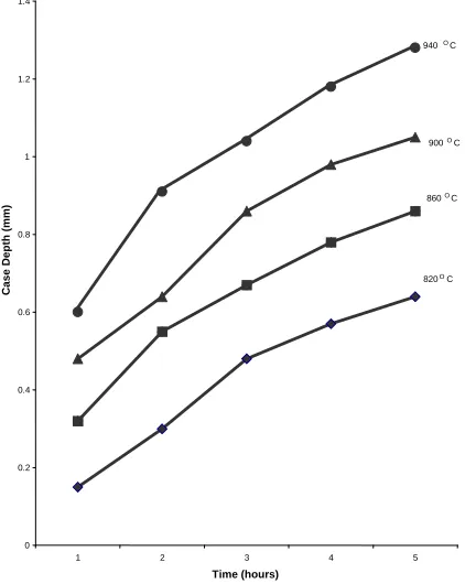
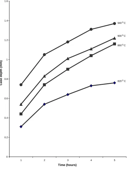
It is clear from Figs. 1-3 that the case depth increases with increase in carburizing time and
temperature. Significantly, the three figures show that 820oC should not be considered as a
carburizing temperature for C2R steel because of its case depth that was relatively low even up
to higher carburizing times. Temperatures 860oC and 900oC for carburizing exhibited similar
features in terms of their slopes, an indication that they have comparable activation energies [3,
10]. For all the three energizer compositions investigated, the graphs show that 940oC stands out
as an effective carburizing temperature.
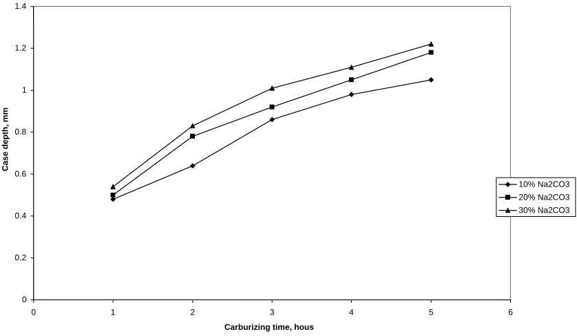
Figures 4, 5 and 6 show that carburizing time almost exhibited linear relationship with case depth. Generally, the depth of the cases also increased with carburizing time and temperature.
the carbon potential of the carburizer and consequently a higher diffusion rate of carbon into steel leading to an increased case depth as the percentage of the energizer (Na2CO3) increases.
O
C 940
O C
900
860 O
C
C 820 O
2 3 4 5
1 1.4
1.2
1
0.8
0.6
0.4
0.2
0
Case Dep
th
(
mm)
[image:5.612.77.288.128.393.2]Time (hours)
Fig. 1. The Relationship between Case depth (mm) and temperature for different carburizing time using 10% Na2CO3 (as quenched).
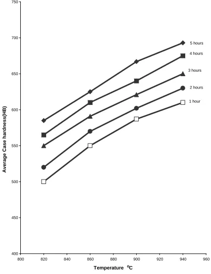
It can also be found in the figures earlier referred to that for any given carburizing temperature and time the hardness of the case increases with the percentage of energizer used in the carburizer. This is so because higher proportion of energizer implies an increase in carbon potential and hence more carbon would have diffused into the steel than when lower percentage of energizer was used.
An increase in carbon content in the case lead to an increase in its hardenability on quenching and since there is more carbon in the case with high percentage of energizer, the case would be harder.
1.4
960 O C
900O
C
860 O C
C 820 O
2 3
Time(hours)
4 5
1 1.2
1
Case d
e
p
th
(
mm)
0.8
0.6
0.4
0.2
[image:6.612.79.291.75.362.2]0
Fig 2 The relationship between case depth(mm) and temperature for different carburizing time using 20% Na2CO3 ( s quenched)a
1.6
940 O C
900 O C
860 O
C
C 820 O
1 2 3 4
1.4
1.2
1
Case d
e
p
th
(
mm)
0.8
0.6
0.4
0.2
0
5
Time (hours)
Fig 3The relationship between case depth(mm) nd temperature for different carburizing time using 30% Na
a
[image:6.612.79.286.403.677.2]C 940 O
C 900 O
C 860 O
C 820 O
4
1 2 3
Time ( hours)
750 700 650 600 550 500 450 400 Aver ag e cas
e h
a rd n ess ( HB) 5
Fig 4 The relationship between average case hardness(HB) and carburizing time at various temperatures using 10% Na2CO3
(as quenched)
.
850
940 O C
900 O C
860 O C
820 O C
2 1 800 750 700 C ase ha rdnes s ( H B ) 650 600 550 500 450 400
3 4 5
Time (hours)
900
940 O
900 O
C 860 O
O C
820
2 1
C
850
C
800
Case Hard
n
e
ss
(HB) 750
700
650
600
550
500
3 4 5
Time (hours)
Fig 6 The relationship between case hardness(HB) and carburizing time at various temperature using 30% Na2CO3.( as quenched)
1.2 1.4
30% Na2CO3 20% Na2CO3 10% Na2CO3 1
Case depth,
mm
0.8
0.6
0.4
0.2
0
0 1 2 3 4 5 6
[image:8.612.80.286.118.352.2]Carburizing time, hous
Fig. 7 The relationship between case depth and proportion of energizer(Na2CO3) at carburizing
[image:8.612.83.502.411.655.2]Fig 8 The relationship between case depth and proportion of energizer(Na2CO3) at carburizing
temperature of 940oC
0
Carburizing time, hours
3
0 1 2
1.6
1.4
1.2
Case depth,
mm 1
0.8
10% Na2CO3 20% Na2CO3 30% Na2CO3 0.6
0.4
0.2
4 5 6
5 hours 4 hours
3 hours
2 hours
1 hour
920 9
C
o
00 880 860 840 820 750
700
650
600
550
500
450
400 800
Aver
ag
e C
ase h
a
rd
n
e
ss(
HB)
940 960
Temperature
[image:9.612.76.289.395.672.2]5 hours 4 hours 3 hours 2 hours 1 hour 920 860
Temperature oC
900 880 840 820 800 850 800 750 550 600 650 700 A v erage ca se h a rdne ss( H B ) 500 450 400 940 960
Fig.10 The relationship between average case hardness and temperature for various carburizing time for 20% Na2CO3 (as quenched)
3
5 hours
4 hours
3 hours
2 hours
1 hour
860 840 820 900 850 800 750 700 650 600 550 500 450 400 800 Aver ag e C ase h a rd n e ss( HB) 880 90 o 0 C
920 940 960
Temperature
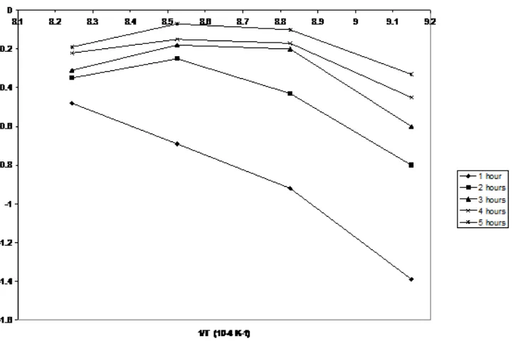
Fig 12 : The variation of linK with I/T for various carburizing time using 10% Na2CO3
[image:11.612.83.447.414.654.2](Energizer) as quenched.
Fig 13. The variation of linK with I/T for various carburizing time using 20% Na2CO3
Plate 1(a) Macrostructure of a specimen, carburized at 9400C for 3 hours The carburizer contained 20% Na2CO3 Etched in 25% Nital.
Magnification : x 2
Plate 1(b) Macrostructure of a specimen, carburized at 9400C for 4 hours The carburizer contained 20% Na2CO3 Etched in 25% Nital. x2
Magnification : x2
Plates 1(a)and 1(b) show the effect of carburizing time on the case depth .The ring shape layer in the case The inner ring is the transition zone where the carbon content of the case decreases gradually into the carbon content of the case .
Plate 2 (a) Macrostructure of a specimen, carburized at 9000C for 3 hours The carburizer contained 20% Na2CO3 Etched in 25% Nital.
Magnification: x2
Plate 2 (b) Macrostructure of a specimen, carburized at 9000C for 3 hours The carburizer contained 20% Na2CO3 Etched in 25% Nital. x2
Magnification : x2
The effect of the carburizing variables on the activation energy of the process is contained in Figs. 12 and 13. The two figures show that for any given carburizing time, the activation energy decreases as percentage energizer increases. The shape of the curves suggests that the rate of change of activation energy with percentage energizer is instantaneous. Since increase in
energizer concentration increases the carbon potential (i.e. increases the CO to CO2 ratio) [2, 6],
it implies that the number of carbon atoms at the surface of the steel will also be increased leading to a decrease in the activation energy. In addition the number of atoms that possess enough energy to diffuse also increases. Also obvious from these figures is the fact that activation energy decreases as time increases. The relation is an exponential one and the rate of change of activation energy with time is instantaneous. Decrease in activation energy is higher at shorter period than longer period.
The decrease in activation energy with increase in time may be due to increase in carbon concentration in the surface layer. However, decrease in the rate of a change of activation energy with time may be as a result of the decreasing carbon potential of the carburizer with time.
4. CONCLUSIONS
The depth of resulting case and the hardness obtained depends on the factors summarized below
(a) The case depth obtained increase with temperature, time and percentage energizer.
(b) The case hardness increases with the percentage energizer and carburizing time for
a given temperature.
(c) For a given temperature and percentage energizer, case depth and hardness increases with time.
(d) For a given percentage energizer and time increase, in temperature increase the case depth and hardness.
(e) For a given time and temperature, increase in percentage energizer increases the case depth and its hardness.
(f) Increase in the percentage of energizer decreases the activation energy for diffusion to occur exponentially.
(g) Increase in time decreases the activation energy for diffusion to occur exponentially.
REFERENCES
[1] America Society of Metals(1964); Metals Hand book, Heat-treating, cleaning and finishing. 8th ed.
[2] M.A. Majid ad H.C. Child; Effect of carburizing on unidirectional bending fatigue strength of low alloy steel. (1983). Journal of Metals Technology, Vol. 10 page 173.
Moscow.
[4] Smith, W.F(1970); Principles of Materials Science and Engineering. 2nd ed. Mc GrawHill Int.
ed.
[5] Simon, E.N(1974); Dictionary of Metal Heat Treatment. Frederic Muller Ltd, London.
[6] Prabhudev K.H (1997) Handbook of Heat treatment of Steels. 4th ed. Tata Mc GrawHill
Publishing Company Ltd. New Delhi.
[7] Rajput R.K(2002) Materials Science and Engineering. 2nd ed. S.K.Katara & Sons, New Delhi.
[8] Degarmo E. Paul, Black J.T & Kohser A. Ronald(1997) Materials and Processes in
Manufacturing. 8th ed. Prentice-Hall of India Private Ltd., New Delhi.
[9] George S.Brady and Henry R. Clauser(1989) Materials Handbook.12th ed. Mc Graw-Hill
Publishing Company, New York.
[10] Higgins R.A (1983) Engineering Metallurgy Part 1.