Analysis of Reflectivity and Shielding Effectiveness
of Absorbing Material–Conductor Laminate for
Electromagnetic Compatibility
Cheruku D. Raj1, Gottapu S. Rao2, Pappu V. Y. Jayasree1, Budumuru Srinu1, Pappula Lakshman1
1Department of ECE, GITAM Institute of Technology, GITAM University, Visakhapatnam, India; 2Department College of
Engi-neering, Andhra University, Visakhapatnam, India. Email: [email protected]
ReceivedFebruary 2nd, 2010; revised March 29th, 2010; accepted April 3rd, 2010.
ABSTRACT
An absorbing material–conductor laminateis widely used for electromagnetic compatibility of electronic circuits at microwave frequencies. Such a laminate when properly designed will exhibit good results in terms of electromagnetic interference and compatibility. In this paper, microwave absorbing materials like 1) Ca-NiTi hexa ferrite composites
(Ca (NiTi)x Fe12-2xO19) for x = 0.4, 2) M-Type Barium ferrites (BaFe12-2xAxCoxO19 for the tetravalent A ions, Ru4+ is
chosen), 3) MnZn ferrite-Rubber composites with volume fraction vf = 0.4, 4) Carbonyl-Iron particle composites with
volume fraction vf = 40% and conducting materials like copper, stainless steel are considered to form the interface in
the laminate. Mathematical formulations are carried out for the estimation of reflectivity and shielding effectiveness of absorbing material–conductor laminateat microwave frequencies Analysis is also carried out for various thicknesses of the microwave absorbing material and conducting material in the laminate. The reflectivity and shielding effectiveness depends not only on the type of the selected material in the laminate, but also their thickness in the laminate and fre-quency of operation.
Keywords: Electromagnetic Compatibility, Reflectivity, Shielding Effectiveness, Propagation Constant, Attenuation Constant, Reflection Coefficient, Transmission Coefficient, Laminate, Interface
1. Introduction
Electromagnetic compatibility of an electronic circuit at microwave frequencies is of prime concern in the design of microwave circuits. External electromagnetic radia-tions should not interfere with the basic circuit perform-ance and as well the circuit should not radiate electro-magnetic energy to interfere with other neighboring cir-cuits. The best method of achieving such an electromag-netic compatibility is to house the circuit in an enclosure made with a laminate which attenuates the radiations from the circuit and stops the external radiations inter-fering with the circuit. A laminate of microwave absorb-ing material-metallic conductor is considered to improve the electromagnetic compatibility capability of the circuit. This laminate is designed such that the radiation from the microwave circuit is attenuated to a very large extent before it propagates out of the circuit housing and simul-taneously, also shields the microwave circuit from exter-nal radiation inferences. A well designed conducting metal with appropriate thickness provides the required
shielding ability and a suitably selected microwave ab-sorbing material with high attenuation constant arrests the radiations from the circuit. The thickness of the ma-terial layers in the laminate are so designed such that the reflectivity and shielding effectiveness of the laminate are achieved as per the requirement of the circuit com-patibility considerations.
2. Reflectivity
Reflectivity of the lamination can be estimated using the transmission line analysis for normal incidence. Reflec-tion coefficient [1] at an interface of absorbing material- conducting metal can be given as
1 c A
c A
(1) where c is the intrinsic impedance of metallic con-ductor and A is the intrinsic impedance of the micro-wave absorbing material.
The intrinsic impedance [2] of metallic conductor can be estimated as
1
cc
f
j
(2)
Where permeability of themetal, c o rc (3) conductivity of the metal, o r (4)
rc
is relative permeability of the absorbing material,
r
is the relative conductivity of the conductor with respect to copper, o is free space permeability, o is conductivity of copper and f is the frequency of opera-tion.
The intrinsic impedance of absorbing material can be derived to be
22 2 A A A f
(5)
Where A is the permeability of absorbing material = o rA, rA is relative permeability of absorbing ma-terial and A is the propagation constant of the absorb-ing material [3] which can be given as
2
2
A rA rA
rA rA rA rA
f j
c f
j j j
c (6)
Relative permeability,rA rA jrA (7) Relative permeability, rA rA j rA (8)
c is the speed of light in free space.
The reflection coefficient at the interface of free space- absorbing material is very small and is neglected in this
analysis.
The reflectivity at the interface of absorbing material- conducting metal in the laminate, as shown in the Figure 1, is the path loss of the electromagnetic energy while it propagates from free space to absorbing material–metal interface and back after reflection by the metal in the int- erface.
Thus, the reflectivity of the laminate can be derived as
1 2
1
A A A A
A A
t t
t
r e e
e
(9)
Where tA is the thickness of the absorbing material and A is the attenuation constant of the absorbing ma-terial [3] can be given as
Reflectivity expressed in dB is
10 20
R log r dB (11)
3. Shielding Effectiveness
Shielding effectiveness of the laminate of microwave ab- sorbing material and conducting metal is the total atte- nuation loss of the electromagnetic energy while it pro- pagates through the interface. In other words, the shield-ing effectiveness is nothshield-ing but transmission coefficient of the interface of microwave absorbing material and conducting metal in the laminate.
The transmission coefficient of the interface at two boundaries (absorber-conductor & conductor-free space) [2] is given as
o A
8 oA Ac
c c o
p
(12)
Where ois the free space intrinsic impedance = 120 ohms.
Reflection coefficient [2] at absorbing material-metal interface, q1 and that at conductor-free space interface
2
q can be given as
1
A o A
A o A
z c q z c
(13)
2
c A c o
c A c o
q
(14) where z c
, impedance to the right of the absorber-metal interface and can be derived as
2
22
A rA rA rA rA rA rA rA rA rA rA rA rA
f c
[image:3.595.56.279.313.470.2]
Figure 1. Reflectivity of microwave absorber–conductor la- minate
Figure 2. Shielding effectiveness of microwave absorber– conductor laminate
cz c
o c c c c c
c c c o c c
cosh t sinh t
cosh t sinh t
(15)
c
t is thickness of the metallic conductor and c is the propagation constant in the metallic conductor [2] given as
1
c j f
(16) The total transmission coefficient [2] across the lami-nate of the two interfaces can thus be derived to be
12 2
1 2
1 A At 1 c ct A At c ct T p q e q e e
(17)
The Shielding effectiveness of the microwave absorb-ing material-metal laminate can thus be given in decibels as
10 20
S log T dB (18)
4. Results and Conclusions
Analysis is carried out for the estimation of reflectivity (equation 11) of the laminate of microwave absorbing material-metallic conductor for various types of absorb-ing materials, conductabsorb-ing materials and thickness of ma-terial layers in the laminate. Popular and widely used microwave absorbing materials like 1) Ca-NiTi hexa ferrite composites (Ca(NiTi)xFe12-2xO19) for x = 0.4 [4], 2)
M-Type Barium ferrites (BaFe12-2xAxCoxO19 for the
tet-ravalent A ions, Ru4+ is chosen) [5], 3) MnZn ferrite-
Rubber composites with volume fraction vf = 0.4 [6] and
4) Carbonyl-Iron particle composites with volume fraction vf = 40% [3,7] along with copper as conductor is
consid-ered for the estimation of optimum reflectivity.
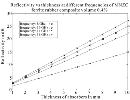
Figures 3 & 4 show the variations of reflectivity (equation 11) with frequency for different absorbing ma-terials at a thickness of 5 and 10 mm respectively. Fig-ures 5 & 6 are the plots for variations of reflectivity with thickness of layer of absorbing materials (BaFe12-2xAxCox
O19 for the tetravalent A ions, Ru4+ is chosen and ferrite-
Rubber composites with volume fraction vf = 0.4) at
dif-ferent frequencies. Reflectivity is estimated at 12GHz for various absorbing materials at different thicknesses and is presented as in Figure 7.
Reflectivity of the laminate mainly depends upon the absorption properties of the microwave absorbing mate-rial and its thickness. Thus, the microwave absorbing material, M-Type Barium ferrites exhibits excellent re-flectivity (around 20 dB better than Carbonyl-Iron parti-cle composites with volume fraction vf = 40%) over the
[image:3.595.306.535.492.684.2]entire frequency range compared to other types of ab-sorbing materials. Since attenuation constant is very high for that of M-Type Barium ferrites.
Figure 4. The variation of the reflectivity as a function of frequency for different microwave absorbers at absorber thickness of 10 mm
Figure 5. The variation of the reflectivity as a function of hickness for the BaFe12-2xAxCoxO19–copper laminate at
[image:4.595.309.536.93.263.2]dif-ferent frequencies
[image:4.595.61.287.307.469.2]Figure 6. The variation of the reflectivity as a function of thickness for the MnZn ferrite-Rubber composite-copper laminate at different frequencies
Figure 7. The variation of the reflectivity as a function of thickness for different microwave absorbers at 12 GHz fre-quency
It can also be deduced that the reflectivity of BaFe12-2x
AxCoxO19 for the tetravalent A ions, Ru4+ is chosen and
MnZn ferrite-Rubber composites with volume fraction vf = 0.4 is better by approximately 20 dB in the X-band
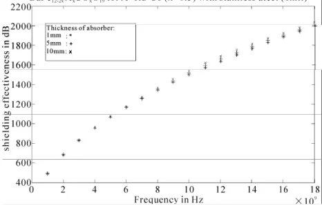
range of frequencies and it decreases at high frequencies. Investigations are carried out to determine the shield-ing effectiveness (Equation (18)) of the laminate of mi-crowave absorbing material-metal for different combina-tions of materials at different thicknesses of layers in the laminate. Figures 8 & 9 are the plots for variation of shielding effectiveness of laminate of BaFe12-2xAxCoxO19
(for the tetravalent A ions, Ru4+ is chosen) and MnZn
ferrite- Rubber composites with volume fraction vf = 0.4
for 1, 5 and 10 mm thicknesses of absorbing material and 1mil layer thickness of copper respectively. Figures 10 & 11 are the plots for variation of shielding effectiveness of laminate of BaFe12-2xAxCoxO19 (for the tetravalent A
ions, Ru4+ is chosen) and MnZn ferrite-Rubber composites
with volume fraction vf = 0.4 for 1, 5 and 10mm
thick-nesses of absorbing material and 1 mil layer thickness of stainless steel respectively.
Shielding effectiveness is also estimated for different layer thicknesses of the copper in the laminate and is presented in Figures 12 & 13 for microwave absorbing material layer of BaFe12-2xAxCoxO19 for A= Ru4+, MnZn
ferrite-Rubber composites with volume fraction vf = 0.4
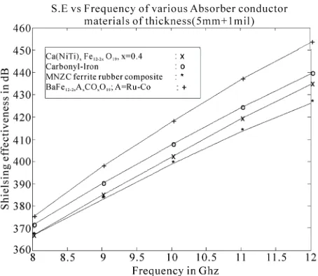
for x = 0.4 (thickness of the absorbing material = 5 mm). The plot of shielding effectiveness with frequency for different absorbing materials of the interface with copper as conducting layer material is shown in Figure 14.
[image:4.595.58.285.511.686.2]Figure 8. The variation of the Shielding effectiveness as a function of frequency of BaFe12-2xAxCoxO19–copper
[image:5.595.57.288.95.251.2]lami-nate for different thicknesses of microwave absorber
Figure 9. The variation of the S.E as a function of frequency of MnZn ferrite-Rubber composites–copper laminate for different thicknesses of microwave absorber
Figure 10. The variation of the Shielding effectiveness as a function of frequency of BaFe12-2xAxCoxO19–stainless steel
[image:5.595.305.539.298.478.2]laminates for different thicknesses of microwave absorber
[image:5.595.56.288.299.477.2]Figure 11. The variation of the Shielding effectiveness as a function of frequency of MnZn ferrite-Rubber composites– stainless steel laminate for different thicknesses of micro-wave absorber
Figure 12. The variation of the Shielding effectiveness as a function of frequency of BaFe12-2xAxCoxO19–copper for
different thicknesses of copper
[image:5.595.305.541.523.681.2] [image:5.595.55.288.537.686.2]Figure 14. Comparison of shielding effectiveness of differ-ent absorbers as a function of frequency
compared that of the absorbing material. The shielding effectiveness of the laminate using stainless steel as conducting layer is much higher than that of a laminate using copper as conducting material layer.
From the above analysis for reflectivity and shielding effectiveness, it may be deduced that laminate compris-ing of M-Type Barium ferrites as absorbcompris-ing material layer and stainless steel as conducting material layer ex-hibits very good reflectivity as well as shielding effec-tiveness characteristics. It may be concluded that the re-flectivity and shielding effectiveness primarily depend upon the material characteristics. The thickness of the material can be selected for a given application according to the requirements of the problem and subject to the availability of the materials and mechanical constraints of the circuit under consideration.
5. Acknowledgements
We thank the management of GITAM University for all
the support and encouragement rendered in this project. We also extend our thanks to the Vice Chancellor and Registrar of GITAM University for providing the re-quired facilities for carrying out this work. Our sincere thanks are also due to the Principal of GITAM Institute of Technology, Head of the Department of E.C.E and its staff for their kind support.
REFERENCES
[1] V. P. Kodali, “Engineering Electromagnetic Compatibil-ity, Principles, Measurements and Technologies,” S Chand and Company Ltd., 2000.
[2] R. B. Schulz, V. C. Plantz and D. R. Brush, “Shielding Theory and Practice,” IEEE Transactions on
Electro-magnetic Compatibility, Vol. 30, No. 3, August 1988, pp
187-201.
[3] Y. B. Feng, T. Qiu, X. Y. Li and C. Y. Shen, “Microwave Absorption Properties of the Carbonyl Iron/ EPDM Radar Absorbing Materials,” Journal of Wuhan University of
Technology Materials Science Edition, Vol. 22, No. 2,
June 2007, pp. 266-270.
[4] P. Singh, V. K. Babbar, A. Razdan, S. L. Srivastava and T. C. Goel, “Microwave Absorption Studies of Ca–Niti Hexaferrite Composites in X-Band,” Materials Science
and Engineering, Vol. 78, No. 2-3, 2000, pp. 70-74.
[5] H.-S. ChO and S.-S. Kim, “M-Hexa ferrites with Planar Magnetic Anisotropy and Their Application to High- Frequency Microwave Absorbers,” IEEE Transactions on
Magnetics, Vol. 35, No. 5, September 1999, pp. 3151-
3153.
[6] D. Y. Kim, Y. C. Chung, T. W. Kang and H. C. Kim, “Dependence of Microwave Absorbing Property on Fer-rite Volume Fraction in MnZn FerFer-rite-Rubber Compos-ites,” IEEE Transactions on Magnetics, Vol. 32, No. 2, March 1996, pp. 555-558.