The in
fl
uence of surface hardness on the fretting wear of steel
pairs
—
Its role in debris retention in the contact
J.D. Lemm
a, A.R. Warmuth
b, S.R. Pearson
b, P.H. Shipway
b,n aDivision of Materials, Mechanics and Structures, Faculty of Engineering, University of Nottingham, UK
bDivision of Materials, Mechanics and Structures and University Technology Centre in Gas Turbine Transmission Systems, Faculty of Engineering, The University of Nottingham, Nottingham NG7 2RD, UK
a r t i c l e i n f o
Article history: Received 4 July 2014 Received in revised form 2 September 2014 Accepted 4 September 2014 Available online 16 September 2014
Keywords: Fretting Steel Hardness Debris
a b s t r a c t
The influence of specimen hardness (between 275 kgf mm2and 835 kgf mm2) in an AISI Type O1 steel-on-steel fretting contact was examined. In equal-hardness pairs, a variation in the wear volume of around 20% across the range of hardnesses examined was observed. However, in pairs where the two specimens in the couple had different hardnesses, a critical hardness differential threshold existed, above which the wear was predominantly associated with the harder specimen (with debris embedment on the softer specimen surface). This retention of debris provides protection of that surface from further wear and also results in accelerated wear of the harder counterface due to abrasion by the oxide debris bed which has built up on the opposing specimen.
&2014 The Authors. Published by Elsevier Ltd. This is an open access article under the CC BY license (http://creativecommons.org/licenses/by/3.0/).
1. Introduction
Fretting wear is a unique form of material degradation caused by small amplitude oscillatory relative motion of two surfaces in contact. Fretting wear is typically encountered at relative displace-ments of less than 300mm [1]and occurs in either a gross slip regime (where there is slip displacement across the whole con-tact), or a partial slip regime (where there are parts of the contact where no slip displacement occurs). Fretting wear is experienced within a wide range of industrial sectors, including aeroengine couplings [2], locomotive axles [3]and nuclear fuel casings [4]. Under higher loads and smaller displacement amplitudes, the contact will be within the partial slip regime, often resulting in fretting fatigue where the dominant damage mode is a reduction in fatigue life[5]. Fretting in the gross slip regime generally results in larger amounts of material removal (wear) and debris forma-tion; this will be the focus of this investigation.
When analysing fretting wear, the two contacting surfaces are termedthe first-bodies, and when debris is generated within the contact, it is described as an additionalthird body. Debris can be formed from either one or both of the twofirst-bodies and is either entrapped within or ejected from the contact area. It is well documented that debris plays a key role in the fretting wear behaviour of a fretting couple[6–8]. The presence of debris may
promote wear if it is hard and acts as an abrasive or, in contrast, it may effectively separate the two first-bodies and prevent or reduce wear.
Previous research by Dobromirski has suggested that there are upwards of 50 variables that affect the fretting wear process[9], including contact pressure, temperature and surface hardness. Whilst Archard's wear equation (developed for sliding wear) has been successfully used to predict material loss in fretting [10], there are findings to suggest that the relationship between the resistance to fretting wear and material hardness is complex. Studies by Kayaba and Iwabuchi have shown that when two steels of different hardnesses were fretted against each other, the harder steel wore more than the softer contact[11]; they attributed this effect to protection of the surface by a black oxide debris layer. In their experimental programme, they used different types of steel for each of the specimens in their couple and both steels were heat treated to produce a range of hardnesses between around 200 and 800 kgf mm2; one steel had a high chromium content of around 0.9 wt% whereas the other had a chromium content o0.05 wt%. As such, it was not clear whether differences in behaviour were associated with material hardness or other changes (such as oxidation kinetics) associated with the differences in steel com-position. In similar work, Ramesh and Gnanamoorthy described the fretting behaviour of two different steels; specifically, a structural steel with differing hardness produced via heat treat-ment was fretted against a bearing steel of afixed hardness (the hardness of the bearing steel was always higher than that of the structural steel)[12]. Whilst they did not compare the wear rate of Contents lists available atScienceDirect
journal homepage:www.elsevier.com/locate/triboint
Tribology International
http://dx.doi.org/10.1016/j.triboint.2014.09.003
0301-679X/&2014 The Authors. Published by Elsevier Ltd. This is an open access article under the CC BY license (http://creativecommons.org/licenses/by/3.0/). nCorresponding author.
the structural steel and bearing steel, they saw no evidence of appreciable variation in wear rate with hardness of the structural steel (with Vickers hardness ranging from 207 to 640 kgf mm2), and concluded that the wear rate is dependent primarily on the properties of the hard oxide debris. In more recent work, Budinski [13] conducted steel-on-steel fretting tests with a hard steel against a different counterface steel; the hardness of the counter-face was varied, with its highest hardness being equal to that of the other body. A decrease in overall wear rate was observed as the hardness of the steel was decreased from its highest value until a critical value of hardness was reached, whereupon the overall wear volume significantly increased. However, the wear volumes of the two individual members of the couple were not reported.
In a similar fashion, both Varenberg et al.[6]and Elleuch and Fouvry[14,15]fretted a hard steel against a softer non-ferrous-metal; Varenberg et al. [6] fretted steel against bronze (having Vickers hardnesses of 529 and 135 kgf mm2respectively) whilst
Elleuch and Fouvry[14]fretted steel against an aluminium alloy (with Vickers hardnesses of 856 and 115 kgf mm2respectively).
Both research teams found that under certain fretting conditions, the hard steel wore substantially more than the softer counter-body, concluding that this effect is due to the formation of oxide debris which then became trapped in the contact area and embedded in the softer surface; the hard, embedded particles then abraded the harder mating steel surface, resulting in high rates of wear on the hard steel and much lower rates of wear on the softer non-ferrous counterbody.
In contrast to the researchfindings for metal–metal contacts, Endo and Marui showed that in fretting of steel against much harder ceramics, the softer steel specimen wore substantially more than the harder ceramic[16]. However, no evidence was found of hard, ceramic debris becoming embedded in the softer steel; instead, transfer of the softer steel onto the surface of the hard ceramic was observed. These results indicate that although hard-ness is a factor in fretting wear, the hardhard-ness acts primarily to influence the role of the debris which then governs the fretting wear damage.
The focus of the current work is an investigation of the role of the hardness of steel on its fretting wear behaviour. Unlike previous work on steel-steel contacts in this area [11–13], the same steel employed for both parts of the fretting couple (thus avoiding any concerns about the chemistry of the steel affecting debris formation and retention), with hardnesses of both speci-mens in the fretting couple being varied through heat treatment. Fixed fretting wear parameters (load, displacement amplitude and frequency) were employed for the majority of the tests conducted, with the only variable being hardness of the two contacting bodies; however, a small number of tests were performed with a different fretting frequency in an attempt to provide evidence to support hypotheses being developed.
2. Experimental procedure
[image:2.595.366.509.59.170.2]The steel studied in this investigation was AISI O1 steel; the composition of the steel was measured through spark emission using a WAS Foundry-Master with the results being presented in Table 1. Quenching and tempering of the steel was used to vary its
hardness. The specimens were preheated to 5001C for 30 min, austenitized at 7901C for 30 min, quenched and tempered at a selection of temperatures for 1 h. The temperatures chosen were 2401C, 4001C, 5401C and 6801C which resulted in Vickers hard-nesses of the steel (measured under a 20 kgf load) of 695 kgf mm2,
555 kgf mm2, 415 kgf mm2 and 275 kgf mm2respectively. The
hardest specimens (835 kgf mm2) were created by austenitizing
and quenching only.
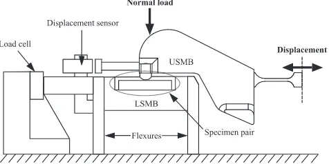
Following heat treatment of steel blanks, test specimens were machined into flat and cylindrical specimens by linear and cylindrical grinding respectively. The specimen pair was assembled in a cylinder-on-flat configuration, as shown inFig. 1. Cylindrical specimens were manufactured with a radius, R, of 6 mm and the flat specimens had a width, w, of 10 mm (this controlled the length of the line contact). The flat specimen is mounted on the lower specimen mounting block (LSMB) which is stationary and the cylindrical specimen is mounted on the upper specimen mounting block (USMB). The USMB was loaded through a dead weight configuration and the normal load that resulted is termed P, which was 450 N in the experiments reported in this paper. It is recognised that there will be very large stresses associated with the edges of the flat specimen. However, the profile in this area is expected to wear rapidly to eliminate the sharp edge; no evidence of preferential wear in this area has been observed in any of the work reported that has used this geometry or in the work that is presented in this current paper.
The main components in the rig used for the fretting experi-ments are illustrated inFig. 2. The motion of the USMB (and hence the cylindrical specimen) is created by a force generated by an electromagnetic vibrator (EMV). The displacement of the USMB is monitored by a capacitance displacement sensor which is mounted to the LSMB and is recorded throughout the duration of the test. The amplitude of the force input was controlled to achieve a set displacement amplitude of 50mm to ensure that all tests were in the gross slip regime.
[image:2.595.319.557.208.327.2]The lateral force,Q, is measured and recorded throughout the entire test by a piezoelectric load cell which is connected to the
Table 1
Measured chemical composition of AISI Type O1 Steel (wt%)
Cr C W Mn Cu V Fe
0.5 0.9 0.6 1.1 0.2 0.1 Balance
Fig. 1.Crossed cylinder-on-flat specimen configuration utilised in the fretting experiments.
[image:2.595.41.294.711.745.2]quasi-stationary LSMB. The LSMB is mounted onflexures which provideflexibility in the horizontal direction so that the majority of the lateral force is transmitted though the much stiffer load path which contains the load cell as shown in Fig. 2. Both displacement and load sensors have been calibrated (both exter-nally and in-situ) in static conditions. The load and displacement signals are sampled at a rate of two hundred measurements per fretting cycle at all fretting frequencies, with these data being used to generate fretting loops. The loops were used to derive the contact slip amplitude and the energy coefficient of friction in each cycle according to the method suggested by Fouvry et al. [17]. Average values for these were calculated for each test (the average coefficient of friction included values associated with the initial transients in the tests as suggested by Hirsch and Neu[18]).
Fretting wear tests were carried out as follows:(i) pairs where theflat and cylindrical specimens had the same hardness (termed homo-hardness pairs) were examined in fretting across the hard-ness range; (ii) flat specimens of the highest hardness (835 kgf mm2) were fretted against cylinders across the range of hardness; (iii) cylindrical specimens of the lowest hardness (275 kgf mm2) were fretted against flat specimens across the
range of hardness ((ii) and (iii) are described as hetero-hardness pairs). All tests were carried out for 105 cycles. The majority of
tests were conducted at a fretting frequency of 50 Hz with just one specimen combination being examined with a fretting frequency of 5 Hz. Tests were carried out at a relative humidity of33% and a temperature of 201C; the test parameters are summarized in Table 2.
2.1. Characterization of fretting damage
After the completion of a fretting experiment, the specimens were lightly swabbed with industrial methylated spirit to remove loose debris, thus leaving any debris that was morefirmly adhered
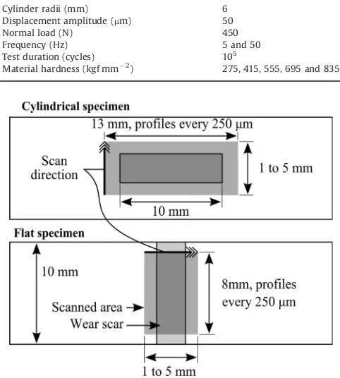
to the specimen. To evaluate their topography, the wear scars on both the flat and cylindrical specimens were scanned using a Talysurf CLI 1000 tactile profilometer. The scan areas on the flat and cylindrical specimens were as represented in Fig. 3. Wear scars on theflat specimen extended to the edge of the sample and thus it was impractical to scan the entire scar with a tactile profilometer. In these cases, to estimate the wear and transfer volumes for the entire scar, a majority of the scar was scanned, averaged and multiplied by the entire length of the scar. For both the flat and cylindrical specimens, the profiles of the surface outside the wear scars were used to create (by interpolation) a reference surface (representing the surface profile of the whole surface before wear occurred), as proposed by Elleuch and Fouvry [15] and illustrated inFig. 4. The volume below each reference surface (a negative volume) was regarded as lost material and the volume above it (a positive volume) was regarded as transferred material. The total net wear volume,Vw, is as defined in Equation 1.
Vþ¼VFlatþ þVCylinderþ ð1aÞ
V¼VFlat þVCylinder ð1bÞ
Vw¼ ðVþþVÞ ð1cÞ
Scanning electron microscopy (SEM) was performed (using a Phillips XL30 microscope) to ascertain the nature of the wear scars and compare the nature of oxide formation and retention. Back-scattered electron imaging (BSE) was used at 20 kV to distinguish the oxide within the scar from the metallic background; energy-dispersive X-ray (EDX) analysis was also performed within the SEM. Additionally, X-ray diffraction (XRD) using a Siemens D500 diffractometer was utilised to characterise the debris ejected from the contact during fretting.
3. Experimental results
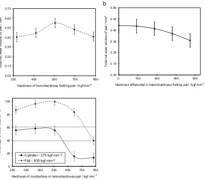
The values of total net wear volume (Vw—see Eqs. (1a)–(c))
from the homo-hardness tests are shown inFig. 5(a). The error bars plotted are the mean of the total net wear volume variance over all the tests conducted in this study. The total net wear volume remains similar across the hardness range examined; however, the total net wear volume from the tests with specimens with hardness of 555 kgf mm2 were the highest of all those
[image:3.595.311.540.58.211.2]examined. A small amount of wear volume bias was observed when the wear volume on the cylindrical andflat specimens for these tests were compared; across the range of hardness, theflat specimen typically accounted for40710% of the total net wear volume with the remaining60710% being accounted for by the cylindrical specimen.
Table 2
Summary of the fretting test parameters.
Cylinder radii (mm) 6
Displacement amplitude (mm) 50
Normal load (N) 450
Frequency (Hz) 5 and 50
Test duration (cycles) 105 Material hardness (kgf mm2
) 275, 415, 555, 695 and 835
Fig. 3.Illustration of the areas profiled on both theflat and cylindrical fretting specimens.
Ref. Surface
Material lost (
V
-)
Material transferred (
V
+)
[image:3.595.37.278.457.725.2]The energy coefficient of friction for the homo-hardness fretting pairs is presented as a function of hardness inFig. 6. It can be seen that the coefficient of friction was highest for the softest pair and decreased monotonically as the specimen hardness increased. It should be noted
that the values of the energy coefficient of friction for the hetero-hardness fretting pairs all lay within this range. The change in coefficient of friction results in changes in the slip amplitude (the displacement amplitude is maintained at 50mm, but the slip ampli-tude is less than this, with the remnant being associated with elastic deformation between the contact and the point where the displace-ment is measured). Examination of the fretting loops for the tests with the lowest coefficient of friction indicate a slip amplitude of41mm, with the slip amplitude for the tests with the highest coefficient of friction being 39mm. The magnitude of this change indicates that the coefficient of friction (and any associated changes in true slip amplitude) is not a dominant influence on the behaviour of these contacts.
As described, a number of specimen combinations were examined where (in some cases) there was a difference in hardness between the cylindrical and flat specimen. For all the combinations examined, the total net wear volume (Vw) was taken and grouped according to the difference in the hardness between the two specimens; for each hardness difference, the average of the total net wear volumes (Vw)
were plotted against the hardness difference as presented inFig. 5(b). It can be seen that as the difference in hardness between the two samples of the pair increased, the total net wear volume of the pair decreased.
Fig. 5(c) is a plot of the components of the wear as a fraction of the total net wear volume associated with each of the specimen for two
Total net wear volume of pair / mm
3
0.00 0.10 0.20 0.30 0.40 0.50 0.60
0 150 300 450 600
Hardness differential in heterohardness fretting pair / kgf mm-2 0.00
0.10 0.20 0.30 0.40 0.50 0.60 0.70
250 400 550 700 850
Total net wear volume of pair / mm
3
Hardness of homohardness fretting pair / kgf mm-2
0 20 40 60 80 100
250 350 450 550 650 750 850
Percentage of wear volume / %
Hardness of counterface in heterohardness pair / kgf mm-2 Cylinder - 275 kgf mm
Flat - 835 kgf mm
[image:4.595.97.515.56.423.2]-2 -2
Fig. 5.(a) Total net wear volume (Vw
) of homo-hardness fretting pairs as a function of specimen hardness; (b) total net wear volumes (Vw
) for all fretting pairs examined as a function of hardness difference between the specimens; (c) distribution of the wear volume between the specimens (fraction of the total net wear volume) for the cases when theflat specimen was the hardest (835 kgf mm2
) and when the cylindrical specimen was the softest (275 kgf mm2
) when fretted against the counterbodies across the range of hardnesses. Also shown are the lines representing the general wear bias observed in the homo-hardness tests, where the ratio between the cylinder andflat wear volume was observed to be60:40 in all cases.
0.00 0.10 0.20 0.30 0.40 0.50 0.60 0.70 0.80 0.90
250 400 550 700 850
Energy coefficient of friction
[image:4.595.53.286.488.671.2]Hardness of homohardness fretting pair / kgf mm-2
cases; (i) the fraction of wear associated with the soft (275 kgf mm2) cylindrical specimen being fretted againstflat
speci-mens across the range of hardness; (ii) the fraction of wear associated with the hard (835 kgf mm2)flat specimen being fretted
against cylindrical specimens across the range of hardness. For tests that were conducted with a hardflat specimen with cylinders across the range of hardness, it can be seen that when the cylindrical specimen had a hardness of 695 kgf mm2and below, the majority
(480%) of the wear occurred on the hardflat specimen. However, when the cylinder hardness was further increased to 835 kgf mm2,
the wear on the hardflat specimen rapidly dropped to40% of the total. For the fretting combinations with the soft (275 kgf mm2)
cylindrical specimens, it can be seen that the wear of the cylindrical specimen consistently made up60% of the total wear volume for all of the hardnesses of theflat counterbody between 275 kgf mm2
and 555 kgf mm2; however, as the hardness of theflat counterbody was increased further, the wear volume of the soft cylinder was substantially reduced and the wear of the hard flat counterface dominated. It should be noted that due to the nature of the results in thisfigure, the wear data for the 835 kgf mm2flat fretted against a
275 kgf mm2cylinder were included in both data series.
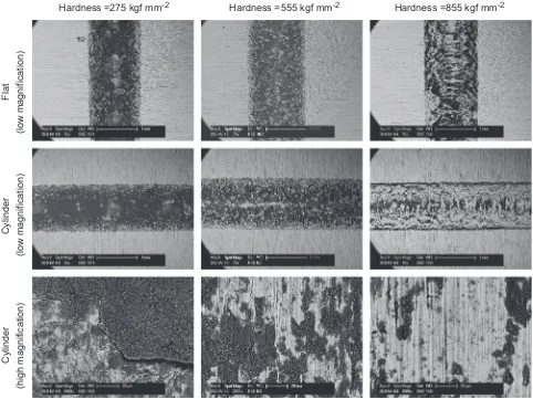
Fig. 7shows BSE micrographs of both specimens (cylinder andflat) of the homo-hardness fretting pairs for three of the hardnesses examined. The wear debris formed is made up of a mixture of metallic particles and oxide, and due to its high oxygen content (as demon-strated by EDX analysis), it appears darker in BSE micrographs. It can be seen that the level of oxide retention is similar for both the cylinder
andflat specimens within each of the specimen pairs. Also, it can be seen (from the high magnification images) that the morphology of the retained debris in each case is very similar. However, as the hardness of the specimens increased, the quantity of darker oxide debris retained in the wear scar was clearly reduced. Moreover, the debris appeared to have embedded into the surface of the softest steel (as seen from the high magnification image of the cylindrical specimen); in contrast, the high magnification images of the scar surfaces in the highest hardness steel show no evidence for debris embedment, and instead show only ploughing marks and very little debris retention.
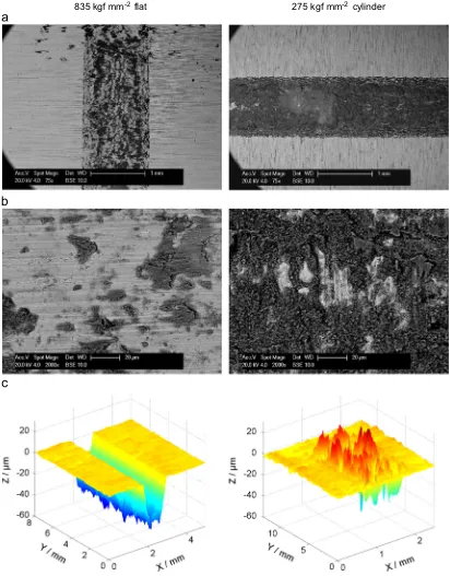
Figs. 8 and 9present information regarding the wear surfaces from a hard (835 kgf mm2) flat versus soft (275 kgf mm2)
cylinder specimen combination, withFig. 8presenting information following fretting at 50 Hz, and Fig. 9 presenting the same information following fretting at 5 Hz. After fretting at 50 Hz, the micrographs inFig. 8(a) indicate considerably more oxide debris retention on the softer cylindrical specimen than on the hardflat specimen. The average coefficient of friction for the couples fretted at both 50 Hz and 5 Hz was 0.73.
Fig. 8(b) indicates that (again) there is little evidence of oxide debris embedding into the hard surface, whereas there is some evidence to indicate that such embedding into the softer surface does occur (although this evidence is not clear due to the high levels of debris coverage on the softer specimens). Fig. 8 (c) illustrates the wear scar topography on both the hardflat and soft cylindrical samples. The geometrical form of the cylindrical specimen has been removed to facilitate direct comparison with the
Hardness =275 kgf mm
-2Hardness =555 kgf mm
-2Hardness =855 kgf mm
-2Cylinder
(high magnification)
Cylinder
(low magnification)
Flat
[image:5.595.52.534.355.716.2](low magnification)
worn profile on theflat specimen. The wear scar topography of the hardflat specimen shows a deep (U-shaped) wear scar; in contrast, the soft cylindrical specimen exhibits a surface with multiple peaks (along with some material removal), indicating that debris material has been deposited and retained on this surface.
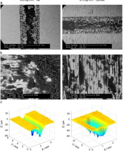
Fig. 9relates to the same specimen combination, but following fretting which has taken place at 5 Hz. In thisfigure, it is clearly visible that less debris retention has occurred on the soft cylind-rical specimen in comparison to the experiments conducted at 50 Hz (Fig. 8); similar levels debris retention are observed in the centre of the contact, but much less debris is retained towards the outer edges of the contact. In contrast, for the experiments
conducted at 5 Hz on the hard flat specimens, the centreline of the contact has a higher level of debris retention which was not observed following fretting at the higher frequency (Fig. 8).Fig. 9 (c) illustrates the surface topography of the two specimens following fretting at the lower frequency; whereas the soft cylindrical specimen following fretting at 50 Hz (shown inFig. 8 (c)) shows a significant amount of debris build-up on the surface, the surface of the soft cylinder following fretting at 5 Hz shows a large trough indicating that there has been significantly more wear with only limited debris retention.
A substantial amount of debris was ejected from the contact zone from all tests. The debris appeared visually to be made up of
[image:6.595.96.508.60.587.2]835 kgf mm
-2flat
275 kgf mm
-2cylinder
Fig. 8.Characterisation of surface damage on both specimens following fretting at 50 Hz of a hard (835 kgf mm2
)flat versus a soft (275 kgf mm2
afine grey and red-brown powder. XRD was used to categorise the debris. Diffraction peaks from the debris showed strong matches for both Fe2O3 (haematite) and metallic iron but no other iron
compounds could be identified.
4. Discussion
4.1. The effect of hardness in homo-hardness fretting pairs
It is apparent from the SEM and profilometry that changing the hardness of a material has a significant effect on the fretting wear
behaviour in certain circumstances, but has little effect in others. When analysing the homo-hardness fretting pairs, it is clear (Fig. 5(a)) that changing the hardness had very little effect on the total net wear volume of the specimens. Changing the hard-ness of the homo-hardhard-ness pairs also had little influence over which specimen (flat or cylindrical) component wore more. Across all homo-hardness pairs, oxidised debris was present both in the contact and ejected from the contact. It appears that by increasing the hardness of the specimens, the amount of debris adhered to the surface is reduced (seeFig. 7). It should be noted that although there are some variations in slip amplitude (as opposed to the applied displacement amplitude which was held constant at
[image:7.595.83.503.66.583.2]835 kgf mm
-2flat
275 kgf mm
-2cylinder
Fig. 9.Characterisation of surface damage on both specimens following fretting at a low frequency of 5 Hz of a hard (835 kgf mm2
50mm) associated with differences in coefficient of friction (values of slip amplitude varied between 41mm and 39mm), the wear scars all exhibited a semi-width of more than 500mm by the end of the test, indicating that with these slip amplitudes, a significant majority of the contact remained covered throughout the test in all cases. The medium hardness (555 kgf mm2) pairs wore 20%
more than the average of the other homo-hardness pairs. This higher wear volume at an intermediate hardness may result from two opposing influences; at hardnesses below555 kgf mm2, it
is proposed that the oxidised debris acts primarily to protect the metal from abrasive wear, with the level of debris retention (and thus also the level of protection) increasing as the specimens become softer. This results from an increased tendency for the oxide debris to embed into the softer surfaces, and thus be retained in the contact more easily (this hypothesis is supported by the reduction in oxidised debris retained in the contact with increasing hardness as observed inFig. 7). As hardnesses increased above555 kgf mm2, it is proposed that another effect begins to
dominate. It is proposed that as the hardness increases, the wear volume decreases simply due to the wear relationship that Arch-ard had previously defined, namely that increased hardness will result in an increased wear resistance.
4.2. The effect of hardness in hetero-hardness fretting pairs
A difference in hardness between the two specimens in a hetero-hardness fretting pair results in a change in the total net fretting wear volume, which generally decreased as the hardness difference increased as illustrated inFig. 5(b). Whilst this change was significant (30% reduction in total net fretting wear at the highest hardness difference), perhaps more significant was the change in the distribution of the wear between the two specimens in these cases. In both of the cases examined in detail (Fig. 5(c)), the wear was seen to be more pronounced for the harder speci-men as the difference in hardness between the two specispeci-mens making up the fretting contact exceeded a critical value. In the experiments where the hardflat specimens were fretting against softer cylinders, dominance of wear in the harder specimen was observed even for the smallest hardness differential (with the 695 kgf mm2cylinder), and this was maintained as the hardness
differential increased. For the fretting of the softest cylinder against harderflat specimens, the wear was 60/40 distributed between the specimens (as observed for homo-hardness pairs) for cases with flat specimens of hardness up to and including 555 kgf mm2; for flat specimens with higher hardness
(695 kgf mm2 and 835 kgf mm2), the wear of the hard flat
specimen dominated.
Following BSE examination of the wear scars, it is clear that debris retention is also influenced by the change in specimen hardness (for both homo- and hetero-hardness pairings). The softer specimens generally exhibited large amounts of embedded oxide debris in the wear scars, whereas the scars in the harder specimens appeared to be primarily metallic with a smaller amount of oxide retention. It is proposed that the oxide debris is retained on the softer samples due to physical roughening and (subsequently) indentation and keying of the debris layers into these softer surfaces; the retained debris protects the underlying metal from wear (since it is keyed into the surface) and promotes wear on the harder specimens as it abrades against it (this mechanism operates most effectively for the fretting pairs with a hardness difference between the samples). This is in contrast to the mechanisms of wear relating to the harder specimens, where the metallic surface resists plastic deformation, thus hindering debris retention onto the surface by physical keying. This poor debris retention leaves the metallic surface exposed to abrasion by any oxidised debris retained on an opposing softer counterbody, and clear evidence of such abrasion is shown via the ploughing marks
which are prevalent on the surfaces of hard specimens following abrasion (Fig. 7andFig. 8).
The behaviour of debris within a fretting contact is known to be complex, and has been shown to depend upon a number of factors. Pearson et al.[19]proposed that even small increases in ambient temperature (to 851C) could result in a change in the sintering behaviour of the debris in the fretting contact and Warmuth et al. [20]have shown that fretting frequency affects debris retention in the contact through both temperature and kinematic effects. In the current work, in an attempt to further understand the behaviour of the debris in a hetero-hardness contact, the investigation of the behaviour of the contact made up from the hardestflat specimen and the softest cylindrical specimen was extended from fretting at 50 Hz (shown in Fig. 8) to fretting at 5 Hz (shown in Fig. 9). Comparison of the SEM images and profilometry inFigs. 8 and 9 indicate that the wear behaviour of the soft sample (in particular) was very different at the two fretting frequencies. With a fretting frequency of 5 Hz, both the hard and the soft specimen formed a deep wear scar, whereas at 50 Hz, only the hard sample experi-enced significant wear, with the softer sample exhibiting debris retention on the wear surface. The hard samples in the tests conducted at both 5 Hz and 50 Hz had almost identical wear scars in terms of depth and volume. The BSE microscopy showed a reduced build-up of oxidised debris on the soft specimen at the lower fretting frequency; this may result from the lower tempera-ture experienced in the contact as the fretting frequency is reduced (reduced frictional power input) leading to an increase in the hardness of the softer surface or to a reduced tendency for sintering of the fretting debris, both of which would promote debris loss from the contact. However, the sintering referred to here must not be confused with the more general high-temperature sintering associated with glaze formation. Whilst the higher temperature (associated with fretting at the higher frequency) does result in the retention of the debris within the contact, the morphology of the surface of the debris layer on the soft sample inFig. 7shows none of the smoothness expected from a glaze. In addition, the coefficient of friction associated with the higher frequency fretting (debris-retaining) was the same as that observed for the same pair fretted at a lower frequency (being 0.73 in both cases), which is in contrast to the effects observed in fretting of a steel-steel pair, where the coefficient of friction was observed to decrease as the temperature was increased[19].
5. Conclusions
Fretting wear has been examined in gross sliding conditions between specimens made of the same steel, but with hardness being varied via heat treatment. The fretting configuration employed was that of a cylinder-on-flat contact with a fretting frequency of 50 Hz. It has been shown that when the two speci-mens are of the same hardness, there is only a small variation in total net fretting wear volume across the range of hardnesses examined (from 275 kgf mm2 to 835 kgf mm2). It was also
shown that the cylindrical specimen exhibited a slightly higher wear volume than theflat specimen (in the ratio 60:40).
protection of the softer specimen (and a reduced wear volume) and preferential wear of the harder specimen. In the most extreme cases, more than 95% of the total wear volume was associated with the harder specimen in a pair.
Experiments also point to the fact that debris retention in the contact (or removal from the contact) is a complex phenomenon, which is not simply controlled by specimen hardness. With the most extreme hardness differential between the specimens (aflat specimen with a hardness of 835 kgf mm2 mated against a
cylindrical specimen with a hardness of 275 kgf mm2), it was
shown that at a fretting frequency of 50 Hz, the softer cylinder exhibited very little wear, with debris adherence to the wear scar dominating (significant wear of the harder flat specimen was observed). However, on reducing the fretting frequency to 5 Hz, both the hard and soft specimens were observed to suffer significant wear. The accelerated wear on the softer specimen was linked to a reduction in the ability for debris to be effectively retained within the fretting contact, and it is proposed that this difference is associated with changes in the temperature in the contact associated with the reduced fretting frequency, which will lead to increases in hardness of the surfaces and a reduction in the tendency for the debris to sinter into a coherent bed within the contact.
Acknowledgements
The authors wish to thank the Taiho Kogyo Tribology Research Foundation, Toyota City, Japan for supporting an upgrade of the experimental facilities which have underpinned this work. The views expressed in this paper are those of the authors and not necessarily those of the Taiho Kogyo Tribology Research Foundation.
References
[1]Budinski KG. Guide to Friction, Wear, and Erosion Testing: (MNL 56). ASTM
International; 2007.
[2]Leen S, Hyde T, Ratsimba C, Williams E, McColl I. An investigation of the
fatigue and fretting performance of a representative aero-engine spline
coupling. J Strain Anal Eng Des 2002;37:565–83.
[3]Zheng JF, Luo J, Mo JL, Peng JF, Jin XS, Zhu MH. Fretting wear behaviors of a
railway axle steel. Tribol Int 2010;43:906–11.
[4]Lee Y-H, Kim H-K. Fretting wear behavior of a nuclear fuel rod under a
simulated primary coolant condition. Wear 2013;301:569–74.
[5]Vingsbo O, Söderberg S. On fretting maps. Wear 1988;126:131–47.
[6]Varenberg M, Halperin G, Etsion I. Different aspects of the role of wear debris
in fretting wear. Wear 2002;252:902–10.
[7]Ding J, McColl IR, Leen SB, Shipway PH. Afinite element based approach to
simulating the effects of debris on fretting wear. Wear 2007;263:481–91.
[8]Ding J, Leen SB, Williams EJ, Shipway PH. A multi-scale model for fretting wear
with oxidation-debris effects. Proc Inst Mech Eng Part J: J Eng Tribol 2009;223:
1019–31.
[9]Dobromirski J. Variables of fretting process: Are there 50 of them? ASTM
International; 1992.
[10]McColl IR, Ding J, Leen SB. Finite element simulation and experimental
validation of fretting wear. Wear 2004;256:1114–27.
[11]Kayaba T, Iwabuchi A. Effect of the hardness of hardened steels and the action
of oxides on fretting wear. Wear 1981;66:27–41.
[12]Ramesh R, Gnanamoorthy R. Effect of hardness on fretting wear behaviour of
structural steel En 24, against bearing steel, En 31. Mater Des 2007;28:1447–52.
[13]Budinski KG. Effect of hardness differential on metal-to-metal fretting damage.
Wear 2013;301:501–7.
[14]Elleuch K, Fouvry S. Experimental and modelling aspects of abrasive wear of a
A357 aluminium alloy under gross slip fretting conditions. Wear 2005;258:40–9.
[15]Elleuch K, Fouvry S. Wear analysis of A357 aluminium alloy under fretting.
Wear 2002;253:662–72.
[16]Endo H, Marui E. Studies on fretting wear (combinations of various ceramics
spheres and carbon steel plates) Wear 2004;257:80–8.
[17]Fouvry S, Duó P, Perruchaut P. A quantitative approach of Ti-6Al-4V fretting
damage: Friction, wear and crack nucleation. Wear 2004;257:916–29.
[18]Hirsch MR, Neu RW. A simple model for friction evolution infretting. Wear
2013;301:517–23.
[19]Pearson SR, Shipway PH, Abere JO, Hewitt RAA. The effect of temperature on
wear and friction of a high strength steel in fretting. Wear 2013;303:622–31.
[20]Warmuth AR, Shipway PH, Sun W. Fretting wear mapping: The influence of
contact geometry and frequency on debris formation and ejection for a