http://www.scirp.org/journal/wjet ISSN Online: 2331-4249
ISSN Print: 2331-4222
Temperature and Flow Rate Control of
Diffusing Chamber
Yongbo Lai, Guoping Lu, Zhiwei Wang
School of Mechanic & Electrical Engineering, Jiangsu College of Information Technology, Wuxi, China
Abstract
The temperature and flow rate control of diffusing chamber is one of the key technologies in the production of poly-crystal silicon thin film. As there exist some modeling uncertainties and errors in the actual system, it is difficult to guarantee the chamber variable temperature conditions and the flow rate of diffusion gas being controlled within its targeted range in the rapid thermal processing (RTP). In this paper, the control applies the programmable logic controller (PLC) to configure control hardware system, proposes expert pro-portional integral derivative (PID) control method to regulate the gas flow rate and H∞ control strategy to attenuate chamber modeling uncertainties and disturbances, respectively, to steer the chamber rapid variable tempera-ture very close to the expected product temperatempera-tures. Furthermore, it designs human-machine integrated user control interface (HMI) and achieves rapid and accurately control performances for user operating production. The signed control system are simulated and tested in the application, which de-monstrates that the control method has strong robustness when the modeling uncertainties, errors, parameters perturbation and disturbances, the tempera-ture and flow rate meet the requirements of precisely trajectory following.
Keywords
Diffusing Chamber, PLC Hardware Configuring, Expert PID Control, H∞ Control, HMI
1. Introduction
The poly-crystal silicon thin films have excellent photo-electric properties and production of low cost in the field of energy and informational industry, become a very important electronic materials, widely used in the integrated circuits, semiconductor devices and solar energy cells production. The manufacturing technique includes oxidation, diffusion, alloy and etc. [1] [2], in the diffusion How to cite this paper: Lai, Y.B., Lu, G.P.
and Wang, Z.W. (2017) Temperature and Flow Rate Control of Diffusing Chamber. World Journal of Engineering and Tech-nology, 5, 58-76.
https://doi.org/10.4236/wjet.2017.51006
Received: December 2, 2016 Accepted: February 18, 2017 Published: February 21, 2017
Copyright © 2017 by authors and Scientific Research Publishing Inc. This work is licensed under the Creative Commons Attribution International License (CC BY 4.0).
http://creativecommons.org/licenses/by/4.0/
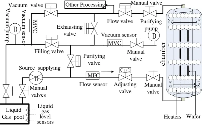
process, the diffusing chamber is an important equipment for diffusion gas sup-plying and reacting, and its temperature and flow rate control are the key tech-nologies for poly-crystal silicon thin film production. One kind of overall struc-ture of diffusing chamber control devices is shown as Figure 1.
The diffusing chamber is axis symmetric and separates the inner part, which contains the deposited wafers and the diffusion gas, and the lamp heaters are uniform annular which distributed on the inner part; also the chamber inter-nal wall is coated with reflective layer. The deposited wafers are partitioned into concentric elements and are coaxial with the chamber. The temperature is sensed at twelve locations across the wafers along the cylindrical axis of the chamber.
In the production, the chamber temperature should be easily operated with given control parameters of the gas temperature and flow rate, and its product process satisfies the following technical requirements:
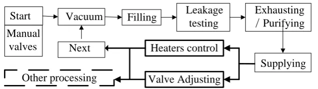
1) The diffusing chamber is vacuum condition before ventilating diffusion gas;
2) To ensure the purity of the diffusion gas, the ventilating pipelines and chamber need purify after an operating cycle, meanwhile, it satisfies the function of gas automatic to be replenished in the production;
3) Achieving rapid variable temperature and flow rate adjustment, satisfying the technical indicators of poly-crystal silicon thin film production;
4) The control process of all the electric actuators can be operated with ma-nual and automatic control modes, and the control processes are conveniently, safety and reliable for user operating.
In Figure 1, it is a difficult control system that there are two control targets
chamber
Vacuum pump
Liquid
Gas pool
Manual
valves
Liquid
gas
level
sensors
Filling valve
D
Purifying
pump
Flow valve
Vacuum valve
Source supplying
Purifying
valve
Exhausting
valve
Flow sensor
Adjusting
valve
Manual
valve
D
Manual valve
Manual
valve
D
D
MFC
MVC
MVC
Vacuum sensor
Heaters
Vacuum sensor
Other Processing
Wafer
Z
=
0
Z
=
1
Z
=
1
Z
=
[image:2.595.143.527.468.706.2]0
and two complex coupling variables with modeling uncertainties, errors and disturbances. There is a need to develop a mathematical model that takes into accounts the combined dynamics of diffusion gas flow rate and heaters power, and a method for high-performance rapid variable temperature control with strong robustness. For the chamber control theory and application, there were many results in the past few decades [3]-[11], such as using traditional PID con-trol method to solve the temperature tracking in [3]; by using linear program-ming techniques, Norman [4] formulated and solved the problem of minimizing the worst error in the wafer temperature control. To ensure deposited wafer temperature trajectory tracking, model-based control presented in [6] [7] [8], but these control methods were based on the exact mathematical modeling, therefore, they may not be applicable in an actual rapid thermal processing sys-tem in the presence of modeling uncertainties, disturbances, errors and etc.. To overcome the modeling errors, Lai and Lin [9] applied neural fuzzy network to temperature control in a rapid thermal processing system, then, Jin and Hyun [10] proposed a neural network iterative learning controller to compensate the mathematical model errors, and achieved an accurate output tracking by expe-riment and simulation. Based on iterative learning control, Yang et al. [11] de-signed a quadratic-optimal learning control method and implemented on an experimental RTP system despite existed disturbances and model errors.
Recently, scholars and engineers have presented some novel control tech-niques for thermal processing in the industry application [12] [13] [14] [15]. Based on BP and GA technologies, Zhang et al. [12] reduced the static tempera-ture compensation and temperatempera-ture drift. Li et al. [13] used a novel state space model predictive method to solve the industrial furnace temperature control. For dynamic temperature compensation, Qiao and Chai [14] proposed an intel-ligence-based temperature switching control implemented in the raw meal pro-duction. To eliminate the coupling effect, an intelligent PID decoupling control system integrating self-growing radial basis function neural network was pro-posed in [15]. Compared with the aforementioned results, based on PLC hard-ware configuring, this paper designs the H∞ variable temperature control and Expert PID flow rate control in the diffusing chamber; the temperature control synthesizes their advancements in the static temperature drift and dynamic dis-turbances attenuation, meanwhile, the system modeling uncertainties, errors and unknown disturbances are adequately considered. Through numerical simula-tions and actual application, it demonstrates that the present control strategy is effective.
The remaining parts of this paper are organized as follows:
Manual
valves
Start
Leakage
testing
Exhausting
/
Purifying
Supplying
Next
Valve Adjusting
Heaters control
Vacuum
Filling
[image:4.595.213.532.70.159.2]Other processing
Figure 2. The production control flow chart.
system performances are simulated and analyzed in the actual production.
Notations: The notation used throughout the paper is fairly standard. n
R
and n m×
R denote the n-dimensional Euclidean space and the set of all n × m
real matrices, respectively; I is the identity matrix with appropriate dimension. The superscript T represents the transpose of a matrix; X refers to Euclidean
norm of the vector X. The notation P > 0 means that P is real symmetric and positive definite. In symmetric block matrices, the ∗ asterisk represents a term that is induced by symmetry. Matrices, if their dimensions are not explicitly stated, are assumed to be compatible for algebraic operations.
2. System Control Hardware Design
2.1. System Control Hardware Configuring
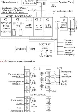
In accordance with the system devices (Figure 1) and the flow chart (Figure 2), the temperature and flow rate control have 4 analogues and 6 digital input sig-nals, respectively, with the additional 28 output control signals. The system hardware control main modules applies a compacted Siemens PLC (CPU 314 C-2 DP) [16], affiliates 2 digital input/output (DI/DO) modules (C1_2 and C2), one analogue/digital (AI/DI) signals input module (C_1), one power module and one HMI (MP277 10#) to configure; The system control hardware confi-guring satisfies the control output of the valves, pumps, power driving boards and heaters, the construction of system control hardware is shown in Figure 3.
2.2. The Hardware’s Input and Output (I/O) Ports Definition
According to Figure 3, defining the I/O ports function of the module C1_1, C1_2 and C_2 are shown in Figures 4-6, respectively.
2.3. Temperature Sampling and Driving Circuit Design
MPI DP MPI/RS232 COM
MP277 10'
HMI
L+ M 24V GND 24VDC-5A Power Module 6ES7-307.
.
.
12 AD 590 s 12 Analog sample channels.
2 vacuum pressure sensors Flow sensor Liquid gas sensors 12C0
C1
C2
12
6ES7314-6CG03-0AB0
16 DO ModuleC1_1
C1_2
16 DI/ 16 DO Module AI/DI Module 9 AI0+AI0-
CPU314C-2DP
Supplying / Filling / Pumps / Exhausting / Purifying / Alarm / Horn/ DC power
12 power driving boards 12 Power heaters
4 addresses coding Adjusting Valve
[image:5.595.211.529.69.309.2]Emergency
Figure 3. Hardware system construction.
Emergency stop Chain input 1 2 3 4 5 6 7 8 9 10 11 12 13 14 15 16 17 18 19 20 21 22 23 24 25 26 27 28 29 30 31 32 33 34 35 36 37 38 39 40 V
A CH0AI
V A CH1AI
V A CH2AI
V A CH3AI
AI AD590
V A CH0AO V A CH1AO
C1_1
DI2.0 DI2.1 DI2.2 DI2.3 DI2.4 DI2.5 DI2.6 DI2.7..
..
.
24V0 GND0 Liquid levels Vacuum pressure sensor 1 Vacuum pressure sensor 2 Flow sensor 314 6CG03-0AB0 AI0+ AI0-Thermocouple signalFigure 4. Module C1_1 I/O ports function.
3. System Control Strategy and Program Design
In this section, the system control strategies and program flow chart design will be presented. The system adopts manual and automatic operating modes in terms of the requirements of production process, this paper only presents the automatic control mode design.
3.1. System Program Flow Design
[image:5.595.213.532.77.532.2]1 2 3 4 5 6 7 8 9 10 11 12 13 14 15 16 17 18 19 20 21 22 23 24 25 26 27 28 29 30 31 32 33 34 35 36 37 38 39 40
C1_2
DO0.0 DO0.1 DO0.2 DO0.3 DO0.4 DO0.5 DO0.6 DO0.7.
.
.
.
GND0 314 6CG03-0AB0 DI0.0 DI0.1 DI0.2 DI0.3 DI0.4 DI0.5 DI0.6 DI0.7 DI1.0 DI1.1 DI1.2 DI1.3 DI1.4 DI1.5 DI1.6 DI1.7 DO1.0 DO1.1 DO1.2 DO1.3 DO1.4 DO1.5 DO1.6 DO1.7 24V0.
.
.
SSR1 SSR2 SSR3 SSR4 SSR5 SSR6 SSR7 SSR8 SSR9 SSR10 SSR11 SSR0.
.
.
24V0 GND0 GND0 GND0 ADD3 ADD2 ADD1 [image:6.595.265.482.73.290.2]ADD0 coding for analogue sampling 12 outputs for heaters GND0 24V0
Figure 5. Module C1_2 I/O ports function.
1 2 3 4 5 6 77 8 9 10 11 12 13 14 15 16 17 18 19 20
C2
.0 .1 .2 .3 .4 .5 .6 .7 322 1HH01-0AA0..
.
.
24V0 24V0.
..
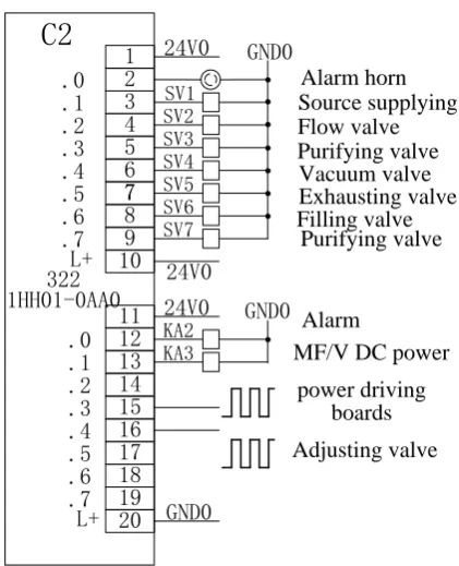
SV1 SV2 SV3 SV4 SV5 SV6 SV7 GND0 Alarm horn Source supplying Flow valve Purifying valve Vacuum valve Exhausting valve Filling valve Purifying valve L+ .0 .1 .2 .3 .4 .5 .6 .7 L+ 24V0 GND0.
KA2 KA3 GND0 AlarmMF/V DC power power driving
boards Adjusting valve
Figure 6. Module C2 I/O ports function.
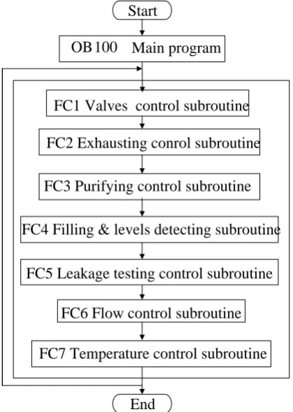
the designed main control program flow include temperature and flow rate analogue detecting control, Modbus communication, valves control, heating control, exhaust purifying, leakage testing and diffusion gas filling subroutine modules, the systems applies circular scanning output to carry out work, the main program flow chart is shown in Figure 8.
3.2.
Temperature Interrupt H∞ Control
[image:6.595.267.478.321.581.2]Vcc 24
MC
74
HC
4514
N
VDD
GND
Y0 Y1 Y2 A0
Y3 Y4 Y5 Y6 Y7 Y8 Y9 Y10
Y14 Y11 Y12 Y13
Y15 A1
A2
A3
LE
CS
ADD0 2
ADD1 3
ADD2 21
ADD3 22
DGND 23 Vcc 1
DGND C1_1
Isolation amplifier
AIO-AIO+
11 SRA0 9 SRA1
19 SRA11
1KΩ
12
AD
590
s
.
.
.
.
.
...
10
[image:7.595.264.484.74.300.2]20
Figure 7. Temperature sampling & driving circuit.
FC1 Valves control subroutine
FC7 Temperature control subroutine
FC2 Exhausting conrol subroutine
FC3 Purifying control subroutine
FC5 Leakage testing control subroutine
FC6 Flow control subroutine
FC4 Filling & levels detecting subroutine
OB100
Main program
Start
End
Figure 8. Main control flow chart.model of the diffusing chamber is
( )
( )
( )
( )
(
)
1
dis
dis gas wafer 0 dis
, ,
,
Q
Q Q
T t z T t z
C P t Q
t z
Q Q C Q C εS T T t z Q
−
∂ ∂
+ = −
∂ ∂
= + + − + ∆
[image:7.595.277.487.335.630.2]where T t z
( )
, is the temperature distributing vector of internal chamber, CQis the parameter of heat capacity matrix, ε is the coefficient matrix of heat conduction for the chamber’s internal and external temperatures and S is heat transfer area. t≥t0, 0≤ ≤z 1, T0 is the external temperature of chamber,
( )
, 0( )
T t =T t is the condition of temperature boundary values, T t z
( )
, =T t0( )
0is the initial temperature. P t
( )
is the heaters output power. Qdis is thesys-tems’ synthetic diffusing heat energy, in which Qgas is the diffusion gas
ab-sorbed heat energy,
( )
gas gas
Q = f t × ×T J (2)
where f t
( )
is the diffusion gas flow rate, Jgas is the diffusion gas specificheat capacity. Qwafer is the radiation heat energy absorbed by the wafer and
wafer wafer
Q =ρ × ×m T (3)
where ρwafer and m are the wafer specific heat capacity parameter and mass,
respectively. ∆Qdis= ∆ ×J T is the unknown heat energy and ∆J is the norm
bounded uncertainties which can be depicted the following,
( )
J HF t E∆ = (4)
where H and E are known constant matrices, F t
( )
is the Lebesgue measurabletime varying matrix and satisfies
( ) ( )
TF t F t ≤I (5)
Considering the actual structure of chamber and the heating mode in Figure 1, the inner wall of chamber is assumed as a gray, diffuse, opaque surface, the heat absorbed of all the wafer elements is also assumed to be equal, which can be thought the temperature distribution is uniform of the inner part of chamber, that is
( )
, 0T t z
z
∂
=
∂ (6)
Assuming Y t
( )
=T t( )
is the measured temperature, then the dynamicmod-el (1) is simplified to
( )
( )
(
)
( )
( )
1
0 gas wafer dis
d
d Q Q Q
T t
C P t SC T T Q C Q Q
t
Y t T t
ε
−
= − − − − − ∆
=
(7)
set x t
( )
= −T T∗ is the error of actual temperature and the expected controlvalues, system disturbances is
ω
( )
t T0 T∗
= − , u t
( )
=P t( )
is the heaterscon-trol output power, then from (1) to (7) the dynamic model can be written as
( )
(
( )
)
( )
( )
( )
( )
(
( )
)
1 1
gas wafer
Q Q
x t C f t J J m x t C u t S t
y t Cx t d t
ρ ε ω
− −
= × + ∆ + × + +
= −
(8)
where C=I, the d t
( )
is delay time of measured temperature and( )
and disturbances, that is
( ) ( )
( ) ( )
( ) ( )
T T T
0 x t Qx t u t Ru t dt 0 ω t ω t dt
∞ ∞
+ <
∫
∫
(10)where Q and R are positive weight matrices, respect to the important degree of attenuating temperature error and control cost. Then defining the temperature control optimal object evaluating equation as
( )
1( )
( )
z t =C x t +Du t (11)
where 1 2
1
C =Q , D=R1 2.
Then from (10) to (11), the control optimal object equation is equivalent to
( )
2( )
2z t ≤γ ω t (12)
where γ is a positive scalar. For system (1) design controller as
( )
( )
u t =Ky t (13)
where K is the controller gain, which will be designed, from (7) to (13), obtains
( )
( )
(
( )
)
( )
( )
( )
(
( )
)
1 1
1
Q Q
x t C Jx t C CKx t d t S t
z t C x t DKCx t d t
ε ω
− −
= + − +
= + −
(14)
where J = f t J
( )
gas+CQρwaferm+ ∆J.Remark 3.1: In system (7), the is depicted the time varying unknown thermal energy which caused by the diffusing chamber’s temperature modeling uncer-tainties and errors, without loss of generality, which the unceruncer-tainties and errors have several aspects, such as the diffusion gas modeled uncertainties, the gas thermal decomposition energy, convection heat, unknown heat energy distur-bance and etc..
The temperature dynamic mode (8), as an applied control systems design [17], in order to surmounted the uncertainties, errors and unknown disturbances, firstly, in this paper we casts H∞ control strategy to put forward a sufficiently condition of system (8) robustly mean square stable as the following definition.
Definition 3.1: For diffusing chamber’s temperature system (8), under the controller u t
( )
=Ky t( )
and given positive scalarγ
>0, if there exist positive definite symmetric matrices P, N, satisfy the following inequality (15), then the closed-loop system (14) is robustly mean square stable, and satisfies( )
2( )
2z t ≤γ ω t ,
(
)
(
)
(
)
T
1 1 1 T
1 T T T 2
1 0 0
0
Q Q Q
C J P P C J N PC KC PS C
N C K D
I I
ε τ
γ
− − −
+ +
∗ − − <
∗ ∗ −
∗ ∗ ∗ −
(15)
Proof: considering the following Lyapunov function
( ) ( )
(
)
T( ) ( )
( ) T( ) ( )
, , t d
t d t
V x t ω t t =x t Px t +
∫
− x s Nx s s, (16)( ) ( )
(
)
( )
(
( )
)
( )
(
( )
)
T
, , x t x t 0
V x t t t M
x t d t x t d t
ω
= <− −
, (17)
where
(
)
(
)
(
)
T
1 1 1
1
Q Q Q
C J P P C J N PC K M N
τ
− − − + + = ∗ − − ,so the system (8) is asymptotically stability. when ω
( )
t ≠0, defining( ) ( )
(
)
( ) ( )
( ) ( )
( )
( )
(
)
( )
( )
( )
(
)
( )
( )
( )
(
)
( )
(
)
( )
(
( )
)
( )
T 2 T
T T
T 1
T T T T T T T 1
, ,
, , 0
0
V x t t t z t z t t t
x t x t x t
x t d t M x t d t x t d t
t t t
x t C
D K C C D K C x t d t t
ω γ ω ω
ω ω ω
ω + − = − − + − × −
, (18)
where
(
)
(
)
(
)
T
1 1 1
2
1 0
Q Q Q
C J P P C J N PC K PS
M N I ε τ γ − − − + + = ∗ − − ∗ ∗ − .
In terms of (15) and (18), applies matrix schur complements theorem [18], it yields
( ) ( )
(
, ,)
T( ) ( )
2 T( ) ( )
0V x t ω t t +z t z t −γ ω t ω t < , (19)
with the zero initial condition, there have V x
(
( ) ( )
0 ,ω 0 , 0)
=0 and( ) ( )
(
, ,)
0V x +∞ ω +∞ +∞ ≥ , so there is
( ) ( )
( ) ( )
( ) ( )
( ) ( )
( )
( )
( ) ( )
( ) ( )
(
( )
)
T 2 T 0
T 2 T 0
T 2 T 0
d
d 0
d 0
z t z t t t t
z t z t t t t V V
z t z t t t V x t t
γ ω ω
γ ω ω
γ ω ω
∞ ∞ ∞ − ≤ − + +∞ −
= − + <
∫
∫
∫
, (20)
the (20) implies z t
( )
2≤γ ω( )
t 2.This completed the proof.
Then based on the definition 3.1, the controller parameter solving procedure is presented as the following theorem.
Theorem 3.1: The system (8) is H∞-γ stabilization, if there exist positive definite symmetric matrices X, Y and scalar α >0, satisfies the following linear matrix inequality (21), then the (13) controller parameter is 1
K= X− .
where
( )
(
1)
T(
1( )
)
1 Tgas wafer gas wafer
Q Q Q
M =X C− f t J +ρ m + C− f t J +ρ m X+ +Y αC H H−
(
)
1 T T
1
T T T
2
1 0 0
0
0 0
0
Q
M C KCX S XC XE
Y XC K D
I I I ε τ γ α − ∗ − −
∗ ∗ − <
∗ ∗ ∗ − ∗ ∗ ∗ ∗ −
Proof: In terms of the definition 3.1, applies linear matrix inequalities theory [18], the (21) can be obtained from (15) easily, the proof is omitted.
In the aforementioned temperature interrupt H∞ control, as the 12 power driver boards and 12 lamp heaters have the same physical and electrical proper-ties, respectively, therefore, by Modbus communication mode, the temperature analogue signals sampled-data sent to module C1_1 data area, then adopting the
H∞ control strategy obtains temperature control signals in the interrupt routine organization block (OB35) at every 100 ms time and outputted from the 15th port of C_2 module, sent to the 12 power driving boards with the same pulse wave modulating form, achieves the 12 lamp heaters power control.
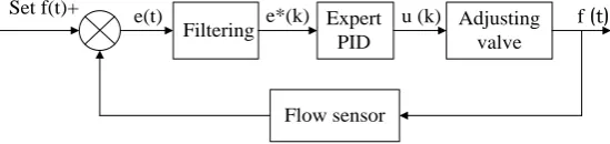
3.3. Flow Rate Interrupts Expert PID Control
For the flow rate control, there are several important influence functions, such as the impulse disturbance of the adjusting valve’s starting and stopping, control signals noise [19] [20] [21] and etc. Assuming the flow rate control error is e t
( )
and output is u k
( )
, the flow control system adopts expert PID control strategy,which the flow control chart is shown in Figure 9.
In Figure 9, the k-th error sampled-data filtering output is
( ) (
1) (
1)
( )
e∗ k = −α e∗ k− +αe∗ k (22)
where e∗
(
k−1)
is the (k-1)-th filtering output, α = −1 TeT d, T is sample time,d is constant time.
There are five cases for the expert decision processing of flow rate control:
Case 1: if e
( )
k f t1( )
∗ > , then the controller output is max (or min), the control system is equivalent to opened-loop control;
Case 2: if e∗
( )
k ∆e∗( )
k >0 and e∗( )
k < f2( )
t , the error is varying toab-solute value increase, then the controller is
( )
(
1)
p( ) (
1)
i( )
d( )
2(
1) (
2)
u k =u k− +k e k −e k− +k e k +k e k − e k− +e k− (23)
Case 3: if e∗
( )
k ∆e∗( )
k <0 and e k∗( )
∆e k∗(
− <1)
0 or e∗( )
k =0, the er-ror is varying to absolute value decrease or reaches equilibrium state, then the controller output is similar to the (23);Case 4: if e∗
( )
k ∆e∗( )
k <0 and e k∗( )
∆e k∗(
− >1)
0 and e( )
k f2( )
t∗ < ,
then the controller output is
( )
(
1)
p( )
u k =u k− +k e∗ k (24)
Case 5: if e∗
( )
k ≤ς, the error absolute value is to be enough small, then thecontroller adds integration part, reduces the stable error.
Adjusting valve Filtering
Set f(t)+ e(t) e*(k) Expert f (t)
PID u (k)
[image:11.595.235.510.651.716.2]Flow sensor
Remark 3.2: In Figure 9, the filter is first-order limited amplitude average principle, that is, after the e t
( )
sampled k times, removes the two biggestsam-pled-data, then obtains the average value for the rest of the k-2 sampled-data, to overcome the effect of signals impulse and peak disturbance, yields e∗
( )
k sentto expert PID controller, obtains the flow rate control signals in the interrupt routine organization block (OB34) at every 100 ms time and outputted from the 16th port of C_2 module with the pulse wave modulating form, control the ad-justing valve.
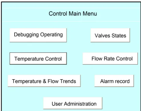
3.4. HMI Control Design
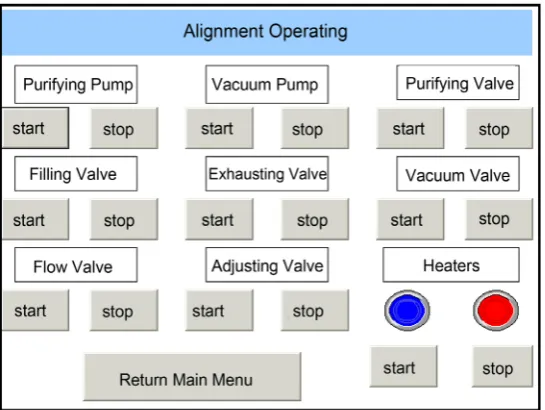
In this control system, applies the Siemens MP277 10# HMI as user operating interface, according to the user operating and requirements of production processing, the designed main operating interface is showed in Figure 10, which mainly includes the alignment operating control of valves, pumps and heaters as shown in Figure 11, the temperature and flow rate control user interface as shown in Figure 12, the temperature and flow rate trends interface.
4. Application and Control Analysis
In this section, the system control simulating and effective application are given and analyzed. The deposited wafers are assumed to be opaque.
Example 1. One type of poly-crystal silicon thin film which deposited on the glass substrate, its production need the SiH4 gas temperature maintained in
200˚C (Celsius degrees) and flow rate in 0.085 liters per second. The chamber temperature need be controlled error within 1˚C and the flow rate controlled within 5 seconds to achieve the set values of production. Some physical parame-ters of the diffusing chamber and SiH4 gas are given in Table 1.
Set Q = 2.5, R = 1.0,
γ
=1.0, α =0.5, τ =50 ms and the chamber external temperature T0=25 C , using Matlab control toolbox [18] to solve (21), obtains
[image:12.595.248.495.520.714.2]the output power u(t) is 0.2903 kw·˚C.
Figure 11. HMI alignment operating.
Figure 12. HMI temperature and flow control.
The temperature and flow rate control simulating performances which com-pared with traditional control methods [22] [23] [24] are shown in Figure 13 and Figure 14, respectively.
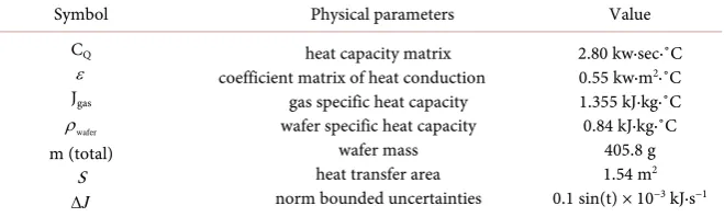
Example 2. The other kind of poly-crystal silicon thin film production need the temperature in 630˚C and flow rate in 0.15 liters per second, the chamber temperature should be controlled error within 2˚C and the flow rate controlled within 5 seconds, deposited on the Si substrate. Some physical parameters of the chamber and SiCl4 gas are given in Table 2.
when Q = 25 and R = 10,
γ
=0.95, α =0.5, τ =50 ms and chamber ex-ternal T0=20 C , obtains the output power u(t) is 0.3425 kw·˚C. The designed
[image:13.595.237.511.307.524.2]Table 1. Physical parameters in case 1.
Symbol Physical parameters Value
CQ ε Jgas
wafer
ρ
m (total) S
J
∆
heat capacity matrix coefficient matrix of heat conduction
gas specific heat capacity wafer specific heat capacity
wafer mass heat transfer area norm bounded uncertainties
2.80 kw·sec·˚C 0.55 kw·m2·˚C 1.355 kJ·kg·˚C 0.84 kJ·kg·˚C
[image:14.595.205.530.220.540.2]405.8 g 1.54 m2 0.1 sin(t) × 10−3 kJ·s−1
Table 2. Physical parameters in case 2.
Symbol Physical parameters Value
CQ ε Jgas
wafer
ρ
m (total) S
J
∆
heat capacity matrix coefficient matrix of heat conduction
gas specific heat capacity wafer specific heat capacity
wafer mass heat transfer area norm bounded uncertainties
2.80 kw·sec·˚C 0.55 kw·m2·˚C 0.526 kJ·kg·˚C 0.70 kJ·kg·˚C
410.5 g 1.54 m2 0.11 sin(t) × 10−3 kJ·s−1
Figure 13. Temperature control trajectory.
In Figure 15 and Figure 16, the designed control system simulating results show the flow control quickly, achieve control object thereabouts 5 seconds, due to the inertial effect of temperature which regulates 12 heaters power output reaching 630˚C at least 8 seconds, and temperature error within 1˚C (a group of actual control parameters are shown in Figure 12). The actual temperature and flow trends are shown in Figure 17 at different time scale (temperature and flow trends output from the left and right axis respectively, where temperature trend indicates the average values of the 12 zones temperature).
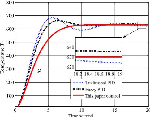
In this case, we check the control capability of the proposed controller when the chamber temperature varies from 630˚C to 800˚C at 20 seconds scale in the production. The temperature control trajectory is shown as Figure 18.
5 10 15 20 25
50 100 150 200 250 300
Time second
T
em
p
er
at
u
re T
/
℃
Figure 14. Flow rate control trajectory.
Figure 15. The trajectory of temperature.
Figure 16. The trajectory of flow.
0 5 10 15 20 25
0 0.02 0.04 0.06 0.08 0.1 0.12
Time second
F
lo
w
L
ite
rs
/ s
ec
o
n
d
Expert PID Fuzzy PID Traditional PID
0 5 10 15 20
100 200 300 400 500 600 700 800
Time second
T
em
p
er
at
u
re T
/
℃ 62018.2 18.4 18.6 18.8 19 630
640
Traditional PID Fuzzy PID This paper control
0 5 10 15 20 25 30
0 0.05 0.1 0.15 0.2
Time second
F
lo
w
L
ite
rs
/ s
ec
o
n
d
[image:15.595.252.498.515.715.2]Figure 17. The temperature and flow trends in the HMI.
Figure 18. The control trajectory of varying temperature.
Furthermore, in example 2, considering the system physical parameters per-turbed by 10%, and the temperature varies from 630˚C to 1100˚C at 15 seconds scale, then decreases to 660˚C at 30 seconds scale in the production, we apply the H∞ control scheme and expert PID to the perturbed system. Figure 19 shows the result of the variable temperature trajectory.
From the Figure 19, we can know that the temperature variable rates are about 80˚C·s−1 and 70˚C·s−1 from 20˚C ramp up to 630˚C and 1100˚C,
respec-tively, then decreasing rate is about 50˚C·s−1 from 1100˚C to 800˚C. Based
hard-ware configuring, compared with last results, our method is therefore able to cope with system perturbations, errors and uncertainties adequately, overcomes the shortcomings of the traditional methods, reduces the system control oscilla-tion and overshoot, improves the robustness of system and economizes power when applied to the actual system
5. Conclusion
[image:16.595.251.494.274.462.2]Figure 19. The temperature trajectory of parameter perturbed.
designed for poly-crystal silicon thin film production, and we apply Siemens PLC modules to build the mainly control hardware system. For diffusing cham-ber temperature, this paper designed expert PID controller to adjust the diffu-sion flow rate and H∞ control strategy to control 12 zones heaters power, to achieve rapid variable temperature. The user can easily and conveniently operate the production control by designed HMI. Lastly, the designed control system are simulated and applied in the actual production, and results show that the system control satisfies the requirements of production techniques and indicators for poly crystalline silicon thin film.
Acknowledgements
This work is supported by the Jiangsu Overseas Research & Training Program for University Prominent Young & Middle aged Teachers & President (2012- 2015).
References
[1] Nulman, J., Krusius, J.P. and Gat, A. (1985) Rapid Thermal Processing of Thingate Dielectrics: Oxidation of Silicon. IEEE Electron Device Letters, 6, 205-207. https://doi.org/10.1109/EDL.1985.26099
[2] Deaton, R. and Massoud, H.Z. (1992) Manufacturability of Rapid-Thermal Oxida-tion of Silicon: Oxide Thickness, Oxide Thickness VariaOxida-tion, and System Depen-dency. IEEE Transactions on Semiconductor Manufacturing, 5, 347-358.
https://doi.org/10.1109/66.175367
[3] Dilhac, J.M., Ganibal, C., Bordeneuve, J. and Nolhier, N. (1992) Temperature Con-trol in a Rapid Thermal Processor. IEEE Transactions on Electron Devices, 39, 201- 203. https://doi.org/10.1109/16.108231
[4] Norman, S.A. (1991) Optimization of Wafer Temperature Uniformity in Rapid Thermal Processing Systems. Tech. Rep., Dept. of Electrical Engineering, Stanford University.
on Semiconductor Manufacturing, 5, 180-188. https://doi.org/10.1109/66.149811 [6] Perkins, R.H., Riley, T.J. and Gyurcsik, R.S. (1995) Thermal Uniformity and Stress
Minimization during Rapid Thermal Processes. IEEE Transactions on Semicon-ductor Manufacturing, 8, 272-279. https://doi.org/10.1109/66.401001
[7] Yoshitani, N. and Hasegawa, A. (1998) Model-Based Control of Strip Temperature for the Heating Furnace in Continuous Annealing. IEEE Transactions on Control Systems Technology, 6, 146-156. https://doi.org/10.1109/87.664182
[8] Gyurcsik, R.S., Riley, T.J. and Sorrell, F.Y. (1991) A Model for Rapid Thermal Processing: Achieving Uniformity through Lamp Control. IEEE Transactions on Semiconductor Manufacturing, 4, 9-13. https://doi.org/10.1109/66.75858
[9] Lai, J.H. and Lin, C.T. (1999) Application of Neural Fuzzy Network to Pyrometer Correction and Temperature Control in Rapid Thermal Processing. IEEE Trans. on Fuzzy Systems, 7, 160-175. https://doi.org/10.1109/91.755398
[10] Choi, J.Y. and Do, H.M. (2002) A Learning Approach of Wafer Temperature Con-trol in a Rapid Thermal Processing System. IEEE Transactions on Semiconductor Manufacturing, 14, 1-10. https://doi.org/10.1109/TSM.2002.807740
[11] Yang, D.R., Lee, K.S., Ahn, H.J. and Lee, J.H. (2003) Experimental Application of a Quadratic Optimal Iterative Learning Control Method for Control of Wafer Tem-perature Uniformity in Rapid Thermal Processing. IEEE Transactions on Semi-conductor Manufacturing, 16, 36-44.https://doi.org/10.1109/TSM.2002.807740 [12] Li, X.F., Li, D.H., Gao, J.M. and Pang, M. (2013) Temperature Drift Compensation
Algorithm Based on BP and GA in Quartz Flexible Accelerometer. Applied Me-chanics and Mechanical Engineering, 249, 95-99.
https://doi.org/10.1007/s11633-015-0899-5
[13] Zhang, R.D., Xue, A.K. and Gao, F.R. (2014) Temperature Control of Industrial Coke Furnace Using Novel State Space Model Predictive Control. IEEE Transac-tions Industrial Informatics, 10, 2084-2092.
https://doi.org/10.1109/TII.2014.2350452
[14] Qiao, J.H. and Chai, T.Y. (2015) Intelligence-Based Temperature Switching Control for Cement Raw Meal Calcination Process. IEEE Transactions on Control Systems Technology, 23, 644-661.
[15] Shen, L., He, J.J., Yang, C.H., Gui, W.H. and Xu, H.L. (2016) Temperature Unifor-mity Control of Large-Scale Vertical Quench Furnaces for Aluminum Alloy Ther-mal Treatment. IEEE Transactions on Control Systems Technology, 24, 24-38. [16] Siemens, A.G. (2008) SIMATIC S7-300 Programmable Controller System Manual.
Beihang University Press, Beijing.
[17] Mahmoud, M.S. and Xia, Y.Q. (2012) Applied Control Systems Design. Springer- Verlag, London.https://doi.org/10.1007/978-1-4471-2879-3
[18] Boyd, S.P., Ghaoui, E., Feron, E. and Balakrishnan, V. (1994) Linear Matrix Inequa-lities in System and Control Theory. SIAM, Philadelphia.
https://doi.org/10.1137/1.9781611970777
[19] Ng, K.W. (1994) Control Valve Noise. ISA Transactions, 33, 275-286.
https://doi.org/10.1016/0019-0578(94)90098-1
[20] Lipták, B.G. (1995) Instrument Engineers Handbook: Process Control. Vol. 2, 3rd Edition, Butterworth-Heinemann, Oxford.
[21] Hu, H.-P. (2015) Influences of Interfacial Shear in Turbulent Film Boiling on a Ho-rizontal Tube with External Flowing Liquid. Engineering, 7, 754-764.
Controller for Integrated Control of Protected Cultivation. Emerald Group Pub-lishing Limited, Bingley.
[23] Sung, S.W., et al. (2009) Process Identification and PID Control. John Wiley & Sons, Hoboken.https://doi.org/10.1002/9780470824122
[24] Antonio, V. (2006) Practical PID Control. Springer-Verlag, London.
Submit or recommend next manuscript to SCIRP and we will provide best service for you:
Accepting pre-submission inquiries through Email, Facebook, LinkedIn, Twitter, etc. A wide selection of journals (inclusive of 9 subjects, more than 200 journals)
Providing 24-hour high-quality service User-friendly online submission system Fair and swift peer-review system
Efficient typesetting and proofreading procedure
Display of the result of downloads and visits, as well as the number of cited articles Maximum dissemination of your research work
Submit your manuscript at: http://papersubmission.scirp.org/