doi:10.4236/jemaa.2010.29072 Published Online September 2010 (http://www.SciRP.org/journal/jemaa)
Analysis of the Focusing Characteristics of Double
Negative Binary Diffractive Lens
Zongxin Wang1, Lizhi You2
1State Key Lab of Millimeter Waves Southeast University, Nanjing, China; 2Radar and Avionics Institute of AVIC, Wuxi,
China
Email: [email protected]
Received May 29th, 2010; revised July 26th, 2010; accepted August 5th, 2010
ABSTRACT
For a compact millimeter wave imaging system it is very important to design every component into small size, for the components in a millimeter wave system are usually much larger than those in an optical imaging system due to rela-tively long wave lengths. In this paper, we suggest a kind of binary diffractive lens (BDL) designed using double nega-tive materials (DNG) as the objective lens for a millimeter wave imaging system. The DNG-BDL has not only the ad-vantage of low profile but also small f number, which will be benefit for constructing a compact millimeter wave imag-ing system. Several DNG-BDL are designed and analyzed usimag-ing the FDTD method. The numerical results of the focal plane field of the DNG-BDL are presented, which show that the DNG-BDL with small f number has relatively better focusing characteristic than that of a double positive BDL with same f number.
Keywords: Millimeter Wave Imaging, Binary Diffractive Lens, Double Negative Material
1. Introduction
Since Veselago’s theory [1] about a homogeneous iso-tropic electromagnetic material in which both permittiv-ity and permeabilpermittiv-ity have negative real values (μ < 0,ε <
0) over thirty year’s ago, the properties of the double negative materials (DNG) have raised a great deal of interest, many interesting phenomena and applications of the DNG have been found, such as Plano-concave DNG lens [2], negative angles of refraction [3,4], enhanced focusing [4,5], backward wave antennas [6], and electri-cally small antennas[7]. In this paper, DNG was used to design binary diffractive lens (BDL) [8,9], whose poten-tial application is the objective lens in a millimeter wave (MMW) imaging system. In MMW imaging, sizes of the components are usually much larger than those in an op-tical imaging system due to relatively long wave lengths, so reducing the component’s sizes is very important for designing a compact MMW imaging system. The BDL has advantages of light weight and low profile [10,11] than ordinary curve face lens, which will accordingly benefit for building up compact imaging system. Besides the aforementioned advantages of an traditional BDL made of double positive medium (DPS), the DNG-BDL
with small f number (FN) is expected to have better fo-cusing characteristics than a DPS one, which is well- founded for as we know that Plano-concave DNG lens show good small FN [2] characteristics, and the small FN characteristic of lens is also very important for con-structing a compact imaging system especially at MMW frequencies. So in this paper, we present the design for-mulas of the DNG-BDL; several DNG-BDL are designed at frequency of 94GHz and analyzed using FDTD method which is powerful for analyzing DNG problems [12,13]; the focal plane fields of the DNG-BDL are presented to show the focusing characteristics of the DNG-BDL with small f number.
2. Design of the DNG-BDL
-80 -60 -40 -20 0 20 40 60 0.0 0.2 0.4 0.6 0.8 1.0 N o rmaliz ed f ield int ens it y mm Main lobe Side lobe
Figure 1. Focal field distribution for a typical imaging lens incident by plane wave.
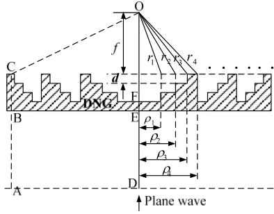
[image:2.595.353.539.314.403.2]netic waves passing through a lens, and the reason why energies concentrate into the main beam is that the phases of the electromagnetic waves reaching to the focal point have nearly same phases. So the basic rule for design a focusing lens is that every wave path to the focal point should be equal, for example the wave path ABCO in Figure 2 should equal to wave path DEFO.
Following the design rule just mentioned, take a 1/22
BDL (22 sub-zones in each zone) as an example [14], the
distance from the focal point to the lens are
2 1, 2,3
2 n
r f n n (1) where
rn is the distance from the focal point to the lens , n is the number index of the sub-zones, f is the focal length, λ is the wavelength. It is clear that there is λ/22 difference
(phase difference is π/2) between two neighboring rn. Waves propagated in DNG medium generate negative wave path differences compared to waves propagated in the air, which is opposite to that in DPS medium. Dif-
1 2 3 4 1
r r2r3r4
Figure 2. DNG-BDL.
ferent height of sub-zones will generate wave path dif-ference and this will compensate for the difdif-ference among all rn, then each wave path to the focal point will be equal. Accordingly, the sub-zone step height d is de-termined by the following equation
0 2
d
k d k d (2) where
kd is the wave number in the DNG medium and ac-cording to [12], kd r r when μr andεr are both negative, so from equation (2) we get
2 2
2 r rd d
,
i.e. 2 1
0, 0
2 r r 1 r r
d
(3)
For 1/2k BDL, there are 2k sub-zones in each zone, and the path difference between two neighboring sub- zones is λ/2k, then the parameters of this BDL are:
2
n k
r f n (4)
1 2 2
1
2 2
n nf k n k
(5)
1 2k r r 1
d
(6)
3. Numerical Results of the DNG-BDL
Among numerous methods for solving DNG problems, FDTD method [15] is a relatively convenient and pow-erful one, so FDTD method is used to analyze the DNG- BDL in this paper. There existing three types of fre-quency dispersive FDTD methods: the ecursive convolu-tion (RC) method [16], the auxiliary differential equaconvolu-tion (ADE) method [17] and the Z-transform method [18]. The ADE FDTD method is selected here and the Drude model [12,15] is used to model the DNG medium where permeability μ (ω) and permittivity ε (ω) take the fol-lowing forms:
2
0 1 2
p , 2
0 1 2
p
(7) where
ωp is the material’s resonant frequency.
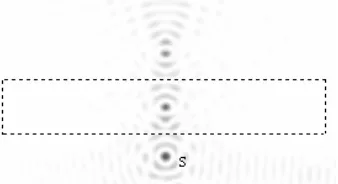
[image:2.595.74.271.551.705.2]electric field intensity obtained by our program at fre-quency 94 GHz after 2000 time steps is shown in Figure 3, where S denotes the point source; the focus occurring in and outside the slab agrees well with Pendry’s theory.
The BDL designed and analyzed here are axisymmet-ric, so a symmetry boundary (see Figure 4) is set in the computation model to save computation space; the total FDTD region is enclosed by the PML and divided into total-field and scattered-field, the plane wave source is generated by 1D-FDTD method [19] and introduced through the connection boundary of the total-field and scattered-field by a combined total–scattered field for-mulation [20]; the focal plane field (FPF) is then com-puted through Stratton-Chu integral of the field at the output-boundary.
The FPF (f = 30e-3) of a 1/2 DPS-BDL (εr = 2.2, con-tains five zones) was computed using the FDTD code and compared with that obtained by boundary element method (BEM) as shown in Figure 5, the two results agree well with each other.
[image:3.595.311.538.83.455.2]Then several DNG-BDL are designed and analyzed using the FDTD method. Shown in Figure 6(a) is the
[image:3.595.330.517.89.258.2]Figure 3. The electric field intensity over the DNG slab simulation space.
Figure 4. FDTD computation model.
-30 -20 -10 0 10 20 30
-1 0 1 2 3
|E
|
y /mm
FDTD BEM
Figure 5. FPF of a 1/2 DPS-BDL.
4 6 8
8 16 24 32 40 48
y / mm
x/m m
-40 -20 0 20 40
0.0 0.2 0.4 0.6 0.8 1.0
N
[image:3.595.90.259.358.450.2] [image:3.595.120.479.503.686.2]o
rmalized |
E
|
y / mm
DNG-BDL, r=r=-1
DPS-BDL, r=2.2
0 5 1 0
8 16 24 32 40 48
y/
mm
x/mm
(a) (b) (c)
Figure 6. Focal plane fields of the DNG-BDL(μr = –1, εr = –1) and DPS-BDL(εr = 2.2) with FN = 1. (a) DNG-BDL; (b) Focal
4 5 6 7 8 9 4
8 12 16 20 24
y/mm
x/mm
-20 -10 0 10 20
0.0 0.2 0.4 0.6 0.8 1.0
[image:4.595.122.475.86.260.2] [image:4.595.118.482.303.483.2] [image:4.595.137.463.527.688.2]Norma
lized |E|
y / mm
DNG-BDL, r=r
DPS-BDL, r
0 5
0 4 8 12 16 20 24
y/
m
m
x/mm
(a) (b) (c)
Figure 7. Focal plane fields of the DNG-BDL(μr = εr = –1) and DPS-BDL(εr = 2.2) with FN = 0.21. (a) DNG-BDL; (b) Focal
plane field; (c) DPS-BDL.
4 5 6 7 8
8 16 24 32 40 48
y/mm
x/mm
-60 -40 -20 0 20 40 60
0.0 0.2 0.4 0.6 0.8 1.0
N
o
rma
liz
ed |
E
|
y/mm
DNG-BDL, r=r=-2 DPS-BDL,
r=3.78
0 5
0 8 16 24 32 40 48
y /mm
x/m m
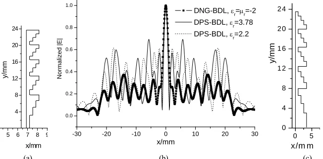
(a) (b) (c)
Figure 8. Focal plane fields of the DNG-BDL(μr = εr = –2) and DPS-BDL (εr = 3.78) with FN = 1. (a) DNG-BDL; (b) Focal
plane field; (c) DPS-BDL.
4 5 6 7 8 9 4 8 12 16 20 24
y/
mm
x/mm
-30 -20 -10 0 10 20 30
0.0 0.2 0.4 0.6 0.8 1.0
Normalized |E
|
x/mm
DNG-BDL, r=r=-2
DPS-BDL, r=3.78
DPS-BDL, r=2.2
0 5
0 4 8 1 2 1 6 2 0 2 4
y/
mm
x/m m
(a) (b) (c)
Figure 9. Focal plane fields of the DNG-BDL(μr = εr = –2) and DPS-BDL with FN = 0.21. (a) DNG-BDL; (b) Focal plane field ;
structure of a 1/22 DNG-BDL (μ
r = –1, εr = –1) with four zones, focal length f = 105 mm and diameter D = 105 mm (FN = 1). The FPF of the DNG-BDL was computed using the FDTD method and compared with that of a DPS-BDL (εr = 2.2), see Figure 6(b). The structure of the DPS-BDL with same number of zones, focal length and diameter as that of the DNG-BDL is given in Figure 6(c). It is clear from Figure 6 that the FPF side lobes of the DNG-BDL are lower than that of the DPS-BDL, as has been explained in section 2 that lower side lobes of the DNG-BDL will be benefit to the imaging qualities.
For BDL of small FN, the FPF side lobes of the DNG-BDL are relatively even much lower than that of the DPS-BDL, an example is shown in Figure 7 where the focal length of the 1/22 DNG and DPS BDL (five
zones) are f = 10 mm, diameter D = 47 mm (FN = 0.21). The FPF of two DNG-BDL with μr = εr = –2 and two DPS-BDL with εr = 3.78 were also computed. Shown in
Figure 8 are the results of the BDL with focal length f = 105 mm and diameter D = 105 mm (FN = 1); shown in Figure 9 are results of the small FN BDL with focal length f = 10 mm, diameter D = 47 mm (FN = 0.21). The results in Figure 8 and Figure 9 also support the conclu-sion that smaller FN DNG-BDL has relatively lower side lobes than that of DPS-BDL with same FN, and will get better imaging quality as a result.
4. Conclusions
The DNG-BDL which has good characteristics of low profile and small f number is studied in this paper. The design formulas of the DNG-BDL are presented and several DNG-BDL are designed and analyzed using the FDTD method. The focal plane fields of several DNG- BDL are given and compared with that of DPS-BDL; the compared results show that the DNG-BDL with small f
number has better focusing characteristics than that of DPS-BDL, and this property makes it very useful to be taken as the objective lens to construct a compact milli-meter wave imaging system.
REFERENCES
[1] V. G. Veselago, “The Electrodynamic of Substance with Simultaneously Negative Values of ε and μ,” Soviet Physics Uspekhi, Vol. 10, No. 4, 1968, pp. 509-514. [2] N. Engheta and R. W. Ziolkowski, “A Positive Future for
Double-Negative Metamaterials,” IEEE Transactions on Microwave Theory and Techniques, Vol. 53, No. 4, 2005, pp. 1535-1556.
[3] A. Shelby, D. R. Smith and S. Schultz, “Experimental Verification of a Negative Index of Refraction,” Science, Vol. 292, No. 5514, 2001, pp. 77-79.
[4] J. B. Pendry, “Negative Refraction Makes a Perfect
Lens,” Physics Review Letters, Vol. 85, No. 18, 2000, pp. 3966-3969.
[5] G. G. V. Eleftheriades, A. K. Iyer and P. C. Kremer, “Planar Negative Refractive Index Media Using Periodi-cally L–C Loaded Transmission Lines,” IEEE Transac-tions on Microwave Theory and Techniques, Vol. 50, No. 12, 2002, pp. 2702-2712.
[6] A. A. Grbic and G. V. Eleftheriades, “Experimental Veri-fication of Backward-Wave Radiation from a Negative Refractive Index Metamaterial,” Journal of Applied Phy-sics, Vol. 92, No. 10, 2002, pp. 5930-5935.
[7] R. W. Ziolkowski and A. Kipple, “Application of Double Negative Metamaterials to Increase the Power Radiated by Lectrically Small Antennas,” IEEE Transactions on Antennas and Propagation, Vol. 51, No. 10, 2003, pp. 2626-2640.
[8] M. Skeren, I. Richter and P. Fiala, “Design of Binary Phase-Only Diffractive Optical Elements for Laser Beam Shaping,” Proceedings of SPIE, Vol. 4095, 2000, pp. 154-164.
[9] S. N. Toma, A. Alexandrescu, D. Apostol, V. Nascov and D. Cojoc, “Gaussian to Rectangular Laser Beam Shaping Using Diffractive Optical Elements,” Proceedings of SPIE, Vol. 5972, 2005, pp. G1-G8.
[10] D. N. Black and J. C. Wiltse, “Millimeter-Wave Charac-teristics of Phase-Correcting Fresnel Zone Plates,” IEEE Transactions on Microwave Theory and Techniques, Vol. 35, No. 12, 1987, pp. 1122-1129.
[11] S. M. Stout-Grandy, A. Petosa, I. V. Minin, O. V. Minin, and J. Wight, “A Systematic Study of Varying Reference Phase in the Design of Circular Fresnel Zone Plate An-tennas,” IEEE Transactions on Antennas and Propaga-tion, Vol. 54, No. 12, 2006, pp. 3629-3637.
[12] R. W. Ziolkowski and E. Heyman, “Wave Propagation in Media Having Negative Permittivity and Permeability,” Physical Review E, Vol. 64, No. 5, 2001, pp. 1-15. [13] M. Y. Wang, D. B. Ge, J. Xu and J. Wu, “FDTD Study
on Back Scattering of Conducting Sphere Coated with Double-Negatibe Metamaterials,” International Journal of Infrared and Millimeter Waves, Vol. 28, No. 2, 2007, pp. 199-206.
[14] Z. X. Wang and W. B. Dou, “Design and Analysis of Several Kinds of Dielectric Lens Antennas,” Journal of Electromagnetic waves and Applications, Vol. 20, No. 12, 2006, pp.1643-1653.
[15] Y. Zhao, P. Belov and Y. Hao, “Accurate Modelling of Left-Handed Metamaterials Using an FDTD Method with Spatial Averaging at the Boundaries,” Journal of Optics A: Pure and Applied Optics, Vol. 9, 2007, pp. S468-S475. [16] R. Luebbers, F. P. Hunsberger, K. Kunz, R. Standler and
M. Schneider, “A Frequency-Dependent Finite-Differen ce Time-Domain Formulation for Dispersive Materials,” IEEE Transactions on Electromagnetic Compatability, Vol. 32, No. 3, 1990, pp. 222-227.
Microwave Theory and Techniques, Vol. 41, No. 4, 1993, pp. 658-664.
[18] D. M. Sullivan, “Frequency-Dependent FDTD Meth-ods Using Z Transforms,” IEEE Transactions on An-tennas and Propagation, Vol. 40, No. 10, 1992, pp. 1223-1230.
[19] W. P. Dennis and S. Y. Shi, “Formulation and Applica-tion of the Finite-Difference Time-Domain Method for
the Analysis of Axially Symmetric Diffractive Optical Elements,” Journal of Optical Society America A, Vol. 16, No. 5, 1999, pp. 1131-1142.