ISSN Online: 1947-394X ISSN Print: 1947-3931
DOI: 10.4236/eng.2019.116025 Jun. 28, 2019 332 Engineering
Analysis of Pull-Out Behaviour
of Straight and Hooked
End Steel Fibres
Sadoon Abdallah, David W. A. Rees
College of Engineering, Design and Physical Sciences, Brunel University London Uxbridge, London, UK
Abstract
The effective utilisation of steel fibre reinforced concrete (SFRC) requires in-depth and detailed understanding of bonding mechanisms governing the tensile behaviour. In response to this demand, this study presents an em-pirical description of the axial force required to pull out a hooked end steel fibre from a cementitious matrix. It is based upon consistent experimental tests that show the force versus displacement plot is formed from a se-quence of events in which partial and full debonding at the interface is fol-lowed by bending of the hook knee to raise the force to its maximum. A loss of peak force occurs with the reversed plasticity involved in a full straigh-tening of the fibre that precedes the rapid sliding to its full removal under a falling force. The stages are assembled in the said order with a piecewise connection between linear segments and a curve of exponential decay. A power law can be introduced to describe the knee bending stage if pre-ferred. The normalised co-ordinates were adopted for the simple mathe-matical discontinuous function of the full pull-out process. Normalising force and displacement for hooked fibre is based upon the maximum values found for straight fibre pull out. This would apply to an overall embedded length of unity and a unit peak force for a full debonding of straight fibre in similar materials. For hooked fibre the normalised co-ordinates given refer to the initiation and duration of each event to be tabulated at fractions of the embedded length with multiples of that force. Such predictions are seen to be in good agreement with average pull-out response curves.
Keywords
Pull-Out Behaviour, Plastic Hinge, Mechanical Anchorage, Hooked End Fibre, Analytical Formulation
How to cite this paper: Abdallah, S. and Rees, D.W.A. (2019) Analysis of Pull-Out Behaviour of Straight and Hooked End Steel Fibres. Engineering, 11, 332-341. https://doi.org/10.4236/eng.2019.116025
Received: March 26, 2019 Accepted: June 25, 2019 Published: June 28, 2019
Copyright © 2019 by author(s) and Scientific Research Publishing Inc. This work is licensed under the Creative Commons Attribution International License (CC BY 4.0).
DOI: 10.4236/eng.2019.116025 333 Engineering
1. Introduction
DOI: 10.4236/eng.2019.116025 334 Engineering
2. Experimental Study
2.1. Samples Preparation and Test Setup
The pull-out tests on single steel fibre were performed using the cube of (100 × 100 × 100 mm). In each specimen, one steel fibre was placed carefully in a hole made through the bottom of moulds. The embedded length (LE) was one half of
the fibre length (i.e. 30 mm). For compressive strength test three cubes of (100 × 100 × 100 mm) were prepared for each mixture. The mixtures were prepared using a laboratory Pan mixer. During specimen fabrication, the components were firstly dry mixed for approximately 1 min followed by the addition of water and superplasticizer to the dry mixture. The mixture was then mixed for 11 min. After casting and vibration, the specimens were covered with a thin polyethylene film and left for 24 h at room temperature. Then specimens were removed from their moulds and cured for a further 28 days in the conditioning chamber (20˚C ± 2˚C, 96% ± 4% RH). For both compressive and pull-out specimens, the test was carried out at an age of 30 ± 2 days and the average value of six specimens was adopted.
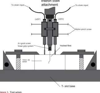
[image:3.595.212.536.420.723.2]The pull-out tests were performed using a specially designed grip system, as illustrated in Figure 1, which was attached to an Instron 5584 universal testing machine. The grips were designed such that the forces applied to the fibre pro-vided a true reflection of the real situation experienced by fibres bridging a crack. The body of the gripping system was machined in a lathe using mild steel
DOI: 10.4236/eng.2019.116025 335 Engineering
and had a tapered end to allow the insertion of four M4 grub screws (Figure 1). These were then tightened around the steel fibre to an equal torque for an even distribution of gripping pressure to minimise the deformation of the fibre ends and avoid breakage at the tip. Two linear variable differential transformer (LVDT) transducers were used to measure the distance travelled by the steel fibre relative to the concrete face during testing (i.e. the pull-out distance). They were held in place using aluminium sleeves on either side of the main grip body (Figure 1). The LVDT’s had ball bearings at the tips to allow for accurate readings on the face of the samples. The sample was secured to the Instron base using clamps with riser blocks and M16 studs. The specimen was positioned on a brass round disc to remove any discrepancies in the sample base and allow for distortion. In all pull-out tests, a displacement rate of 10 mm/s was adopted.
2.2. Pull-Out Mechanisms of Straight Fibres
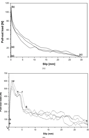
It can be seen from Figure 2(A) that the pull-out behaviour of straight fibre in-volves a combination of two different mechanisms: de-bonding (stages (o-a) and (a-b)) and frictional pull-out (stage (b-c)). Here, the de-bonding arising from cracking within and along the interfacial transition zone (ITZ) is followed by fi-bre pull-out under frictional resistance only. Figure 3(A) shows the average pull-out-slip curve of straight fibre embedded in a concrete matrix up to half fi-bre length i.e. 30 mm. The mix proportions, specimen’s preparation and testing method are given in [6].
The pull-out-slip response of straight fibres is characterized by a rapid in-crease in pull-out load (a-b) followed an equally rapid drop at (b), indicating that the fibre de-bonds suddenly from the concrete (Figure 2(A)). Thereafter, the pull-out load from (b-c) continues to fall with increasing slip. Hence, the straight fibres bond is made up only of chemical adhesion and static friction with no mechanical interlock. So, once these mechanisms are overcome, the fi-bre slips with a diminishing pull-out force necessary to overcome kinetic friction in the remaining contact zone (Figure 3(A)).
2.3. Pull-Out Mechanisms of Hooked End Fibres
Initial mechanisms (stages: o-a, a-b and b-c) governing the pull-out behaviour of hooked end fibres are similar to those measured for straight fibres (i.e.
DOI: 10.4236/eng.2019.116025 336 Engineering (A)
[image:5.595.259.487.69.694.2](B)
DOI: 10.4236/eng.2019.116025 337 Engineering (A)
[image:6.595.218.532.66.552.2](B)
Figure 3. Pull-out load-slip curves: (A) Straight fibre and (B) Hooked end fibre.
When PH1 has straightened, the wire moves into the straight part of the chan-nel. Then moving and straightening of PH2 results in a slight decrease in pull-out load (stage d-e). Once both PH1 and PH2 are completely deformed and straightened, the pull-out load need only overcome kinetic frictional resistance as for a straight fibre (stage g-h). This phase prevails until the whole fibre is completely removed from the matrix.
3. Empirical Formulation
DOI: 10.4236/eng.2019.116025 338 Engineering
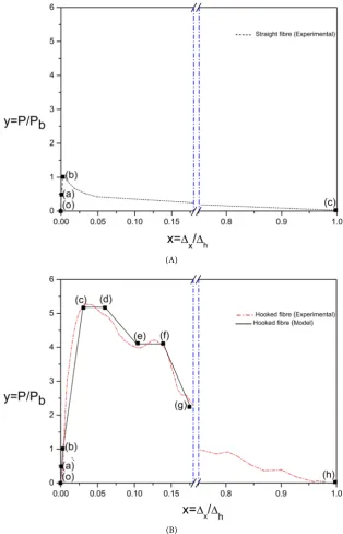
bend fibres is shown in Figure 4(A) and Figure 4(B), respectively. Experiment [7]
suggests that the normalised co-ordinates permit any fibre/cementitious material combination. They refer to the maximum force (Pb) at (b) in a straight fibre of unit embedded length at (h) [8]. In Figure 4, P represents the pull-out force and Δ is displacement in which the corresponding ratios P/Pb and Δx/Δh are relative
to straight fibre pull out.
The pull-out stage equations adopted for a hooked end, high tensile steel fibre and high strength concrete are given in Table 1 in which x and y are the norma-lised displacement and pull-out force, respectively.
(A)
[image:7.595.215.530.215.704.2](B)
DOI: 10.4236/eng.2019.116025 339 Engineering Table 1. Main stages of pull-out process of hooked-end fibre.
Stage Description Equation
o-a When a pull-out load y≤ya, the fibre remain perfectly bonded to the matrix and the
interface is kept in an elastic bond condition. y=mx m, =ya xa (0≤ ≤x xa)
a-b When y>ya, a part of the fibre is still fully bonded to the matrix while the remaining part is de-bonded.
1
, a , 1
b
b a
y
y mx c m c mx
x x
−
= + = = −
−
(xa≤ ≤x xb)
b-c Once interface de-bonding is completed at (b), the horizontal portion of the fibre must overcome kinetic friction as the hooked end of the fibre undergoes reverse bending.
2
2
1 1
, , 1
1 c
b c b
y y
y mx c m c x
x x x
− −
= + = = −
− −
(xb≤ ≤x xc)
c-d Due to the cold work from both plastic hinges (PH1 and PH2), the pull-out load remains until the fibre pulled by an additional distance ( ) d c
x −x . y=yc=yd (xc≤ ≤x xd)
d-e When PH1 has straightened, the fibre moves into the straight part of the channel. Then moving and straightening of PH2 results in a slight decrease in pull-out load. , ,
d e
d d
d e
y y
y mx c m c y mx
x x
−
= + = = −
−
(xd≤ ≤x xe)
e-f At this stage, the load remains until the fibre is pulled by an additional distance
(
xf−xe)
. y=ye=yf(
xe≤ ≤x xf)
f-g Once both PH1 and PH2 are completely deformed and straightened, the load drops to (g) with no plastic hinges active. , ,
f g
f f
f g
y y
y mx c m c y mx
x x
−
= + = = −
−
(
xf≤ ≤x xg)
g-h At this stage, the pull-out load need only overcome kinetic frictional resistance as for a straight fibre. This phase prevails until the whole fibre is completely removed from the matrix at (h).
( 1) 1 xg
g
y=y −e −
(
xg≤ ≤x xh)
Note 1: For stage (a-b): A straight fibre pull-out load Pb is derived from the normalised ordinate yb for two straight intersecting lines that lie within ranges (o-a) and (a-b) as shown in Figure 3. That is, from Figure 3:
(
) (
)
b oa a ab b a oa ab a ab b
y =m x +m x −x = m −m x +m x
Note 2: For stage (b-c): Should a power law curve be preferred this is written as:
n b b y x y x =
where debonding co-ordinate (xb, 1) appear from Note 1 above and n≤1 is a
reversed bending index suited to the material combination as shown in Figure 4.
Note 3: The plateau load attained for region (b-c) is provided by the virtual
work principle [8]. This principle refers the two hinges plastic bending to the collapse loading at (c-d) given in normalised co-ordinates as the difference:
c b
y −y
Note 4: Similar to Note 3 the plateau load for given of refers to single hinge
DOI: 10.4236/eng.2019.116025 340 Engineering
4. Conclusion
A schematic pull-out plot identifies with linear segments within each stage of fi-bre resistance. Bond fi-breakdown occurs in two stages with an embedded straight fibre attaining a maximum force at full debonding. There follows an exponential decay as the fibre to retracted with diminishing resistance [9]. Hooked fibre promotes an intermediate deformation stage. Here the anchorage provided by a double bend hook raises the force to a greater level necessary for it to be with-drawn. During straightening of the hook’s opposing bends the pull out force versus deflection plot appears as a plateau under the greatest force attained. Normalised co-ordinates used with a hooked fibre correspond to a unit embed-ded length of fibre and a relative force ratio to straight fibre to enable their con-version to the force and displacement measured in a test. Tabulated co-ordinates given for each stage of fibre resistance show a maximum force ratio of five with pull-out less than 10% of fibre length. Thereafter the greater part of the norma-lised plot is consumed in retracting a straightened fibre under a diminishing re-sistance which commences consistently at a force ratio of unity. The empirical discontinuous function for the whole of pull-out associates regions conveniently between intersections of linear segments. These connect with an exponential for decay in a single constant. The simplification adopted affords a library of co-ordinates for practical applications in various material combinations.
Acknowledgements
The first author is grateful for the financial support provided by the Ministry of Higher Education and Scientific Research of the Iraqi Government.
Conflicts of Interest
The authors declare that no conflicts of interest have arisen from the publication of any of the material presented in this paper.
References
[1] Panda, B., Chandra Paul, S. and Jen Tan, M. (2017) Anisotropic Mechanical Per-formance of 3D Printed Fiber Reinforced Sustainable Construction Material. Mate-rials Letters, 209, 146-149. https://doi.org/10.1016/j.matlet.2017.07.123
[2] Yan, L., Xing, Y., Zhang, J. and Li, J. (2013) High-Temperature Mechanical Proper-ties and Microscopic Analysis of Nano-Silica Steel Fibre RC. Magazine of Concrete Research, 65, 1472-1479. https://doi.org/10.1680/macr.13.00143
[3] Tadepalli, P.R., Mo, Y. and Hsu, T.T. (2013) Mechanical Properties of Steel Fibre Concrete. Magazine of Concrete Research, 65, 462-474.
https://doi.org/10.1680/macr.12.00077
[4] Abdallah, S., Fan, M. and Cashell, K.A. (2017) Pull-Out Behaviour of Straight and Hooked-End Steel Fibres under Elevated Temperatures. Cement and Concrete Re-search, 95, 132-140. https://doi.org/10.1016/j.cemconres.2017.02.010
DOI: 10.4236/eng.2019.116025 341 Engineering [6] Abdallah, S. and Fan, M. (2017) Anchorage Mechanisms of Novel Geometrical
Hooked-End Steel Fibres. Materials and Structures, 50, 139.
https://doi.org/10.1617/s11527-016-0991-5
[7] Alwan, J.M., Naaman, A.E. and Guerrero, P. (1999) Effect of Mechanical Clamping on the Pull-Out Response of Hooked Steel Fibers Embedded in Cementitious Ma-trices. Concrete Science and Engineering, 1, 15-25.
[8] Naaman, A.E., Namur, G.G., Alwan, J.M. and Najm, H.S. (1991) Fiber Pullout and Bond Slip. I: Analytical Study. Journal of Structural Engineering, 117, 2769-2790.
https://doi.org/10.1061/(ASCE)0733-9445(1991)117:9(2769)
[9] Abdallah, S., Fan, M. and Rees, D.W. (2018) Bonding Mechanisms and Strength of Steel Fiber-Reinforced Cementitious Composites: Overview. Journal of Materials in Civil Engineering, 30, Article ID: 04018001.