Abstract—It refers to the use of a graphical technique in combination with the experimentation standardized by ASTM G99 to identify a parameter that characterizes and quantifies the wear behavior of a steel thermally and/or chemically variously treated, such as those used to build tools for working hard materials or moulds for the powder metallurgy. In particular, the experimental procedure adopted, the data acquisition modes of the tests, the processing mode and interpretation of these latter are described. Finally, the precision with which the wear parameter is evaluated by the graphical technique and the possibility to distinguish - with only one test - the wear behavior of the treated surface layer from that of the base metal are pointed out. The material used for the creation of the various specimens' samples is the sintered Vanadis 4 Extra. Each sample was subjected preliminarily to one or two of the following treatments: quenching, cryogenization, nitrogenization and coating with the PVD coating technique.
Index Terms — Wear, Pin on Disk, Experimental Analysis of the Images, Sintered Steels, Surface Treatments, Moulds, Powder metallurgy, Tools.
I. INTRODUCTION
HE moulds used in powder metallurgy are normally subjected to high trial conditions during the pressing of the powders, both for the high values of the loads required to obtain pressed density comparable to those of similar material obtained by fusion, and for the geometries, sometimes scarce, locally or globally, to obtain complex or extremely moderate geometrical particulars, and, again, for the need to maintain machining tolerances between the components of the mould almost unchanged over the time, to ensure a high production with dimensional tolerances of the product contained within acceptable limits. Several materials have mechanical features suitable for this use, but they are not always able to meet the needs of the sector, which for economic reasons require higher and higher performance of materials, in terms of resistance to breaking and wear. The states of stress to which they are
Manuscript received March 23, 2015; revised March 23, 2015. M. Grasso is with the Department of Industrial Engineering, University of Naples Federico II, P.le V. Tecchio 80 - 80125 Naples, Italy (e-mail: marzio.grasso @unina.it).
F. Penta is with the Department of Industrial Engineering, University of Naples Federico II, P.le V. Tecchio 80 - 80125 Naples, Italy (e-mail: [email protected]).
G.P. Pucillo is with the Department of Industrial Engineering, University of Naples Federico II, P.le V. Tecchio 80 - 80125 Naples, Italy (corresponding author, phone: +390817682378; e-mail: [email protected]). V. Rosiello is with the Department of Industrial Engineering, University of Naples Federico II, P.le V. Tecchio 80 - 80125 Naples, Italy (e-mail: [email protected]).
subjected in operation, essentially derive from the repeated loads, from rubbing the surfaces of the punches against those conjugated of the matrix and from the thermal conditions that develop locally, when they are not imposed globally to improve the product.
Consequently, the material must have a high static resistance (to traction and compression), remarkable fracture toughness, an excellent fatigue behavior and a hardness that can confer a high resistance to wear. There are numerous researches [1 ÷ 9] aimed at identifying new production processes or new manufacturing technologies or, again, new treatments of known materials which confer to the material the performance features desired. The results, however, confirm what was already known, namely, that the above properties cannot be raised all in equal measure, as, in general, when one increases the others decrease. However, it is important to know if and how a feature can be improved at the expense of another that in a specific application can be partially sacrificed in order to optimize its use. For this reason, in collaboration with a machining Company, an extensive campaign of tests for the optimization of the mechanical properties of materials for tools and for moulds was conducted, within which we had to face, among other things, the longstanding problem of the wear characterization of an only superficially hardened material with a nitrogenization or PVD coating. This work describes the operational procedures, not all standardized, followed to solve this problem. In particular, we propose a procedure to quantify the wear parameter to be assigned to the treated material, although this is confined in a layer of micrometer thickness. The analysis of the results achieved seems very positive and, in any case, provides sufficient elements to evaluate the validity and reliability of the procedure.
II. MATERIAL AND RELATED TREATMENTS
A bibliographic analysis on materials used by metallurgical companies [4 ÷ 9] and from the campaign of tests conducted for the optimization of the mechanical properties of materials for tools and moulds [1] shows that the Vanadis 4 Extra, a chromium-vanadium-molybdenum highly alloyed steel with the addition of other alloying elements (s. Table 1), has mechanical characteristics that make it particularly attractive for applications requiring high performances, such as, in fact, the construction of moulds used in the sintering processes. A further property is the remarkable dimensional stability gained in the treatments of quenching and hardening, together with a high fracture toughness and a considerable hardness that can be obtained
Wear Characterization of a Coated Sintered
Steel for Moulds
M. Grasso, F. Penta, G.P. Pucillo, V. Rosiello
with coatings or with special surface treatments.
TABLEI
CHEMICAL PROPERTIES OF VANADIS 4EXTRA
C Cr Mn Mo Si V Fe
1.4 % 4.7 % 0.4 % 3.5 % 0.4 % 3.7 % 85.9%
According to its technical specifications, Vanadis results having a good adhesive, abrasive or mixed type wear resistance.
The treatments chosen for the construction of the specimens for the wear tests are briefly described below.
- Austenization T1 - T2, quenching and tempering
The material is brought to a temperature of pre-heating equal to 450-500 °C, and then reaches the austenization temperature, T1 or T2, which may vary between 1050 °C and 1180 °C, depending on the desired final hardness. In the case of Vanadis 4 Extra a temperature T1 (T2) has been adopted, equal to 1060 °C (1150 °C), with n. 3 consecutive temperings, at 560 °C, which ensured a surface hardness of 59 ± 1 HRC (62 ± 1 HRC).
- Cryogenic
For alloyed steels, as a result of the treatments of quenching, not all of the austenite is transformed into martensite; at room temperature it retains a content varying between 5% and 20%. After the second tempering, a subsequent cooling at temperatures below 0 °C (-80 ÷ -70 °C) allows to achieve the almost total transformation of the retained austenite. The end result, in general, is an increase in both the hardness and the fracture toughness.
- Gas nitrogenization
This process allows the introduction of nitrogen in the surface layers of the steel, resulting in a strong hardening and an increase in wear resistance [14]. Starting from the use of ammonia vapor, the thermal dissociation of its molecule catalyzed by the steel is exploited, which produces the following reaction:
2NH3 → 2N + 3H2.
The hardness and the depth of the layer are essentially linked to the steel composition, the degree of dissociation of the ammonia, the treatment temperature (about 500 °C) and the residential time. The thickness of material effectively treated does not exceed 2 or 3 tenths of a millimeter.
- PVD coating
It consists in depositing solid particles of hard substances, such as TiN, TiCN, AlTiN, ZrN, CrN, on the surface of the material in question. The process is done by placing the affected component in an appropriate room, in which the vacuum is created, with the material with which it will be covered [16]. The latter is heated by means of thermal radiated energy, in order to form a gaseous mixture of solid particles in the same room. Applying, then, a predetermined potential difference between the material to be coated and the coating, so that these constitute the electrodes of a circuit, it is possible to realize the above-mentioned coating. The technique allows to form extremely hard surface deposits on the object surface, at a depth variable from a minimum of 0.1 μm to a maximum of 10 μm.
III. EXPERIMENTATION
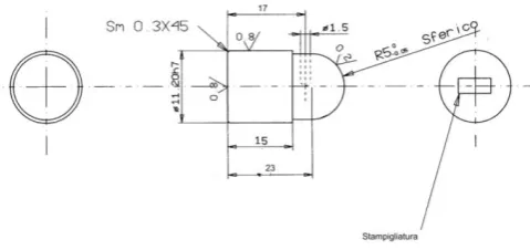
The experimental technique adopted for wear tests is the "Pin on disk", described in ASTM G99 Standard. It involves the use of a specimen, having a spherical extremity, to be placed on a disk with the axis of symmetry perpendicular to the plane of the disk. The samples that can be used generally have the shape of a bullet or a sphere; in our case the first one was chosen, whose dimensions are shown in Fig. 1.
Both roughness and diameter of the cap fall in the measures provided for by the norm, which requires a value of 0.8 μm and 2÷10 mm respectively. The specimen has a blind hole with a small diameter for measuring the temperature.
[image:2.595.308.548.253.366.2]The counter-disk is made up of a metal alloy that is harder than the samples to be tested.
Fig. 1. Specimen geometry.
To carry out the continuous rubbing of the specimen and to ensure the squareness of its axis compared with the disk's horizontal plane, the specimen was housed in a specimen-holder integral to a horizontal arm. This arm was secured to the disk-holder plane by means of a cylindrical hinge with a horizontal axis, in order to allow its rotation in the plan normal to the disk during the interruption of the test for acquiring the wear data.
[image:2.595.319.541.586.756.2]A hinge height adjustment system was built to ensure a correct horizontality of the arm, on which the verticality of the specimen axis depends. Moreover, a length-adjustable arm necessary for neutralizing the arm's weight (s. Fig. 2) was built to use always different sliding tracks when switching among specimens.
The disk is rotated by a 1.8 kW three-phase asynchronous engine with inverter. An optical rev counter was used to monitor the actual value of the space driven by the specimen on the disk.
An image scanning system rather than the traditional techniques (based on the measurement of the imprint diameter, or of the reduction of the specimen height or weight) was used due to its ease of use and, above all, to the higher precision it can give.
Such technique together with the possibility to rotate the specimen-holder arm allowed a fast image scanning, with a post-processing step almost in real time, and a repositioning of the specimen on the disk in correspondence with the imprint generated by the specimen itself in the step previous to scanning.
This made it possible to proceed with the test, by carrying out numerous scans and without modifying the specimen-disk position originally set up, even if equipment plays, however small if compared with the geometrical magnitudes involved, couldn't be avoided.
Obviously the higher the camera's zooming and resolution capability and the closer this is to the specimen, the better the quality of the photo.
As for the procedure used during the tests, it was chosen not to position any debris removing system, but to clean the disk, always with solvent and a dry cloth, only in the necessary interruptions to photograph the specimen. This because:
1) the time spans between photos were never such to allow a remarkable production of debrises;
2) the main aim of the experimentation was to identify the most performing thermal-chemical treatment and not to study the associated wear mechanisms and the way they could develop during the tests.
As a practice, before carrying out experimentations on
useful specimens, a tuning of the plant was required, in
order to identify the first-attempt values to be assigned to the test parameters, which are: rubbing speed, v, normal load, N, and time span between scans, T. This because, as previously said, some types of surface treatments affect thicknesses of only 2 ÷ 3 µm.
IV. RESULTS
The chosen material was used to produce and test n. 36 specimens having the geometry specified in the previous paragraph and the chosen treatments. Identification initials are reported in Table II, together with indications on the treatments they were subject and the thickness interested by the treatment. Tests results were summarized in Figs. 3 ÷ 14 in terms of curves which supply the volume, V, of the material removed in function of the circumferential displacement, s, of the specimen with respect to the disk. Each curve is related to a specific global treatment, thermal and/or chemical and to just one value of the applied force, in the case the latter is made to vary. Test parameters (F, v, T) are detailed in the caption.
From a preliminary examination of the curves, it can be observed that the slope of the final segment is significantly lower than that of the initial segment, which would correspond to a reduction of wear and therefore to an
increase of the material resistance to wear. As a matter of fact, in that final phase of the test, the specimen traces back on its own path, that is to say on its own residues left on the disk, after the first complete rotation around the disk. The correct evaluation of the resistance to wear should be performed considering only the first segment of the curve V(s).
TABLEII
TYPES OF TREATMENTS FOR SPECIMENS
Austenization +
Quenching (AT) AT AT AT AT AT AT
1st + 2nd Temper
(2R) 2R 2R 2R 2R 2R 2R
Cryogenization
(Kr) Kr Kr Kr
3rd Temper (3R) 3R 3R 3R 3R 3R 3R
PVD Coating
(Ri) Ri Ri
Nitrogenization
(Ni) Ni Ni
h [µm] all all 2÷3 2÷3 200 200
Austenization
Temperature T1
Specimen Name T1_1 T1_2 T1_5 T1_6 T1_9 T1_10
Austenization
Temperature T2
Specimen Name T2_1 T2_2 T2_5 T2_6 T2_9 T2_10
Concerning this segment, it can be noted that it is substantially straight for specimens which have undergone only full volume thermal treatments (Figs. 3, 4, 9, 10), for which therefore the material hardness does not present significant gradients at the contact areas with the disks, as the specimen wears out. In this case, the segment single slope would have suitable characteristics to represent the material resistance to wear. It is different for specimens which have also undergone a superficial treatment (Figs. 5 ÷ 8, 11 ÷ 14): the initial segment is curved or irregular and therefore it is not easy to be read. In these case, this circumstance is due to the fact that the superficial treatment implies hardness increase in a very thin layer which “covers” the specimen, the head in particular, like an empty spherical cap, with micrometric thickness, whose value is in function of the type and intensity of the superficial treatment, being equal the material and the base treatment of the specimen. As a matter of fact, if the very first points of the curve can be due to the external layer material wear, which is harder, the following points relate to flat layers made up of both the external layer material and the base material, which is less hard and located beneath it. Moreover, percentage quotas of these two material fractions with different hardness vary when the displacement variable, s, increases.
irregular, as it is possible to identify the above-mentioned tangent with a good approximation by extrapolating the regular segment of the curve up to the origin point of the axes.
[image:4.595.60.290.117.274.2]Fig. 3. Diagram V – s for treatment T1_1. F = 9.81 N; v = 0.050 m/s; T = 26.4 °C
[image:4.595.321.534.255.403.2]Fig. 4. Diagram V – s for treatment T1_2. F = 9,81 N; v = 0,050 m/s; T = 27.4 °C.
[image:4.595.61.275.319.469.2]Fig. 5. Diagrams V – s for treatment T1_5. F = 4.905 N; v = 0,050 m/s; T = 27.5 °C.
[image:4.595.325.540.440.589.2]Fig. 6. Diagrams V – s for treatment T1_6. F1 = 4.905 N; F2 = 9.81 N; v = 0.050 m/s; T = 26.9 °C.
Fig. 7. Diagram V – s for treatment T1_9. F = 9.81 N; v = 0.050 m/s; T = 28.4 °C.
Fig. 8. Diagram V – s for treatment T1_10. F = 9.81 N; v = 0.050 m/s; T = 25.1 °C.
Fig. 9. Diagram V – s for treatment T2_1. F = 9.81N; v = 0.050 m/s; T = 26.7 °C.
y = 2.97E-05x + 2.27E-02 R² = 9.66E-01
y = 1.07E-04x R² = 9.91E-01
0.00E+00 5.00E-03 1.00E-02 1.50E-02 2.00E-02 2.50E-02 3.00E-02 3.50E-02 4.00E-02
0 50 100 150 200 250 300 350 400 450
V
[mm
3
]
[image:4.595.56.278.507.751.2] [image:4.595.320.534.626.767.2]Fig. 10. Diagram V – s for treatment T2_2. F = 9,81N; v = 0.050 m/s; T = 26.2 °C.
Fig. 11. Diagram V – s for treatment T2_5. F = 9.81 N; v = 0.050 m/s; T = 26.7 °C.
[image:5.595.64.277.234.367.2]Fig. 12. Diagrams V – s for treatment T2_6. F = 4.905 N; v = 0,050 m/s; T = 27.9 °C.
Fig. 13. Diagram V – s for treatment T2_9. F = 9,81 N; v = 0.050 m/s; T = 27.2 °C.
Fig. 14. Diagram V – s for treatment T2_10. F = 9,81 N; v = 0.050 m/s; T = 25.3 °C.
The present interpretation proposal of tests results is consistent with what derives from the application of analytical reports which can evaluate the behaviour to wear of a certain material, such as for example the well-known Archard equation [11 - 13]:
F H
k s V
Q (1)
As a matter of fact, from this equation it can be deduced that the volume of the worn material, V, per distance unit covered, s, and for a certain value of the applied normal load, F, depends on hardness, H, of the interested material and on the dimensionless constant, k, function of the state of the surfaces in contact as well as of the sliding speed. Therefore if we suppose as invariable, as the wear continues, the superficial conditions of the materials in contact, as well as the sliding speed, the function V(s) will show a linear trend.
[image:5.595.321.535.238.390.2] [image:5.595.61.276.399.711.2]reduction of the growth rate of the volume, V, when the displacement, s, increases.
The interpretation of all results graphics with the criterion suggested allows the derivation of the numerical values of the wear rate, that is to say the parameter which characterizes a material behaviour to wear, even if there is a hardness gradient in the surface.
Eventually, with the above procedure the numerical values of the parameter which characterizes the behaviour to wear of the material used were derived from graphics and reported in Table III.
TABLEIII
VALUES OF THE WEAR PARAMETER CHARACTERIZING THE VANADIS 4 EXTRA ALLOY TREATED THERMALLY AND/OR CHEMICALLY IN DIFFERENT
WAYS
Specimen Name
Wear Rate, ΔV / Δs [mm3 / m]
Normal Load, F [N]
T1_1 1.07 ∙ 10-4 9.81
T1_2 8.21 ∙ 10-5 9.81
T1_5 2.63 ∙ 10-5 4.905
T1_6 5.78 ∙ 10-5 4.905 - 9.81
T1_9 1.64 ∙ 10-4 9.81
T1_10 8.75 ∙ 10-5 9.81
T2_1 9.18 ∙ 10-5 9.81
T2_2 5.54 ∙ 10-5 9.81
T2_5 5.39 ∙ 10-5 9.81
T2_6 6.55 ∙ 10-5 4.905
T2_9 9.75 ∙ 10-5 9.81
T2_10 1.03 ∙ 10-4 9.81
If we carefully observe the different imprints, except for scratches, it can be noted that their surfaces are characterized by a uniform color, which corresponds to a homogeneous material, that is to say belonging to the material of the specimen interested by the same treatment. Concerning the surface of the opponent disk, signs left by the specimen rubbing can be observed, which are nothing but the above-mentioned film of material formed after the very first phase of the wear phenomenon of the specimen itself.
V. CONCLUSIONS
In order to characterize to wear an alloy, the Vanadis 4 Extra, used to produce moulds, at the variation of the thermal and/or chemical treatments to which it was subject, the experimental technique “Pin on disk” was used, in combination with a graphic technique based on the recognition of the contours of an image. This technique was used to evaluate the extension of the plane surface (imprint) which formed on the specimen during its rubbing on the wearing disk of the test machine and deriving from it the volume of the material worn out for friction.
The problems connected to the size of this volume during the first stages of the test, particularly in the presence of significant hardness gradients in the surface, were overcome with the univocal definition of a wear parameter having a general validity.
ACKNOWLEDGMENT
The authors greatly acknowledge the support provided by Eng. Marco Iavazzo for the experimental setup.
REFERENCES
[1] geartechnology.com, 2015, PPD Wear Protection Treatment Process for Large Parts Opens New Horizons
http://www.geartechnology.com/articles/0314/PPD_Wear_Protection _Treatment_for_Large_Parts_Opens_New_Horizons
[2] sinteris.com, 2015, Powder Metallurgy
http://www.sinteris.com/defaultxhtml/section_production-process/qs_technology-introduction/powder_metallurgy.html [3] cdu.net, 2015, Spazio Tecnico
http://www.cdu.net/PubblicazioniCDU/SpazioTecnico/Archiviostoric o/tabid/104/Default.aspx
[4] uddeholm.com, 2015, One Step Ahead
http://www.uddeholm.com/research-and-development.php# [5] matweb.com, 2015, Industrial Heating
http://matweb.tradepub.com/free-offer/industrial-heating/idh?sr=hicat&_t=hicat:1210
[6] sttnet.it, 2015, Internal Reports
http://www.sttnet.it/reltecniche.asp?mode=1&p=0&q=5
[7] R. Manory et al. A novel electrical contact material with improved self-lubrication for railway current collectors. Wear, 2001, 249.7: 626-636.
[8] pvd.info, 2015, Added Value http://www.sputtering.info/project.html [9] vacuum.it, 2015 Vaccum Sintering
http://www.vacuum.it/html_ita/trattamenti_sinterizzazione_in_vuoto. asp
[10] en.wikipedia.org, 2015, Wear. https://en.wikipedia.org/wiki/Wear
[11] T. A. Stolarski, Tribology in machine design, Butterworth Heinemann, 2000.
[12] Michael J. Neale, Tribology Handbook, 2.a ed., Butterworth Heinemann, 2001.
[13] George E. Dieter, David Bacon, Mechanical Metallurgy, McGraw-Hill, 1989.
[14] Walter Nicodemi, Metallurgia. Principi generali, 2.a ed., 2007. [15] Robert C. Juvinall, Kurt M. Marshek, Fondamenti della progettazione
dei componenti delle macchine, Edizioni ETS Pisa, 1993.
[16] Gwidon W. Stachowiak, Engineering Tribology, Butterworth Heinemann, 2005.
[17] Askeland Donald R., Phule’Pradeep P., The science and engineering
of materials, Thomson Brooks / Cole, 2001.
[18] S. M. Hsu, M. C. Shen and A. W. Ruff, Tribology lnternational Vol. 30, No.5, pp. 377-383, 1997.
[19] H. Chen, A.T. Alpas, Wear 246 (2000), pp. 106-116.