Entangled Duplex Structure and Polycrystalline Globule Formation
through Multistep Liquid-Phase Separation in Cu
Fe
Zr
B Alloys
Takeshi Nagase
1,2,+1Research Center for Ultra-High Voltage Electron Microscopy, Osaka University, Ibaraki 567-0047, Japan
2Division of Materials and Manufacturing Science, Graduate School of Engineering, Osaka University, Suita 565-0871, Japan
A unique entangled duplex structure was formed in rapidly solidified CuFeZrB alloys with Cu/Fe ratio=1/1 and 6/1. Polycrystalline globules, embedded in a Cu crystalline matrix, were also observed in Cu35Fe35Zr10B20 and Cu60Fe10Zr10B20 alloys; this rapidly solidified structure was drastically different from that of CuFeZrB alloys enriched in Fe. Multi-step liquid phase separation can lead to unique microstructure formation during rapid solidification. [doi:10.2320/matertrans.F-M2013837]
(Received May 13, 2013; Accepted November 6, 2013; Published December 20, 2013)
Keywords: rapid solidification, liquid phase separation, trans-scale observation, ironcopper alloy
1. Introduction
The development of new materials with superior structural and functional properties from inexpensive alloy systems and/or common metals is important for the sustainable advancement of human society and the preservation of the global environment. The rapid solidification technique has attracted great interest for material processing in order to develop such materials. Rapid solidification can modify the microstructure of an alloy via amorphous phase formation, change in phase selection during solidification, change in the solidification mode (dendrite formation, eutectic reaction, liquid phase separation, and so on), grain refinement, and/or suppression of phase segregation. Simultaneous occurrence of liquid phase separation and amorphous phase formation, and/ or multi-step liquid phase separation in alloys was recently shown to form unique features in the microstructure of rapidly solidified melt-spun ribbons; for example, ultra-fine globules and/or entangled duplex structures (marble structures) with amorphous phase formation were reported in various alloy systems through multi-step liquid phase separation.111)The repeated occurrence of liquid phase separation during the multistep process results in the formation of unique structures that cannot be obtained by other processes.
The FeCu alloy system shows a metastable liquid miscibility gap below the liquidus temperature; the occur-rence of liquid phase separation in this system has been the subject of much interest.1229) Regarding the microstructure
of FeCu-based alloys formed through multistep liquid phase separation with amorphous phase formation, previous studies have reported the formation of emulsions (in FeCuZrB,2,6)
FeCuSiB,5,11) and FeCuNiSiSnBY27)), and Cu-crystalline nanoglobules embedded in an Fe-based amor-phous matrix (observed in FeCuZrB2,6)). These results are strictly limited to Fe-rich alloy compositions in FeCu-based alloys. In the present study, the microstructure of Cu-rich Fe CuZrB alloys upon rapid solidification was studied by X-ray diffraction (XRD), scanning electron microscopy (SEM), electron probe microanalysis (EPMA), transmission electron microscopy (TEM), and thermal analysis. We found that the
formation of entangled duplex structures and polycrystalline globules occurred through multistep liquid phase separation without an amorphous phase formation.
2. Experimental Procedure
Master ingots of Cu70¹xFexZr10B20(x=0, 10, 20, 30, 35,
40, 50, 60, and 70) alloys were prepared from Fe, Cu, B, and FeB prealloy on a water-cooled Cu hearth by arc melting in purified Ar atmosphere. The weight of each master ingot was approximately 10 g. Conventional single-roller melt-spinning technique was used to produce rapidly solidified ribbons from the master alloy ingots. The experimental conditions of melt-spun ribbon preparation have been described in detail elsewhere.6) The structure of the melt-spun ribbon
was examined by XRD using CuK¡ radiation (RIGAKU RINT-2000), back-scattering electron imaging (BEI) using an SEM (JEOL JSM-5600), and electron probe microanalysis (EPMA) (JEOL JXA-8800R). OM images were obtained using non-polished samples, while SEM-BEI images were obtained using polished samples. Thermal properties of the ribbon were determined by differential scanning calorimetry (DSC) (MAC-SCIENCE DSC-3100S) performed at a heating rate of 0.67 Ks¹1in Ar atmosphere from room temperature to
1023 K. Solidification analysis was performed by differential thermal analysis (DTA) (MAC-SCIENCE TG-DTA2000SA) with the following temperature program: room temperature to 1773 to 473 K at a heating and cooling rate of 0.33 Ks¹1
under Ar atmosphere. TEM specimens were prepared by ion-thinning (Fischione ion mill, Model 1000). TEM observation was performed on a JEOL JEM-2010 and a Hitachi H-800 with an acceleration voltage of 200 kV.
3. Results
3.1 Specimen preparation
Figure 1 shows the outer appearance of ingots obtained by arc melting of alloys CuxFe70¹xZr10B20 (x=0, 10, 20, 30,
35, 40, 50, 60, and 70) (Fig. 1(a)) and melt-spun ribbons of Cu35Fe35Zr10B20 (Fig. 1(b)), Cu60Fe10Zr10B20 (Fig. 1(c)),
and Cu70Zr10B20 (Fig. 1(d)) alloys. The ingots of
CuxFe70¹xZr10B20 alloys (Fig. 1(a)) show a tendency toward
smaller than that in Cr70Zr10B20alloys (Fig. 1(d)). The
melt-spun ribbons of Cu35Fe35Zr10B20(Fig. 1(b)), Cu60Fe10Zr10B20
(Fig. 1(c)), and Cu70Zr10B20 (Fig. 1(d)) were Cu-colored
because of the formation of face-centered-cubic (fcc) Cu phase as the main constituent of these alloys (this will be mentioned in the following sections). In the present study, the microstructure was investigated only in Cu35Fe35Zr10B20,
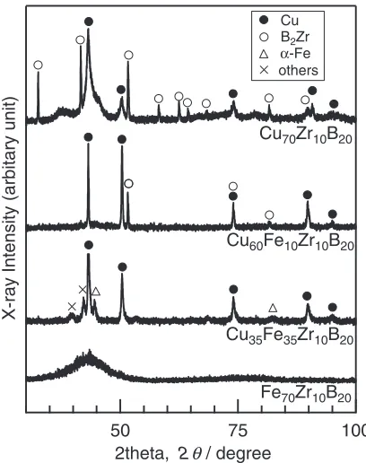
Cu60Fe10Zr10B20, and Cu70Zr10B20 alloys. The XRD patterns
in Fig. 2 correspond to the melt-spun ribbons of Cu70Zr10B20,
Cu60Fe10Zr10B20, and Cu35Fe35Zr10B20 alloys, together with
a melt-spun ribbon of Fe70Zr10B20 alloy as a reference.2,6)
The XRD pattern of the Fe70Zr10B20 melt-spun ribbon
shows broad peaks typical for an amorphous single phase, while such peaks cannot be seen for the Cu70Zr10B20,
Cu60Fe10Zr10B20, and Cu35Fe35Zr10B20 alloys. In melt-spun
ribbons of Cu70Zr10B20, Cu60Fe10Zr10B20, and Cu35Fe35
-Zr10B20, fcc-Cu is the main constituent phase. A composite
structure comprising fcc-Cu and B2Zr was formed in the
Cu70Zr10B20 alloy. The replacement of Cu by Fe suppresses
the B2Zr formation and promotes the formation of a
body-centered-cubic (bcc)-Fe phase. This can be seen in the XRD pattern of Cu60Fe10Zr10B20, which shows peaks
correspond-ing to fcc-Cu and B2Zr, and that of Cu35Fe35Zr10B20, which
shows peaks corresponding to fcc-Cu, bcc-Fe, and minor unknown phases. The constituent phases present in the CuFeZrB alloys strongly depend on the composition. Melt-spun ribbons of Cu-rich alloys mainly consisted of fcc-Cu and minor phases of bcc-Fe and B2Zr intermetallic
compounds, while bcc-Fe and B2Zr phases were not observed
in the Fe-rich Cu70¹xFexZr10B20alloy (x=70, 60 and 50).2,6)
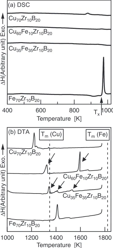
Amorphous phase formation and liquid phase separation were also investigated by thermal analysis (Fig. 3). In the DSC curves (Fig. 3(a)), thermal crystallization of an amorphous phase is indicated by the characteristic exother-mic peaks. A typical example is indicated by the black arrow in the DSC curve for a melt-spun ribbon of Fe70Zr10B20
alloy.2,6) These peaks cannot be seen in the alloys of Cu70Zr10B20, Cu60Fe10Zr10B20, and Cu35Fe35Zr10B20. This
data, along with the XRD patterns presented in Fig. 2, indicate that an amorphous phase was not formed in the melt-spun ribbons of these alloys. The DTA curves corresponding to cooling the samples from 1773 to 1000 K at a rate of 0.33 Ks¹1were shown in Fig. 3(b). The Cu
60Fe10Zr10B20and
Cu35Fe35Zr10B20 alloys show some exothermic peaks
corre-during rapid solidification. Figure 4 shows the trans-scale observation of melt-spun ribbons of Cu35Fe35Zr10B20
(Figs. 4(a)4(d)) and Cu60Fe10Zr10B20 (Figs. 4(e)4(h))
alloys obtained by optical microscopy (OM) and SEM-BEI, where “trans-scale observation” means the combination of images at various magnifications by using OM, SEM, TEM, HVEM, HREM, and so on.6) The observation direction in OM, SEM, EPMA and TEM was perpendicular to the ribbon surface. In the case of both the alloys, typical structures formed through liquid phase separation could not be seen either at the millimeter or at the 100 µm scale (Figs. 4(a), 4(b), 4(e), and 4(f )). In the case of the Cu35Fe35Zr10B20alloy,
the SEM-BEI images (Figs. 4(c) and 4(d)) show the formation of an entangled duplex structure composed of dark and bright gray regions with structures of the order of 10100 µm. As shown in Fig. 4(d), dark gray globules embedded in a bright gray matrix and bright gray globules embedded in a dark gray matrix can be seen. The size of globules is of the order of 1 µm. In contrast, the formation of an entangled duplex structure with 1-µm-sized globules can be seen in the case of the Cu60Fe10Zr10B20 alloy (Figs. 4(g)
and 4(h)). In this case, the size of dark and bright gray regions was slightly larger than those of the Cu35Fe35Zr10B20
alloy. Figure 5 shows trans-scale observation of of melt-spun ribbons of the Cu70Zr10B20alloy obtained by OM (Figs. 5(a)
and 5(b)), SEM-BEI (Figs. 5(c) and 5(d)), and TEM-BF (Fig. 5(e)) images. The OM images show the difference in the surface morphologies of the quaternary CuFeZrB and ternary CuZrB alloys. SEM-BEI images show black precipitates with a faceted structure embedded in a white gray matrix. The precipitates can be attributed to B2Zr. Figure 5(e)
shows the TEM-BF image corresponding to the white gray matrix from the SEM images. Coarse crystalline grains larger than 1 µm are indicated by the letter A, and a typical dendritic structure can be seen. These coarse grains can be identified as crystalline Cu with an fcc structure, based on the SAD pattern (Fig. 5(eA)). The occurrence of a liquid phase separation cannot be detected in ternary CuZrB alloy.
Figure 6 shows the EPMA analysis of the duplex structure in Cu35Fe35Zr10B20 (Figs. 6(a)6(e)) and Cu60Fe10Zr10B20
regions are also enriched in Zr and B (Figs. 6(d), 6(e), 6(i), and 6(j)), which are absent in the Cu-rich regions. SEM-BEI images under higher magnification (Figs. 4(d) and 4(h)) show spherical regions (globules) embedded in an entangled matrix. EPMA analysis and SEM observation result (the spherical shape of the globules, as well as their smooth interface with two phases in an entangled duplex structure), indicate the liquid phase separation with FeZrB-rich and Cu-rich regions.
Figure 7 shows the BF images and the corresponding SAD patterns for the melt-spun ribbons of Cu35Fe35Zr10B20
(Figs. 7(a)7(d)), Cu60Fe10Zr10B20 (Figs. 7(e)7(h)) alloys,
obtained by TEM. In the Cu35Fe35Zr10B20alloy, BF images
show globules as indicated by the letter B in Fig. 7(a) and
the letter C in Fig. 7(b). The SAD pattern obtained from the white matrix (indicated by the letter A in Fig. 7(a)) can be attributed to the [001] of fcc-Cu (Fig. 7(c)). In contrast, Debye rings can be seen in the SAD pattern (Fig. 7(d)) obtained from the globule indicated by the letter B in
Fig. 4 Trans-scale observation of melt-spun ribbon in Cu35Fe35Zr10B20 (a)(b)(c)(d), and Cu60Fe10Zr10B20 (e)(f )(g)(h) alloys. (a)(b)(e)(f ) OM images, and (c)(d)(g)(h) SEM-BEI images.
Fig. 1 Outer appearance of ingots obtained by arc melt method (a) and melt-spun ribbon of Cu35Fe35Zr10B20(b), Cu60Fe10Zr10B20(c), Cu70Zr10B20(d) alloys.
X-ray Intensity (arbitary unit)
100 75
50
2theta, 2θ / degree
Cu35Fe35Zr10B20 Cu60Fe10Zr10B20
Cu70Zr10B20
Fe70Zr10B20
Cu
α-Fe
B2Zr
others
[image:3.595.307.545.302.673.2] [image:3.595.66.270.305.563.2]Fig. 7(a). Rather than single-crystalline contrast, the globules show polycrystalline structure, as indicated by the letter C in Fig. 7(b). Based on the position of the Debye rings, the constituent phases of the globules can be attributed to the bcc-Fe and unknown phases. The polycrystalline globules embedded in the fcc-Cu matrix can also be seen in the Cu60Fe10Zr10B20alloy. This is indicated by the letters E and F
in the BF images (Figs. 7(e) and 7(d)), from the SAD pattern (Fig. 7(g)) obtained from the letter D in Fig. 7(e) and that (Fig. 7(h)) from the index E in Fig. 7(e). In Fe-rich alloys, e.g., Cu70¹xFexZr10B20 (x=50 and 60), single crystalline
fcc-Cu globules embedded in FeZrB-based metallic glass were obtained.2,6) The globules in the Fe-rich and Cu-rich CuxFe70¹xZr10B20 alloys exhibit a significant difference in
the size and the constituent phases. The results of both the trans-scale observation, EPMA and TEM analyses indicate that liquid phase separation promoted the formation of entangled duplex structures on the order of 10 µm, and
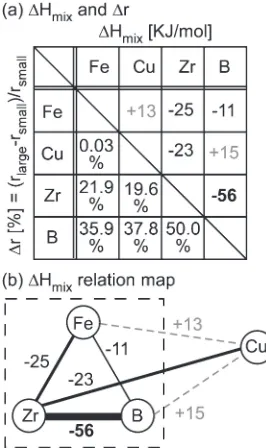
micro-alloys.30,31) Figure 8 summarizes ¦H
mix32,33) and ¦r34) of
each constituent element in quaternary CuFeZrB alloys, where ¦r is defined by the difference of their respective Goldschmidt atomic radii (¦r=(rlarge¹rsmall)/rsmall). Based
on Fig. 8(a), the¦Hmixrelation map can be written as shown
in Fig. 8(b). The repulsive relationship between FeCu and BCu, and the large attractive relationship between ZrB indicates the separation of FeZrB-based and Cu-based liquids after the liquid phase separation. This prediction is in good agreement with the EPMA analysis (Fig. 6). The large negative ¦Hmix and large¦ramong Fe, Zr, and B indicate
their high GFA in ternary FeZrB alloy system when mixed, and hence, the Fe70Zr10B20alloy shows an amorphous single
phase (see Figs. 2 and 3). On the other hand, the quantity of Cu-rich liquid in CuxFe70¹xZr10B20 alloys increased with an
increase in the value of x. The heat release caused by the crystallization of Cu-rich liquid during rapid solidification in the Fe-rich CuFeZrB alloys is too small to induce the crystallization of FeZrB-based liquid or amorphous phases, resulting in the formation of Cu crystalline globules dispersed in FeZrB amorphous alloys. In contrast, in CuxFe70¹xZr10B20 (x=35, 60, and 70) alloys, the heat
released during the cooling of melt enhances the solid-ification and/or crystallization of the FeZrB-based liquid or amorphous phase, resulting in the formation of poly-crystalline FeZrB-based globules.
4.2 Microstructural differences between Fe-rich and Cu-rich quaternary CuFeZrB alloys
The SEM images (Figs. 4(c), 4(d), 4(g), and 4(h)) and EPMA analysis (Fig. 6) show the formation of entangled duplex structures of the order of 10 µm in both the Cu35Fe35Zr10B20 and the Cu60Fe10Zr10B20 alloys. The size
of the globules varied widely, ranging from the micro- to the nanoscale (1 µm to 100 nm), as shown in the magnified SEM (Figs. 4(c), 4(d), 4(g), and 4(h)) and TEM (Figs. 7(a), 7(b), 7(e), and 7(f )) images. The identification of some minor phases could not be achieved; however, the present trans-scale observations clarified the occurrence of liquid phase separation during rapid solidification. Figure 9 shows typical examples of (a) one-step liquid phase separation and (b) multi-step liquid phase separation. The entangled duplex structure and the variations in the size of globules can be explained in terms of multi-step liquid phase separation.
Δ
H(Arbitrary unit) Exo.
Temperature [K] x
1800 1600
1400 1200
1000
Temperature [K] Fe70Zr10B20
Cu35Fe35Zr10B20 Cu60Fe10Zr10B20
Cu70Zr10B20
Tm (Cu) Tm (Fe)
[image:4.595.76.261.72.477.2]In the Fe-rich alloys (Cu70¹xFexZr10B20 (x=50 and 60)),
the entangled duplex structures could not be seen, and nanocrystalline fcc-Cu globules, dispersed in FeZrB-based metallic glasses, were formed during rapid solidification.2,6) These nanocrystalline globules, with diameters of the order of 10 nm, could not be obtained in the Cu-rich Cu60
-Fe10Zr10B20alloys. The formation mechanism of
micrometer-sized entangled duplex structures and the differences in microstructure between the Fe-rich and Cu-rich alloys can be explained by the model of multi-step liquid phase separation; however, the other mechanism can be considered to affect the rapidly solidified structure.
Fig. 6 EPMA analysis of melt-spun ribbon in Cu35Fe35Zr10B20 (a) and Cu60Fe10Zr10B20(b) alloys.
[image:5.595.329.524.66.590.2] [image:5.595.77.260.69.776.2]In CuxFe70¹xZr10B20 (x=35, 60, and 70) alloys, the
formation of entangled duplex structure from the macro-scopic view point (on the order of 10100 µm) and that of globules from the microscopic view point (on the order of 1 µm) was observed. The formation of the globules can be explained by the liquid phase separation and surface energy of liquids; for minimizing the surface energy and superficial area, a separated liquid phase with a spherical shape formed and solidified during cooling, resulting in the formation of globules. The formation of an entangled duplex structure can
Fig. 7 TEM BF images and corresponding SAD patterns of melt-spun ribbon in Cu35Fe35Zr10B20 (a)(b)(c)(d) and Cu60Fe10Zr10B20 (e)(f )(g)(h) alloys. (a)(b)(e)(f ) BF images, (c) SAD pattern obtained from the region indicated by the index A, (d) SAD pattern obtained from the region indicated by the index B, (g) SAD pattern obtained from the region indicated by the index D, (h) SAD pattern obtained from the region indicated by the index E.
Fig. 8 Heat of mixing (¦Hmix) and difference between the Goldschmidt atomic radii (¦r=(rlarge¹rsmall)/rsmall) of the elements in FeCuZrB alloy (a) and¦Hmixrelation map (b).
[image:6.595.110.486.69.307.2] [image:6.595.323.530.378.758.2] [image:6.595.100.233.383.607.2]be explained by the liquid phase separation with micrometer-order size and deformation of the separated liquid during the melt-spinning processes. The separated liquid with low viscosity and micrometer-order size can change their shape and be drawn out before the solidification, resulting in the formation of the entangled duplex structure. Above-mentioned microstructure formation processes in Cux-Fe70¹xZr10B20 (x=35, 60, and 70) alloys are different from
those in the Fe-rich alloys (Cu70¹xFexZr10B20 (x=50 and
60)), resulting in the microstructural differences between Fe-rich and Cu-Fe-rich quaternary CuFeZrB alloys.
Alloy systems exhibiting an amorphous phase can maintain their liquid state over a wider temperature range above the glass transition (liquid-to-glass) temperature. This allows liquid phase separation to occur repeatedly, because solidification owing to crystallization of the liquid is suppressed in alloys. Amorphous phase formation during rapid solidification is effective for obtaining finer globules and/or finer entangled duplex structures. The results showed the occurrence of liquid phase separation, while an amorphous phase formation was not detected. The difference in the size of globules of Fe-rich and Cu-rich alloys in Cu70¹xFexZr10B20 subjected to multi-step liquid phase
separation could be explained by the differences in an amorphous phase formation as well as their Cu/Fe ratios. The general criterion for the multistep liquid phase separation is not clarified now; however, the present study indicates that an amorphous phase formation is not the necessary and sufficient condition for the multistep liquid phase separation in FeCu based alloys. Further systematic research work is necessary for clarifying the dominant factors for the occurrence of multistep liquid phase separation.
5. Conclusions
Melt-spun ribbons of Cu70¹xFexZr10B20(x=35, 10, and 0)
alloys were characterized with respect to their rapidly solidified microstructure and the influence of liquid phase separation. The obtained results can be summarized as follows:
(1) Entangled duplex structures, namely marble structures, were formed in the Cr35Fe35Zr10B20 and Cu60
-Fe10Zr10B20 alloys, while such structures cannot be
seen in Fe-rich Cu70¹xFexZr10B20alloys.
(2) The formation of polycrystalline globules embedded in an fcc-Cu matrix can be seen by TEM observation. The constituent phases and microstructures of globules differed significantly in Cu-rich alloys from those of the Fe-rich alloys of Cu70¹xFexZr10B20.
(3) Amorphous phase formation cannot be detected in Cr35Fe35Zr10B20 and Cu60Fe10Zr10B20 alloys. The
rap-idly solidified microstructure of the Cu70¹xFexZr10B20
alloy strongly depends on the Cu/Fe ratio, while both the Fe-rich and Cu-rich alloys show multistep liquid phase separation during rapid solidification.
Acknowledgments
This work was supported by MEXT KAKENHI Grant-in-Aid for Young Scientists B 23760667.
REFERENCES
1) A. A. Kündig, M. Ohnuma, D. H. Ping, T. Ohkubo and K. Hono:Acta Mater.52(2004) 24412448.
2) T. Nagase, A. Yokoyama and Y. Umakoshi: J. Alloy. Compd. 494 (2010) 295300.
3) B. J. Park, H. J. Chang, D. H. Kim and W. T. Kim:Appl. Phys. Lett.85 (2004) 63536355.
4) N. Mattern, U. Kuehn, A. Gebert, T. Gemming, M. Zinkevich, H. Wendrock and L. Schultz:Scr. Mater.53(2005) 271274.
5) I. Yamauchi, T. Irie and H. Sakaguchi:J. Alloy. Compd.403(2005) 211216.
6) T. Nagase, A. Yokoyama and Y. Umakoshi:Mater. Trans.47(2006) 11051114.
7) A. A. Kündig, M. Ohnuma, T. Ohkubo, T. Abe and K. Hono: Scr. Mater.55(2006) 449.
8) E. S. Park and D. H. Kim:Acta Mater.54(2006) 2597.
9) E. S. Park, E. Y. Jeong, J. K. Lee, J. C. Bae, A. R. Kwon, A. Gebert, L. Schultz, H. J. Chang and D. H. Kim:Scr. Mater.56(2007) 197. 10) N. Mattern, T. Gemming, G. Goerigk and J. Eckert: Scr. Mater.57
(2007) 2932.
11) T. Nagase and Y. Umakoshi:J. Alloy. Compd.495(2010) L1L4. 12) Y. Nakagawa:Acta Metall.6(1958) 704711.
13) K. Iwase, M. Okamoto and T. Amemiya: Sci. Rep. Tohoku Univ.14 (1937) 618640.
14) P.-A. Lindqvist and B. Uhrenius:Calphad4(1980) 193200. 15) Y. Chuang, R. Schmid and Y. A. Chang:Metall. Trans. A15(1984)
19211930.
16) A. Munitz:Metall. Trans. B18(1987) 565575.
17) S. P. Elder, A. Minutz and G. J. Abbaschian:Mater. Sci. Forum50 (1989) 137150.
18) G. Wilde, R. Willnecker, R. N. Singh and F. Sommer: Z. Metallkd.88 (1997) 804809.
19) G. Wilde and J. H. Perepezko:Acta Mater.47(1999) 30093021. 20) S. Amara, A. Belhadj, R. Kersri and S. H. Thibaults: Z. Metallkd.90
(1999) 116123.
21) R. Bhattacharya, B. Majumdar and K. Chattopadhyay: J. Electron Microsc. Suppl.48(1999) 10471054.
22) X. Y. Lu, C. D. Cao and B. Wei:Mater. Sci. Eng. A313(2001) 198 206.
23) C. P. Wang, X. J. Liu, I. Ohmura, R. Kainuma and K. Ishida:Science 297(2002) 990993.
24) S. Bysakh, K. Chattopadhyay, T. Maiwald, R. Galun and B. L. Mordike:Mater. Sci. Eng. A375377(2004) 661665.
25) K. Taguchi, H. Ono-Nakazto and T. Usui:ISIJ Int.46(2006) 2932. 26) T. Nagase, A. Yokoyama and Y. Umakoshi: J. Alloy. Compd. 509
(2011) 11781186.
27) T. Kozieł, Z. Kędzierski, A. Zielińska-Lipiec and K. Ziewiec: Scr. Mater.54(2006) 19911995.
28) J. He, J. Z. Zhao and L. Ratke:Acta Mater.54(2006) 17491757. 29) T. Nagase, A. Yokoyama and Y. Umakoshi: J. Alloy. Compd. 509
(2011) 11781186.
30) A. Inoue:Acta Mater.48(2000) 279306.
31) A. Inoue: Bulk Amorphous Alloys, (Trans Tech Publications, Zurich, 1998).