Munich Personal RePEc Archive
Evaluating the effect of upside and
downside slope on flow hydraulic in
cylindrical overflows by using Flow 3D
software
Mostofi, Kasra Hossein and Kolbadi nezhad, Rooholla
M.Sc, Civil Engineering, Kish International Branch, Islamic Azad
University, Kish, Iran, M.Sc, Civil Engineering, Kish International
Branch, Islamic Azad University, Kish, Iran
10 November 2016
Online at
https://mpra.ub.uni-muenchen.de/91638/
Evaluating the effect of upside and downside slope on flow
hydraulic in cylindrical overflows by using Flow 3D software
Kasra Hossein Mostofi, Rooholla Kolbadi nezhad
M.Sc, Civil Engineering, Kish International Branch, Islamic Azad University, Kish, Iran.
M.Sc, Civil Engineering, Kish International Branch, Islamic Azad University, Kish, Iran.
Abstract
:Features and behavior of flow in hydraulic structures is one of the complex phenomena. Cylindrical overflow is a simple hydraulic structure which is used for energy dissipation, control and flow measurement. Hereof the sharp, wide and climactic edges overflows are used commonly. In water transmission and distribution systems, cylindrical overflows and crest- circular overflows because of being affordable and ease of fabrication compared with other overflows can be used for measurement of flow rate, evacuation buildings of flow water and controlling the level of water in canals and reservoirs. The water flow on overflow of dams and used overflows in water supply and sewage networks are some cases that a design engineer is in contact with them.
Keywords
: upside and downside slope, cylindrical overflow, flow3dIntroduction
:Major conducted researches about cylindrical overflows had been as physical models hitherto. Today the possibility of doing researches as mathematical model has been provided according to increasing the memory and speed of computers and developing of suitable three-dimensional software. One of the suitable models for making the three-dimensional flows as the model is Flow-3D model. The mentioned software is one of the strongest available software and has answered successfully in many cases yet. In this research was tried to evaluate the flow on cylindrical overflows by Flow-3D model and to provide suitable model [1]. The researches results of Rahmani and et al (2014) were used in order to calibration and validation of the model [2]. Using the cylindrical overflow is the flow rate measuring device meanwhile, reduces the speed and dropping the flow energy through creating turbulence along the structure. Also these kinds of overflows in few rates create beautiful view. Designing these kinds of structures is accomplished usually without necessary studies and considering to hydraulic condition in many cases and after that, the river shows negative and undesirable reaction to this kind of change including strong erosion in downside [3]. Hitherto most of done researches in this matter have been done by using physical model according to the nature of flow on cylindrical overflows. In this research the flow on cylindrical overflow has been simulation by using Flow-3D software. The results of Rahmani and et al (2015) were used in order to calibration and also validation of flow model over the cylindrical overflow [4]. So the purpose of this research is evaluating the flow hydraulic on cylindrical overflows by using mathematic model. Compound section is referred to a section the surface of which is made of several sub-sections with different flow characteristics Bahadori et al(2016) [5]. This research investigates the change of the velocity on seawall crown by considering the obstacles in different layouts and slopes Deilami et al (2016) [6]. hydraulic and creates an interaction between the main channel and floodplains, resulting in an apparent shear stress and a transverse momentum transfer Bahadori et al(2016) [7].
The increase in population in coastal areas increases the importance of protection of the coasts and ports. Iran has several thousand kilometers of coastline and must provide Deilami et al (2016) [8, 9]. Sea walls were 22, 27, 32, 39 degrees, respectively and had the roughness heights on wall surface were 15 cm, 20 cm and 30 cm. Moreover, four types of roughness layouts on the wall surface were investigated Ebrahimi et al (2016) [10]. A wide range of studies have been conducted inaforemention parameters is followed by the complexity connection with symmetrical compound rectangular of the hydraulic flow Bahadori et al(2016) [11].
Breakwaters are structures which are constructedin order to create peace in a pool of ports, to preventport erosion, and to protect the shipping channel Iman mifoor et al (2016) [12]. Apparent shear stress and transverse momentum transfer resulted from it play important roles in the calculation of flow rate and secondary flows to identify and control the sediment transport mechanism in order for protecting coasts, organizing rivers, designing a stable channel, analyzing scouring as well as transmitting the contamination Bahadori et al(2016) [7]. The main differentiation stages compound with regular and typical sections of the same phenomenon is also hence the use of conventional hydraulic relationships associated with the regular channels, the compound channels, in combination with a significant incidence of errors Behdarvandi askar et al (2013) [13].
Research Methodology:
possible presently. Mathematic and physical models are used for doing basic researches and extraction of general laws or regulating of hydraulic phenomena and are confirmed for accuracy of the models results by field data. A time model has good accuracy which has been calibrated with field and laboratory data, too.
Mathematic models
Mathematic model is a model that is created based on govern relations on a phenomenon, so just those hydraulic phenomenon can be turned to a mathematic model that firstly the regnant mathematic relations to that phenomenon has been extracted and secondly there is acceptable method and suitable device for solving these relations.
Benefits that mathematical model has than to physical model are as follows:
A) Adoption of obtained results is too fast.
B) Studying the effect of each one of variables on that specific phenomenon is east and fast.
C) After creating mathematic model it can be used for different projects with different initial and boundary conditions, While if physical model is made, it is extensible just for that model sample.
D) Doing mathematic model is possible by a person, too; while doing physical models is as a group.
E) Providing mathematic models are cheaper than physical models according to mentioned benefits development of mathematic models and usage of that has been considered by engineers.
Fluent software
In general, methods of predicting a physical phenomenon are divided into two major categories:
1) Experimental method (laboratory)
2) Theory method
In theory method, first by observation of physical phenomenon, the corresponding differential equations are expressed and after that, regnant algebraic equations to the problems are tended. A problem that exists is unlike phenomenon which suitable mathematic model has been provided for them (such as laminar flow), phenomenon exists that suitable mathematic model has been not found for them (such as two-phase flow).
Here, numerical methods are used as a third solution for solving fluid flow problems. So in another classification, the fluid dynamics can be divided to three parts:
1. Experimental Fluid Dynamics 2. Fluid dynamics theory
3. Computational Fluid Dynamics
Analyzing systems including fluid flow, heat transfer and associated phenomena, such as chemical reactions, based on computer simulation. CFD methods can be conducted using in-house solvers in the case of facing with a specific type of problem, for example Navier-Stokes equations are numerically solved for 3D simulations of environmental flows by Jalali et al (2014) [14]. However, it is common practice and cost efficient to use flexible general-purpose CFD software packages like Fluent to approach problems similar to this study. Hamedi et al. (2016) have been used Finite Volume method in Fluent Software to simulate low discharge flow in complicated geometries [15]. They compared their results with physical model outcomes which reported by Hamedi et al. (2014) and noted that the applied numerical model is able to successfully simulate the flow pattern and velocity vectors [16].
CFD is very capable method so that covers a wide range of industrial and non-industrial usages, some examples include:
Aircraft and vehicles aerodynamics, thermal exchanger, hydrodynamic of ships, reactive flows, installations, central heating and air conditioning of powerhouse, combustion in internal combustion engines and gas turbines....
Simple algorithms for solving incompressible viscous flow:
If we discrete the equation (6-3) by a customize and suitable numerical method we find an algebraic equation for any node in the network computing that in total covered up an equation system and we can get unknowns means speeds by solving that.
Now if we show as a whole the algebraic equation for any arbitrary point in the network in following:
Where in subscript of i shows desired direction in p point for example for for i=2 means speed in
direction of y in s and p points shows sentences collection which were calculated in previous time step and volumetric force sentences or other variables at the same time step which totally make fountain sentence and finally L show neighborhood point of p. consider that pressure gradient discrete figure has been entered symbolic which is for emphasize on being independent of solution from way of local discretization.
Equation cannot be solved directly because of nonlinear being of connection of regnant equations which is
for the reason that A coefficients and probably fountain sentence includes variable, so repeat
methods are suitable option for solving the resulting system. If evaluating problem be a transient problem, repeats should be done so much in each time step that the system become satisfied and then transfer to next step.
of and variables be completely verity in equations. If equations don’t have transient state, we don’t have time ring and system becomes converge just by repetitive solving. Consider that in two previous states (the transient problem which steady state solution is only important and so we don’t make system completely convergent in each time step and solving the sustainable equations) just final solution is reliable and middle solutions are worthless.
So the repeats are done in each time step which the system coefficients and fountain sentence are calculated in each of them and a system with constant coefficients is obtained and then this system is solved with a repetitive method of solving system or direct method and we are moved to next repeat and finally we are moved to next step after convergence. A repeat which the system coefficients and fountain sentence are solved in it, is called external repeat and repeats that are given to solving the system, are called internal
repeat. If we show the time step with n and external repeats with m and internal repeats with , the
solving process will be as follow:
So we put aside the solution of superscript n+1 from equation and rewrite by introducing the m superscript
which shows external repeat. Consider that is estimation for at the end of external repeat ring.
The right side phrase of equation is calculated from amounts of field variables in external repeat means m-1.
Solving algorithm is as follows:
1. The solution begun as a first guess for and by help of amounts.
3. We form pressure correction Poisson's equation by help of and solve.
4. Calculated the amount of correction speeds.
5. Calculated new pressures.
6. Return to step 2 until amount of corrections become trivial.
7. Beginning of time step then return to stage 1.
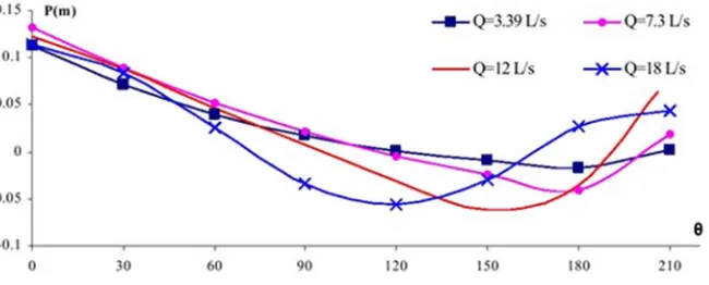
As it is seen, shapes of charts are similar for different ratios of dcrest/R and the location of point separation
get closer to overflow crest by increasing the ratio of dcrest/R. in other word, for a specified diameter; whatever the flow rate is increased causes to increasing the submergence and the separation point get closer to crest. In figure 5-4 still there is vacuity in few rates till the angle range of 210 and after that the pressure become equal to atmosphere pressure on the overflow surface and the separation occurs.
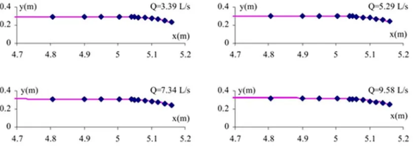
[image:7.612.98.505.371.518.2]The laboratory measuring data is used for comparing calculating results in order to evaluating the capability of model. As it is seen, results show a suitable adapted model with laboratory information (Esmaeili and et al 2010). The maximum difference is about 2.5%. Existing difference is mainly related to fluctuations of calculated water level in numerical model. The wall standard functions (in k-e turbulence model) is not capable to exact predict of this effects because of strong gradient of pressure on the overflow surface. Therefore, it has error about 10%. But generally the performance of numerical model is satisfactory.
Figure 1 comparing the result of free level in different measured rates
Figure 2 pressure contribution in different point of overflow rate for various rates
Conclusion
In this research, the flow numerical simulation on cylindrical overflow is done by using physical model condition and by using Flow-3D software and by using finite volume method and Navier-Stokes equations
in order to solving the flow field. The
k
model is used in order to simulation of flow turbulence. Itwas determined based on this:
1- The Flow-3D software can be used for cylindrical overflow hydraulically studies in order to reducing laboratory operations, saving in financial and human resource.
2- The flow speed in crest surface is predicted zero by using fluent software and reaches to its maximum value in a very short distance, because of forming the boundary layer on the surface of overflow crest.
3- The speed profiles on the crest, pressure on the crest and surface of passing water over the circular crest overflow which was simulated by using the software, has excellent agreement with laboratory data which is the validation of the model in turn, too.
4- Results showed, for a constant flow, the amount of coefficient rate is reduced by increasing the overflow diameter.
Reference
:[1] H. Chanson and J. S. Montes, "Overflow characteristics of circular weirs: Effects of inflow
conditions," Journal of irrigation and drainage engineering, vol. 124, pp. 152-162, 1998.
[2] F. Rahmani, F. Razaghian, and A. Kashaninia, "High Power Two-Stage Class-AB/J Power
Amplifier with High Gain and Efficiency," 2014.
[3] M. Ketabdar, "Numerical and Empirical Studies on the Hydraulic Conditions of 90 degree
converged Bend with Intake," International Journal of Science and Engineering Applications, vol.
[4] F. Rahmani, F. Razaghian, and A. Kashaninia, "Novel Approach to Design of a Class-EJ Power
Amplifier Using High Power Technology," World Academy of Science, Engineering and
Technology, International Journal of Electrical, Computer, Energetic, Electronic and Communication Engineering, vol. 9, pp. 541-546, 2015.
[5] S. Bahadori and M. B. Askar, "Investigating the Effect of Relative Width on Momentum Transfer
between Main Channel and Floodplain in Rough Rectangular Compound Channel Sunder Varius
Relative Depth Condition," Open Journal of Geology, vol. 6, p. 225, 2016.
[6] M. Deilami-Tarifi, M. Behdarvandi-Askar, V. Chegini, and S. Haghighi-Pour, "Effect of Slope,
Size, and Arrangement of Roughness of Sea Wall on Overtopping of Random Waves,"
International Journal of Biology, Pharmacy and Applied Sciences, vol. 4, pp. 1026-1034, 2015.
[7] S. Bahadori and M. B. Askar, "Investigating the Effect of Latitudinal Slope of Floodplain and
Relative Roughness on Apparent Shear Stress in Symmetric Compound Rectangular Channels
with Various Relative Width," Journal of Engineering and Applied Sciences, vol. 11, pp. 57-62,
2016.
[8] M. Deilami-Tarifi, M. Behdarvandi-Askar, V. Chegini, and S. Haghighi-Pour, "Modeling of the
Changes in Flow Velocity on Seawalls under Different Conditions Using FLOW-3D Software,"
Open Journal of Marine Science, vol. 6, p. 317, 2016.
[9] M. Ketabdar and A. Hamedi, "Intake Angle Optimization in 90-degree Converged Bends in the
Presence of Floating Wooden Debris: Experimental Development," Florida Civ. Eng. J, vol. 2,
pp. 22-27.2016, 2016.
[10] A. Ebrahimi, M. B. Askar, S. H. Pour, and V. Chegini, "Investigation of Various Random Wave
Run-Up Amounts under the Influence of Different Slopes and Roughnesses," Environment
Conservation Journal, vol. 16, pp. 301-308, 2015.
[11] S. Bahadori and M. B. Askar, "Investigating the Effect of Relative Depth and Relative Roughness
on Momentum Transfer in Symmetric Rectangular Compound Channels with Varius Relative
Width," International Journal of Hydraulic Engineering, vol. 5, pp. 1-8, 2016.
[12] I. Mifoor, M. B. Askar, and S. H. Pour, "On the Investigation of Basic Parameters of Designing
Protective Layer of the Offshore Breakwaters at Iran’s Kharg Island," International Journal of
Recent Scientific Research, vol. 7, pp. 9821-9823, 2016.
[13] M. B. Askar and M. F. Moghadam, "Momentum Attraction by Flood Plains in Compound
Channel," Journal of Engineering and Technology, vol. 2, pp. 7-15, 2013.
[14] M. Jalali, N. R. Rapaka, and S. Sarkar, "Tidal flow over topography: effect of excursion number
on wave energetics and turbulence," Journal of Fluid Mechanics, vol. 750, pp. 259-283, 2014.
[15] A. Hamedi, M. Hajigholizadeh, and A. Mansoori, "Flow Simulation and Energy Loss Estimation
in the Nappe Flow Regime of Stepped Spillways with Inclined Steps and End Sill: A Numerical
Approach," Civil Engineering Journal, vol. 2, pp. 426-437, 2016.
[16] A. Hamedi, A. Mansoori, A. Shamsai, and S. Amirahmadian, "Effects of End Sill and Step Slope