The Role of Foaming Agent in Structure and Mechanical Performance
of Al Based Foams
Aleksandra V. Byakova
1, Svyatoslav V. Gnyloskurenko
1;2;*, Alexander I. Sirko,
Yuliy V. Milman
1and Takashi Nakamura
21Institute for Problems of Material Science, Ukrainian National Academy of Sciences,
3 Krzhyzhanivs’ky Str., Kyiv 03142, Ukraine
2Institute of Multidisciplinary Research for Advanced Materials, Tohoku University, Sendai 980-8577, Japan
The effect of the novel foaming agent, calcium carbonate in comparison with the conventional titanium hydride on structure and energy absorbing ability of the aluminium based foams was studied. Mechanical testing Alporas foams of Al and wrought alloy Al-5.5Zn-3Mg-0.6Cu-0.5Mn (similar to alloy 7075) doped by small amount (<0:6mass%) of Sc and Zr was undertaken under compression with static strain rate of
1:5103s1. The influence of Ca additive on the cell wall structure and deformation behaviour of two kinds of the foams was recognised.
Significant advantages in mechanical performance of the aluminium foams processed with CaCO3were found and attributed to fine cellular
structure and favourable microstructure of the cell wall material. [doi:10.2320/matertrans.47.2131]
(Received February 28, 2006; Accepted May 9, 2006; Published September 15, 2006)
Keywords: Al based foam, carbonate foaming agent, cell wall microstructure, mechanical properties
1. Introduction
Lightweight metallic foams have alluring potential for different sectors of industrial application due to the unique combination of low density and novel physical and mechan-ical properties. In particular, remarkable absorbing ability of aluminium foams offers significant performance gains for crash protection of vehicle and other applications where effective utilisation of impact energy is required. Despite of the several models1–6) based on the idealised cellular
structure have been proposed, actual profile of the mechan-ical properties for real Al-foams is recognised to be far from that predicted theoretically. The reason of this discrepancy is a mesoscopic heterogeneity in density and other structural imperfections including cell morphology (thickness, curva-ture, length, etc.) of real foams. A significance of the composition and microstructure of a cell wall material is still largely ignored despite its known crucial role in performance of the corresponding bulk material. This problem becomes increasingly pronounced when foaming processes are per-formed with the gas-releasing agent and other additives that produce a foamed alloy, which differs greatly from the matrix alloy. Only a few attempts have been undertaken to highlight significance of the cell wall microstructure in mechanical response of metallic foams made with conventional titanium hydride.7,8)The investigations of the cell wall microstructure
performed with calcium carbonate as promising alternative foaming agent9)and its influence on mechanical behaviour of
foams are few in number.8) The present paper aims to
illuminate the role of the key parameters of cells above in an energy management of Alporas foams processed with coated calcium carbonate (CaCO3) comparatively to those of conventional titanium hydride (TiH2).
2. Experimental
2.1 Materials and experimental procedure
Pure aluminium and wrought Al alloy Al-5.5Zn-3Mg-0.6Cu-0.5Mn (similar to alloy 7075) doped additionally by small amount (<0:6mass%) of Sc and Zr, assigned here as ZAM alloy, were chosen as matrix materials. Foaming proc-ess was carried out following Alporas like rout10)(Table 1) in which either titanium hydride, TiH2(1 mass%) with mean particle size of 60mm or calcium carbonate, CaCO3 (2 mass%) with a mean particle size of 8mm were employed as the foaming agents (FA). To facilitate the dispersion of CaCO3powder over the melt it was coated with CaF2by the ion-exchange method.9) Granular calcium (1 mass%) was
introduced into Al melt in graphite crucible to enhance its viscosity although ZAM alloy was foamed either with admixing Ca or without it to illuminate its influence on the mechanical performance of the foams. Foaming temperature was held close to the melting point of matrix Al alloys (Table 1). After cooling foamed blocks were sectioned by an electro-discharge machining.
2.2 Investigation of structure and mechanical testing of
foamed samples
[image:1.595.307.549.346.434.2]The foams were characterised by their density, cell morphology and cell wall microstructure. The density was measured by weighing a sample of known volume and then
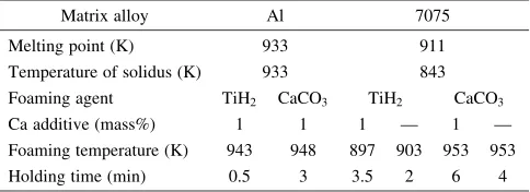
Table 1 Experimental conditions of the foaming process.
Matrix alloy Al 7075
Melting point (K) 933 911
Temperature of solidus (K) 933 843 Foaming agent TiH2 CaCO3 TiH2 CaCO3
Ca additive (mass%) 1 1 1 — 1 —
Foaming temperature (K) 943 948 897 903 953 953
Holding time (min) 0.5 3 3.5 2 6 4
*Corresponding author, E-mail: [email protected]
relative density was defined by the ratio=s(whereands
correspond to the density of foam and solid, respectively). Porosity content was derived from the relation¼1=s. Cell morphology including cell size and shape was measured by using scanned images of more than 150 cells.
Microstructure of the cell wall and cell face was analysed
by X-ray diffraction (XRD) analysis by using CuK
-radiation as well as by optical microscopy and scanning electron microscopy (SEM) supplied with X-ray detectors (EDX and EPMA). Due to the difficulty in distinguishing the phase composition of the cell wall and that of the cell face XRD analysis was applied using a step procedure. The original foamed sections with hollow cells were first analysed. Then foam sections were impregnated with opaque epoxy resin allowing only the composition of the cell wall material to be analysed.
Deformation behaviour of Al alloy foams was examined under uniaxial compression tests under static strain rate of 1:5103s1 performed on the prismatic specimens with a height to thickness ratio ranged from 1.5 to 3. Minimum dimension of the specimen was seven times larger than the cell size to avoid size effect.11)
3. Results and Discussion
3.1 Microstructure examination
Figure 1 shows the typical cellular structure of ZAM foams processed with TiH2 and CaCO3. Both foams have cells of spherical shape although mean cell size for CaCO3 -foams (D1{1:5mm) is found to be at least two times smaller than for TiH2-foams.
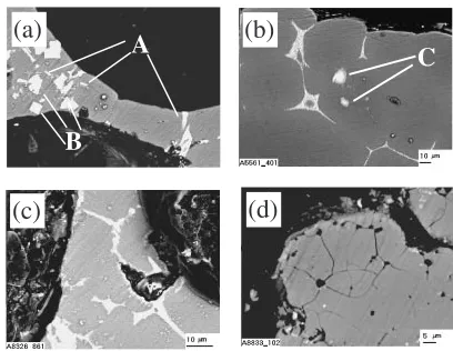
The cell walls for both kinds of Al foams consist of coarse
-Al dendrites (A) rounded by a network of the eutectic domains (B, C) as shown in Figs. 2(a), (b).8)SEM image and
EDX element distribution map testify that the latter com-poses with Al+Al4Ca+Al3Ti (B) for TiH2-foam (Fig. 2(a)) but it consists of Al+Al4Ca (C) for CaCO3-foam (Fig. 2(b)). In addition, incorporated Al-Ca-Ti particles are found out in the cell wall material of TiH2-foam and the fraction volume of the brittle constituents becomes much grater compared to CaCO3-foam.
The main differences in structural features for two kinds of foams concern the cell face composition. Cell faces of TiH2 -foam are covered by light ‘‘wool blanket’’ of Al2O3 oxide crystals in which scattered oxide crystals of CaAl4O7 and AlTi3are embedded.8)Unlike above the solid skin of Al2O3 oxide decorated both by CaO particles and Al-Ca-O complex
oxides is bonded to the cell faces of CaCO3-foam.
As shown in Fig. 3(a) the cell walls of ZAM alloy foamed with CaCO3 are composed of eutectic domains (A) and randomly scattered secondary particles (B). The presence of copper, magnesium, and zinc in the domains was detected by EDX analysis. According to the evidences derived from phase diagrams12)an interdendritic network of these domains compositionally correspond to mixture of -Al and T(Al-CuMgZn) redundant phase (A) and randomly scattered secondary particles (B) correspond to Al3Sc1xZrx. This
microstructure is basically the same as that typically obtained after slow cooling of parent ZAM alloy.
When TiH2is employed as the foaming agent, dissolved Ti is largely concentrated within the domains of T(AlCuMgZn) redundant phase, resulting in formation of Al3Ti intermetallic compound (C) (Fig. 3(b)). Inhomogeneous distribution of dissolved Ti in the domains of T(AlCuMgZn) redundant phase causes the cell wall material to pronounced alloy segregation (Fig. 3(b)). The presence of brittle Al3Ti com-pound in redundant phase is expected to impair the cell wall ductility and toughness. Slight crack network propagated along the redundant phase is revealed in the cell wall material of TiH2-foam of ZAM-alloy even before loading, as shown in Figs. 3(c), (d). Moreover, Ti-rich particles rounded by Al3Ti layer are randomly distributed in the cell wall material of ZAM alloy, especially when foaming process was performed
(a)
(b)
10 mm
Fig. 1 Macroscopic view of ZAM alloy samples foamed with TiH2(a) and
CaCO3(b) with Ca addition to the melt. Porosity of the samples is 76%.
A
C
A
B
B
(a)
(b)
C
C
Fig. 2 SEM micrographs of cell walls with-Al dendrites (A) and network of the eutectic domains Al+Al4Ca+Al3Ti (B) and Al+Al4Ca (C) for Al
foams processed with TiH2(a) and CaCO3(b).
(c)
(d)
(a)
A
B
(b)
C
Fig. 3 SEM micrographs of the cell walls and cracks network (c), (d) for foams of ZAM alloy processed with CaCO3(a) and TiH2(b)–(d) with Ca
additives (a), (c) and without them (b), (d). A, B and C correspond to T(AlCuMgZn) redundant phase, Al3Sc1xZrx and Al3Ti intermetallic
[image:2.595.319.533.72.177.2] [image:2.595.66.270.74.175.2] [image:2.595.323.527.237.395.2]without Ca additive (Fig. 3(b)). These particles are presum-ably formed due to an incomplete decomposition of TiH2 foaming agent. This fact is expected because final temper-ature of the TiH2thermal decomposition is known to be too high.
When Ca was added to the melt prior foaming stage it was detected in the solid cell wall by EDX analysis. This element is accumulated over the domains of the parent redundant phase suggesting the presence of foreign Ca-based interme-tallic compounds. According to elemental distribution the latter could be mainly associated with formation of Al2 -CaZn2, Al2CaCu compounds, since they are the expected products when dissolved Ca reacts with the alloying elements, extracting them from an aluminium solid solution. This event leads to the significant deviation of the compo-sition of the cell wall material from the one of the parent conventional alloy.
Unlike to hydride-foamed alloy, solid oxide skin is assumed to cover the surface of cell face of the carbonate-foamed ZAM alloy similar to that found out for carbonate-foamed pure Al.
3.2 Mechanical performance of the foams
3.2.1 Compressive response of Al-foam
Compressive stress-strain curves typical for Al foams of comparable porosity processed with carbonate and hydride with addition of Ca are shown in Fig. 4.
The shape of the curves is similar to that reported for elastic/plastic foams of closed-cell cellular structure.1–3)All
kinds of foams give initial linear elasticity regime before general yield (yield strength: y). Beyond the yield foams
exhibit relatively long and well-defined plateau regime, which is typically associated with cells collapse that is superimposed by densification of the cell wall material. The plateau continuous up to densification strain, "D, beyond which cellular structure commences to condense completely and the stress rises steeply.3)As it is typical for closed-cell
foams, the stress rises gradually with growing the strain up to the densification. That is why plateau stress of closed-cell foams is often estimated by the stress reached up to densification, pl. This is especially justified when damage tolerance of the foams is important.
However, comparison of the stress-strain curves shows
some differences in compressive behaviour for different kinds of foams, implying the influence of the distinctive structural features of the cell wall material. As could be seen in Fig. 4(a) the slope of the stress-strain curve before yield (shown by solid and dash tangential lines and triangles in the plot) for CaCO3-foam is much greater than that for TiH2 -foam of the same porosity, implying greater elastic stiffness,
S, for CaCO3-foam. This is primary because mean cell size of CaCO3-foam is smaller at least by factor 2 compared to that of TiH2-foam. According to the relation given in Ref. 13) this difference leads to the fact that the length for gas/metal boundary per unit area for CaCO3-foam increases roughly by twice, causing the elasticity stiffness to rise up.
The second distinctive feature is attributed to the fact that slight oscillating the stress-strain curve under plateau regime (Fig. 4(b)) is visible for TiH2-foam in contrast to almost smooth plateau stress exhibited by CaCO3-foam. Stress oscillations are typically interpreted as hardening/softening sequences caused by localised brittle failure of the cell walls. Despite of dominating ductile behaviour of the conventional Alporas TiH2-foam demonstrated in Refs. 7), 14), slight hardening/softening effects can be resulted from micro-scopic compacting the cell wall material by crushing the brittle Al-Ca-Ti eutectic domains, which is superimposed upon hardening the cell walls by plastic deformation. In addition, crushing the low ductile Al-Ca-Ti-rich particles can probably stimulate the hardening/softening effects. In con-trast to that cell walls of CaCO3-foam show more ductile behaviour, suggesting higher toughness of Al+Ca eutectic domains in the cell walls than that of Al+Ca+Ti eutectic in which Al3Ti intermetallic compound is additionally present-ed besides Al4Ca compound. Indeed, direct measurements of the resistance to fracture of Al3Ti and Al4Ca intermetallic compounds should be fulfilled in advance to quantify the precise significance of difference in toughness for different kinds of eutectics.
Despite of yield strength is nearly the same for both kinds of foams, hardening rate (slope of the stress-strain curve up to densification) is higher for CaCO3-foam. This fact results in greater plateau stress, pl, for CaCO3-foam, although its densification strain,"D, is superior to that for TiH2-foam, as shown in Fig. 5. It should be noted that exact determination of ‘‘densification strain’’ and ‘‘plateau stress’’ have not yet
0.1 0.2 0.3 0.4 0
1 2 3 4 5 6
CaCO3 FA, porosity - 79%
TiH2 FA, porosity - 80%
TiH2 FA, porosity - 78%
CaCO3 FA, porosity - 76%
Nominal Stress,
σ
/MPa
Nominal Strain, ε
(b)
0.0 0.1 0.2 0.3 0.4 0.5 0.6 0.7 0.8 0
2 4 6 8 10 12 14
SCaCO 3
STiH 2
CaCO3 FA, porosity - 79%
TiH2 FA, porosity - 80%
TiH2 FA, porosity - 78%
CaCO3 FA, porosity - 76%
Nominal Stress,
σ
/MPa
Nominal Strain, ε
>
(a)
Fig. 4 Compressive stress-strain curves for Al foams of comparable porosity treated with CaCO3and TiH2FA with addition of Ca.
[image:3.595.95.503.74.215.2]been standartized, so these points are marked on the plots (Figs. 4, 7, 8) to clarify our approach in estimating these mechanical characteristics. In the present study the value of plateau strain was designated as a strain at which the slope of the plateau deviates from linearity that was described previously in details in Ref. 8).
However, the differences among the compressive behav-iour of the foams decrease with growing the porosity and they are expected to become negligible when porosity exceeds roughly 88% at which rupture of the cell wall occurs because its thickness is too small (<100mm).
There is some uncertainty related to the role of the cell face architecture in influencing the mechanical behaviour of closed cell foams especially those processed with CaCO3 foaming agent. This is because the solid oxide skin is formed on the surface of cell walls due to oxidising reaction between CO2 and molten Al. It has been declared in Ref. 3) that in closed-cell foams the stress can rise up with increasing strain up to densification because the cell faces carry membrane (tensile) stresses. From this point of view the oxide skin over cell faces could presumably affect the membrane tensile stresses since coefficient of thermal expansion,k, for oxides is roughly by an order magnitude smaller than that for Al, i.e. Al2O3 oxide possessk¼7:8106K1 whilst Al exhibits
k¼13106K1). The question is whether the oxide skins
is capable to influence the profile of mechanical properties of Al-foam when its thickness is much smaller than that of the cell wall?
Figure 6 shows the data for energy absorbing ability for Al foams processed with CaCO3or TiH2FA over the wide range of porosity. Energy of absorption was estimated by the amount of the specific energy absorbed by the foam up to densification, Apl, and measured as the corresponding area
under the stress-strain curve. It could be seen that CaCO3 foaming agent offers significant performance gains in energy absorption ability of Al foams over wide region of porosity content. This is primarily because Alporas foam processed
with CaCO3 foaming agent absorbs more energy than
conventional TiH2-foam of the same porosity, although the plateau stress for CaCO3-foam rises up not so much high, ensuring satisfactory damage tolerance to protected object. Remarkable improvement of energy management of Al foam is primary resulted from efficiency of the cell wall micro-structure.
3.2.2 Compressive response of ZAM alloy foam
Figures 7 and 8 demonstrate typical compressive stress-strain curves for ZAM alloy foams processed with CaCO3or
Fig. 5 Dependence of the mechanical parameters of Al foams treated with CaCO3or TiH2FA with addition of Ca on the porosity.
0.0
0.1
0.2
0.3
0.4
0.5
0.6
0.7
0
5
10
15
20
25
CaCO3 FA, with Ca TiH2 FA, with Ca
Nominal Stress,
σ
/MPa
Nominal Strain,
ε
Fig. 7 Compressive stress-strain curves of ZAM alloy foams with additives of Ca and processed with CaCO3or TiH2FA. Porosity is 75%.
0.0
0.1
0.2
0.3
0.4
0.5
0.6
0.7
0
5
10
15
20
25
30
CaCO3 FA, no Ca TiH2 FA, no Ca
Nominal Stress,
σ
/MPa
Nominal Strain,
ε
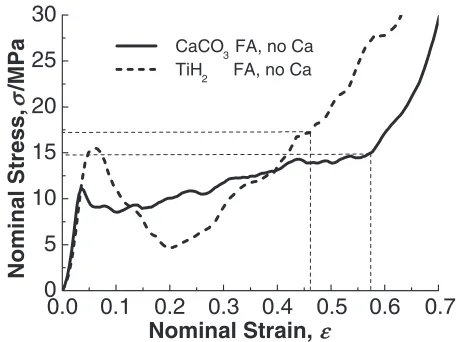
Fig. 8 Compressive stress-strain curves of ZAM alloy foams without additives of Ca and processed with CaCO3or TiH2FA. Porosity is 75%.
60 64 68 72 76 80 84 88 92 96 0.0
0.4 0.8 1.2 1.6 2.0 2.4 2.8
Porosity, %
Energy Absorption,
A pl
/MJ/m
3
CaCO
3FA
TiH
2FA
[image:4.595.53.285.71.225.2] [image:4.595.313.538.73.246.2] [image:4.595.56.283.280.438.2] [image:4.595.312.540.302.473.2]TiH2 FA with Ca addition to the melt or without it, respectively. The shape of the curves is typical for that of Al alloy foams in which the cell wall material contains brittle constituents.7,15)
All kinds of ZAM alloy foams above show rather similar elasticity stiffness and also inhomogeneous macroscopic deformation. Beyond the yield (yield stress) the foams display peak stress followed by a load softening to the plateau region at which cells collapse and condense. Moreover, the foams give significant stress oscillations superimposed upon gradual increasing stress level with increasing the strain. These deformation events indicate that brittle fracture of the cell wall contributes strongly to the geometrical collapse of the cells. Cracks being propagated initially along the domains of brittle redundant phase even before loading (Figs. 3(c), (d)) result in failure throughout the rest of the cell walls.
Pronounced differences among deformation patterns for the foams are revealed under plateau regime. High peak stress at the onset of global collapse followed by strong load drop is exhibited by TiH2-foam processed without admixture of Ca (Fig. 8), causing the plateau stress of saddle shape. Moreover, stress-strain curve for this kind of foam is fluctuated at the most, indicating the extensive brittle fracture of the cell walls. The presence of low ductile Ti-rich particle in the cell wall material is thought to result in relatively high stresses required for TiH2-foam of ZAM alloy to commence densification. In addition, these particles and also brittle Al3Ti intermetallic compounds accumulated over the do-mains of the interdendritic redundant phase (Fig. 3(b)) cause the cell wall toughness to significant impairment. Application of CaCO3 foaming agent gives remarkable improvement of deformation pattern. Figure 8 demonstrates that CaCO3 -foam processed without Ca addition shows mostly smooth stress-curve, which keeps peak-to-peak amplitude of the oscillations to minimum level.
Admixture of Ca to the melt causes the stress level of deformation patterns for both kinds of ZAM alloy foams to decrease, although the shape of the stress-strain curves remains rather similar, as shown in Fig. 7. Moreover, peak stress corresponding to the onset of the global collapse in TiH2-foam decreases significantly, resulting in smoothing saddle shape of the plateau stress. Extraction of the alloyed elements from the matrix alloy due to formation of Ca-based intermetallic compounds is thought to be the reason for decreasing the strength of cell wall material. However, the stress level of deformation pattern for TiH2-foam is lower than that for CaCO3-foam. It could be associated with impairing the toughness of the cell wall materials by brittle Al3Ti compound presented over the interdendritic network of the redundant phase and randomly scattered Ti-rich particles of low ductility the same as to that recognised in TiH2-foam of pure Al.
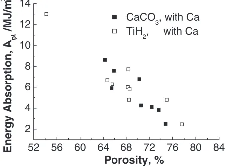
Hydride foam exhibits a significant scatter of the data for energy absorption up to densification,Apl, (Fig. 9) although it
tends to be somewhat smaller with admixture of Ca (Fig. 10). Inhomogeneous deformation at which the cells fail in brittle manner is expected to give instability of the final results. This is also stimulated by alloy segregation within the interden-dritic domains of the brittle redundant phase being presented in the cell wall material. Scattering of the data for CaCO3
-foams and especially for those processed with Ca additive is shown to be much smaller, implying better reproducibility of the results. Taking into account scattering of the data it could be seen in Figs. 9 and 10 that energy absorbing ability of CaCO3-foams tend to be nearly the same or somewhat smaller than that of TiH2-foams.
Generally, absorption energy of ZAM alloy foam (Figs. 9 and 10) is much superior to that exhibited by Al foam (Fig. 6) over a wide range of porosity. This is primarily because ZAM alloy foams give much higher yield strength and plateau stress than those of pure Al. Despite of this ZAM alloy foams demonstrate significant densification strain, "D, which is
nearly the same to that exhibited by CaCO3-foam of pure Al, shown in Fig. 5. Indeed, the difference among energy absorbing ability of ZAM alloy foam and Al foam decreases with growing porosity. However, energy absorption of ZAM alloy foam processed with Ca additive was found to remain roughly 60% higher than that of Al foam even when porosity content is as great as 94%.15)
As applied to the practical problem, energy absorbing characteristics of the CaCO3-foams is thought to be much attractive than those of TiH2-foams since they show
decreas-52 56 60 64 68 72 76 80 84
2 4 6 8 10 12 14 16 18 20
Energy Absorption,
A
pl/MJ/m
3
Porosity, %
CaCO3, no Ca TiH2, no Ca
Fig. 9 Variation of energy absorption for ZAM alloy foams without additives of Ca and processed with CaCO3or TiH2FA with porosity.
52 56 60 64 68 72 76 80 84
2 4 6 8 10 12 14
Energy Absorption,
A
pl/MJ/m
3
Porosity, %
[image:5.595.314.541.78.247.2]CaCO3, with Ca TiH2, with Ca
[image:5.595.314.540.304.472.2]ed non-homogeneity in deformation and ensure better reproducibility of the final results due to favourable micro-structure of the cell walls.
4. Conclusions
Compared to the conventional titanium hydride (TiH2), coated calcium carbonate (CaCO3) offers significant advan-tages in mechanical performance of closed cell aluminium foams produced by Alporas like route due to finely cellular structure and remarkable improvement of the cell wall microstructure. Mean cell size for CaCO3-foams (D1{ 1:5mm) is found to be at least two times smaller than for TiH2-foams over a range of porosity. Compared to CaCO3 -foams cell wall ductility and toughness of TiH2 foams are impaired by the presence of a high fraction volume of brittle constituents. In particular, the cell walls in CaCO3-foam of pure Al consist of Al dendrites rounded by a network of
Al+Al4Ca eutectic domains whereas network of Al+
Al4Ca+Al3Ti eutectic domains and incorporated Al-Ca-Ti particles are formed in the cell walls of TiH2-foam, causing the fraction volume of the brittle constituents to rise up.
In ZAM alloy foam processed with TiH2 brittle Al3Ti intermetallic compound formed additionally within interden-dritic domains of the T(AlCuMgZn) redundant phase being emerged in a matrix of Al solid solution. This redundant phase becomes modified by Ca-based intermetallic com-pound due to admixture of Ca additive. Moreover, low ductile Ti-rich particles rounded by brittle Al3Ti layer are randomly distributed in the cell wall material of ZAM alloy. These particles are presumably formed due to an incomplete decomposition of TiH2 foaming agent.
Following advantages in mechanical performance related primarily to energy absorption characteristics could be gained due to favourable microstructure of the cell walls in CaCO3-foams.
Finer cellular structure is expected to give the rise of the elastic stiffness of Al foam processed with CaCO3. More-over, CaCO3-foam of pure Al shows more ductile compres-sive behaviour than that of TiH2-foam, suggesting higher toughness of the cell wall materials for CaCO3-foam than for TiH2-foam. Despite of yield strength, y, is nearly the same for both kinds of foams, hardening rate is higher for CaCO3 -foam, resulting in greater plateau stress, pl, although its densification strain, "D, is superior to that for TiH2-foam. Because of this Al foam processed with CaCO3 foaming agent absorbs more energy up to densification, Apl, than
conventional TiH2-foam of the same porosity, although the plateau stress for CaCO3-foam rises up not so much high, ensuring damage tolerance to protected object.
Despite of both kinds of ZAM alloy foams behave in brittle manner their macroscopic deformation history is rather different. High fraction volume of brittle constituents in the
cell walls causes highly inhomogeneous macroscopic defor-mation of ZAM alloy TiH2-foams, resulting in extensive brittle fracture of cells. In contrast to this CaCO3-foams keep hardening/softening effects that are resulted from damage of the cell walls to minimum level. Stresses,yandpl, required
for densification of two kinds of ZAM alloy foams tend to decrease with Ca additive, although densification strain,"D, remains actually unchanged. Extraction of the alloying elements from matrix alloy due to formation of Ca-based intermetallic compounds is thought to be the reason for decreasing the strength of cell wall material. Generally, both kinds of ZAM alloy foams show nearly the same energy absorbing ability, although the scatter of data for CaCO3 -foams and especially for those modified by Ca additive is shown to be much smaller, implying better reproducibility of the results.
Acknowledgement
The research was partly supported by National Academy of Sciences of Ukraine in frame of Project # 1.6.2.5-04 and also was fulfilled under JSPS Fellowship Program. Special thanks to Prof. Yu. Podrezov and Dr. D. Verbilo from the IPMS NANU for mechanical testing of the samples.
REFERENCES
1) L. J. Gibson: Annual Review of Materials Science30(2000) 191–227. 2) L. G. Gibson and M. F. Ashby: Cellular Solids: Structure and
Properties, (Pergamon Press, New York, NY, USA, 1988) 357. 3) M. F. Ashby, A. G. Evans, N. A. Fleck and L. J. Gibson:Metal Foams:
A Design Guide, (Butterworth–Heinemann Press, New Delhi, USA, 2000) 251.
4) W. E. Warren and A. M Kraynik: ASME J. Appl. Mech.64(1997) 787– 794.
5) H. X. Zhu, J. F. Knott and N. J. Mills: J. Mech. Phys. Solids45(1997) 319–326.
6) H. X. Zhu, N. J. Mills and J. F. Knott: J. Mech. Phys. Solids45(1997) 1875–1886.
7) A. E. Markaki and T. W. Clyne: Acta Mater.49(2001) 1677–1686. 8) S. Gnyloskurenko, N. Nakamura, A. Byakova, Y. Podrezov, R.
Ishikawa and M. Maeda: Can. Metall. Q.44(2005) 7–12.
9) T. Nakamura, S. V. Gnyloskurenko, K. Sakamoto, A. V. Byakova and R. Ishikawa: Mater. Trans.43(2002) 1191–1196.
10) S. Akiyama, H. Ueno, K. Imagawa, A. Kitahara, S. Nagata, K. Morimoto, T. Nishikawa and M. Itoh: US Patent, No. 4713277, 1987. 11) E. W. Andrews, G. Gioux, P. Onck and L. J. Gibson: International
Journal of Mechanical Sciences.43(2001) 701–713.
12) P. Villars, A. Prince and H. Okamoto:Handbook of Ternary Alloy Phase Diagrams(Materials Park, OH: ASM International, 1995). 13) C. Korner, F. Berger, M. Arnold, C. Stadelmann and R. F. Singer:
Mater. Sci. Tech.16(2000) 781–784.
14) B. Kriszt, B. Foroughi and H. P. Degischer: Mater. Sci. Tech.16(2000) 792–796.