3-Dimensional Microstructural Evaluation of Wear-Induced Layer
in Al
Al
3Ti Functionally Graded Materials by Serial Sectioning
Hisashi Sato
+1, Yusuke Noda
+2and Yoshimi Watanabe
Graduate School of Engineering, Nagoya Institute of Technology, Nagoya 466-8555, Japan
The wear behavior of AlAl3Ti functionally graded materials (FGMs) ring was investigated by 3-dimensional microstructural observations. The AlAl3Ti FGMs ring was cast which contained platelet-shaped Al3Ti particles. The plane normal of the particles was parallel to the radial direction of the ring. The wear resistance of the AlAl3Ti FGMs ring depended on the sliding direction of the wear tests because of the anisotropic distribution of the Al3Ti platelet particles. A wear-induced layer with afine microstructure was formed just below the worn surface, and the formation behavior of the layer also depended on the sliding direction. However, the equivalent Hencky strain required to form the wear-induced layer was about 5, regardless of sliding direction. The anisotropy of the wear resistance in the AlAl3Ti FGMs ring and the formation behavior of the wear-induced layer were explained by the shear strain distribution on the worn surface. [doi:10.2320/matertrans.ME201306]
(Received January 8, 2013; Accepted February 26, 2013; Published April 12, 2013)
Keywords: 3-dimensional microstructural observation, functionally graded materials (FGMs), giant strain, nanocrystal
1. Introduction
When metallic materials undergo wear, a huge shear strain is introduced on the worn surface;15) consequently, a subsurface wear-induced layer is often formed just below the worn surface.17) The wear-induced layer has a nano-crystalline microstructure and is harder than that of non-deformed region.17)
In previous studies, the wear behavior of AlAl3Ti
functionally graded materials (FGMs) fabricated by centrifu-gal casting has been investigated.3,68) The AlAl
3Ti FGMs
casts were ring-shaped, and the volume fraction of the Al3Ti
platelet particles in the AlAl3Ti FGMs gradually increased
toward the outer surface of the ring.3,611)Moreover, the plane
normal of the Al3Ti platelet particles was oriented parallel to
the radial direction of the FGMs ring.10,11)Figure 1 shows a schematic illustration of the AlAl3Ti FGMs ring, where the
directions labeled WA, WB and WC indicate the sliding directions of the wear tests performed in previous studies.6,8) When the outer surface of the AlAl3Ti FGMs ring was worn
in the WA sliding direction with an S45C plate, a wear-induced layer with 100 µm in thickness was generated just below the worn surface for a sliding distance of 100 m and an initial applied stress of 0.5 MPa.3,6) The wear-induced layer
consisted offinefibrous Al3Ti particles and a nanocrystalline
solid solution matrix containing a partly amorphized phase because of the heavy fragmentation of the Al3Ti platelet
particles.3)In addition, the wear-induced layer was formed at
a nominal shear strain of greater than 90. However, the nominal shear strain required to form the wear-induced layer in the AlAl3Ti FGMs ring has been investigated for wear in
only the WA sliding direction on the outer surface of the FGMs ring. The nominal shear strain for the formation of the wear-induced layer in the WB and WC sliding directions has not been reported. Watanabe et al. have investigated the anisotropy of the wear resistance in the AlAl3Ti FGMs ring
shown in Fig. 1.6,8) The wear tests were performed using a
block-on-disk wear testing machine for the WA, WB and WC
sliding directions. The wear resistance for the WB sliding direction was the highest, meaning that the wear resistance of the AlAl3Ti FGMs is anisotropic. This anisotropy arises
from the shape and orientation distribution of the Al3Ti
platelet particles.6)The anisotropy of the wear-induced layer formation in the FGMs ring indicates it should depend on the sliding direction of the wear test. This is because the wear-induced layer in the AlAl3Ti FGMs ring was formed at the
same time as the fragmentation of the Al3Ti platelet particles.
However, the dependence of the wear-induced layer formation on the sliding direction is not clear.
To investigate the anisotropy of the wear-induced layer formation in an AlAl3Ti FGMs ring, it is necessary to
determine the initial distribution of the Al3Ti platelet particles
and the change in distribution during wear, because the fragmentation and realignment of the Al3Ti platelet particles
should affect the shear deformation on the worn surface during the wear tests. However, the distribution of the Al3Ti
platelet particles on the worn surface is very complicated due to its fragmentation and realignment.
3-dimensional (3D) microstructural observation has been proposed as a microstructural analysis method for materials with complex microstructures.1214) Zaefferer et al. have investigated the 3D microstructure of pearlite in an Fe 0.49%C alloy by using scanning electron microscopy (SEM)-electron backscattered diffraction (EBSD) with a focused ion beam (FIB).12) They analyzed the habit plane
of the ferrite-cementite lamellae in the pearlite colony by precisely reconstructing the 3D microstructure of the pearlite
G
WB
WA WC
Al3Ti
Fig. 1 Schematic illustration of an AlAl3Ti FGM ring fabricated by the centrifugal casting method. The WA, WB and WC directions indicate the sliding direction of the wear tests.
+1Corresponding author, E-mail: sato.hisashi@nitech.ac.jp +2Graduate Student, Nagoya Institute of Technology
Special Issue on New Functions and Properties of Engineering Materials Created by Designing and Processing II
[image:1.595.347.505.305.383.2]structure.12)In addition, they mentioned that the 3D
micro-structural observations with EBSD were useful for determin-ing the boundary plane. However, the 3D microstructural observation by SEM-FIB is not suitable for analyzing large areas. Adachiet al.suggested that serial sectioning by using a combination of mechanical polishing and microstructural observations by optical microscopy (OM) would be an effective method for reconstructing the 3D microstructure of a large area.13) The 3D microstructure of lath martensite has been successfully reconstructed by Morito et al. using this observation method.14)Therefore, the serial sectioning is suitable for evaluating the complicated distribution of the Al3Ti platelet particles in worn AlAl3Ti FGMs ring.
In this study, we investigated the 3D microstructural evolution of the worn surface of the AlAl3Ti FGMs ring by
serial sectioning and crystal orientation analysis of the Al3Ti
platelet particles. As will be shown later, the distribution of the Al3Ti platelet particles was evaluated from theð001ÞAl3Ti
polefigure. The anisotropies of the wear resistance and the formation of the wear-induced layer in the AlAl3Ti FGMs
ring were examined. The relationships among the wear resistance, the formation of the wear-induced layer, and the fragmentation behavior of the Al3Ti platelet particles were
determined.
2. Experimental Procedure
2.1 Preparation of AlAl3Ti FGMs ring
A commercial ingot of an Al5mass%Ti alloy containing Al3Ti platelet particles was used. Because the relative atomic
masses of Al and Ti are 26.98 and 47.90, respectively, the volume fraction of Al3Ti in this alloy was about 11 vol%. The
AlAl3Ti FGMs ring was fabricated by centrifugal casting.
The Al5mass%Ti alloy ingot was melted at 900°C. Because the liquidus temperature is much higher than 900°C, the melt of Al5mass%Ti alloy at 900°C consisted of the liquid Al and Al3Ti platelet particles. The Al5mass%Ti
alloy melt was poured into a spinning cylindrical mold with an inner diameter of 90 mm. The applied centrifugal force in the spinning mold wasG=80, whereGis expressed in units of standard gravity. The remaining Al3Ti platelet particles
moved in the direction of the centrifugal force in the Al melt because the densities of Al3Ti and Al melt are 3.4 and
2.2 Mg/m3, respectively. The AlAl
3Ti FGMs cast fabricated
by centrifugal casting was ring-shaped with an outer diameter of 90 mm, a wall thickness of about 20 mm and a length of 30 mm.
2.2 Wear tests
The samples for the wear tests were cut from the outer region of the AlAl3Ti FGMs ring, where the Al3Ti platelet
particles were most concentrated. The samples had a cross section of 5©5 mm and were 10 mm in length.
The wear tests were performed using a block-on-disk machine under a rotating counter-disk. The wear plane and the sliding direction for each wear test are indicated by the arrows marked WA, WB and WC in Fig. 1. The counter-disk was a Fe0.45 mass%C alloy with a Vickers hardness of 190. The surface of the counter-disk was mechanically polished using SiC paper and liquid Al2O3before the wear tests. The
wear tests were performed with an initial applied stress of 0.5 MPa and a sliding distance of 100 m to investigate the anisotropy of the wear resistance in the FGMs ring. The initial applied stress and the sliding distance of the wear tests for the microstructural analysis around the wear-induced layer were 2.2 MPa and 1000 m, respectively. This is because large shear strain is required to form the wear-induced layer.3) For the both wear tests, the sliding speed wasfixed at 1 m·s¹1.
2.3 Microstructural observations of worn AlAl3Ti
FGM samples
The microstructures of the worn surface of the AlAl3Ti
FGM samples were observed by OM for a cross section parallel to the sliding direction and perpendicular to the worn surface. In order to reconstruct the 3D distribution of the Al3Ti particles and the wear-induced layer, serial sectioning
was performed by repeating the polishing and the OM microstructural observation. The alignments of the OM images and the sectioning space were adjusted using the size of the Vickers indent. The sectioning space was³10 µm. The 3D distribution was reconstructed from the sectioning images with commercial reconstruction software (AVIZO).
The crystal orientation distribution of the¡-Al matrix and the Al3Ti particles around the worn surface were investigated
by using SEM-EBSD. The microstructural observation plane was mechanically and electrically polished. The electro-polishing was carried out using Struers A2 electrolyte at 13°C and 39 V for 10 s in a Struers Electropol device. The EBSD crystal orientation analysis was performed at an acceleration voltage of 15 kV and step sizes of 0.5 and 0.8 µm.
3. Results
3.1 Initial microstructure of the AlAl3Ti FGM
Figure 2 is a 3D photograph showing the distribution of the Al3Ti platelet particles in the outer region of the AlAl3Ti
FGMs ring before the wear tests. Coarse Al3Ti platelet
particles and small Al3Ti particles were observed. The plane
normal direction (ND) of the coarse Al3Ti platelet particles
was aligned parallel to the centrifugal direction of the FGMs ring. This distribution of the coarse Al3Ti platelet particles
in the FGMs ring is in agreement with that reported in a previous study.9) However, the centrifugal direction did not
affect the distribution of the small Al3Ti particles in the
FGMs ring because the small particles were precipitated in the¡-Al matrix after it solidified.
G
Al3Ti
Coarse Al3Ti platelet particle
G G
Width Direction
(WD) Coarse Al3Ti platelet particle
Precipitated Al3Ti
[image:2.595.307.547.650.757.2]Figure 3(a) shows the inverse pole figure (IPF) map and the phase map showing the microstructure of the outer region of the AlAl3Ti FGMs ring. The lattice directions of the
coarse Al3Ti platelet particles, which have a D022 crystal
structure, are also shown in this IPF map. In addition, the plane ND of the coarse Al3Ti platelet particles was parallel
to the centrifugal direction of the FGMs ring. Moreover, the lattice direction of the coarse Al3Ti platelet particles in
Fig. 3(a) shows that the plane ND of the Al3Ti platelet
particles corresponded to ½001Al3Ti direction. Figure 3(b) shows theð001ÞAl3Tipolefigure of the Al3Ti platelet particles
in Fig. 3(a). Almost all the Al3Ti platelet particles had the
ð001ÞAl3Tiplane ND parallel to the centrifugal direction (RD)
of the FGMs ring. This suggests that the plane ND of the coarse Al3Ti platelet particles, which had a plane ND of
ð001ÞAl3Ti, was aligned parallel to the centrifugal direction of the FGMs ring. Yamashitaet al.have investigated the crystal orientation relationship between the ¡-Al matrix and the Al3Ti particles in AlAl3Ti FGMs ring.9) The plane ND of
the Al3Ti platelet particles corresponded to the ½001Al3Ti
direction, which is consistent with our results.
3.2 Microstructural evolution during wear
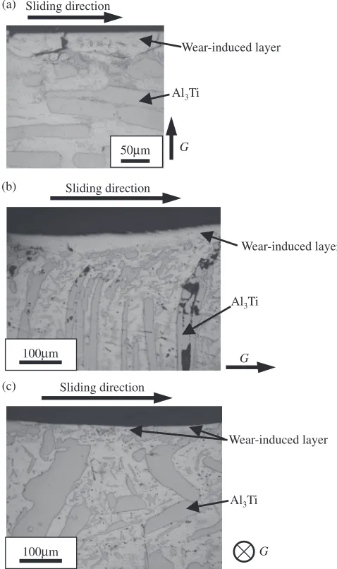
Figures 4(a)4(c) show the cross-sectional microstructures of the AlAl3Ti FGMs sample worn in the WA, WB and
WC directions, respectively. The wear-induced layers were observed near the worn surface in all the samples. Figures 5(a)5(c) are SEM micrographs showing the micro-structures below the wear-induced layer of the AlAl3Ti
FGMs sample worn in the WA, WB and WC directions,
respectively. Although the wear-induced layers are not observed in the photographs of the AlAl3Ti FGMs sample
worn in the WA and WC directions, this is because that these layers were delaminated during the electropolishing. Fine, fragmented Al3Ti particles and coarse Al3Ti platelet particles
were locally dispersed just below the wear-induced layer in the worn samples for the WA and WC directions (Figs. 5(a) and 5(c)). In addition, the coarse Al3Ti platelet particles in the
sample worn in WB direction were fractured in the sliding direction (Fig. 5(b)). The size of these fractured Al3Ti platelet
particles near the wear-induced layer was large compared with those in the samples worn in the WA and WC directions. It can be expected that the wear tests in the WA and WC directions would induce larger local shear strain than would the test in the WB direction.
The 3D distributions of the Al3Ti particles and the
wear-induced layer near the worn surface are presented in Fig. 6. In the samples worn in the WA and WC directions, very
fine fragmented Al3Ti particles were present just below the
wear-induced layer, and the unfragmented coarse Al3Ti
platelet particles remained below the region containing the
70µm 70µm
111
101 001 Al
Al3Ti Al Al3Ti
001 100 110
G
(a)
(b)
G
Al3Ti
Fig. 3 (a) IPF map [left] and phase map [right] and (b)ð001ÞAl3Ti pole figure of the cross-sectional microstructure near the outer surface of the AlAl3Ti FGMs ring before the wear test. Lattice directions of the coarse Al3Ti platelet particles are shown in the IPF map in (a).
Sliding direction
Wear-induced layer
Al3Ti
G
100µm
Wear-induced layer
Al3Ti
G
Sliding direction
Wear-induced layer
Al3Ti
G
Sliding direction
50µm
100µm
(c) (b) (a)
[image:3.595.48.281.59.367.2] [image:3.595.306.545.73.476.2]fragmented Al3Ti particles. In contrast, in the WB sample the
coarse Al3Ti platelet particles were fractured and tilted in the
sliding direction over the whole region in the 3D photograph. Because the fragmentation of the coarse Al3Ti platelet
particles in the WA and WC samples occurred below the wear-induced layer only, the wear tests for the WA and WC directions produced local shear strain on the worn surface. In addition, the wear-induced layer formed in the WA and WC samples continuously covered the worn surface, whereas the WB sample had a discontinuous wear-induced layer. Therefore, the formation of the wear-induced layer in the WA and WC directions was easier than in the WB direction.
To investigate the shear deformation behavior near the worn surface during wear, crystal orientation analysis was performed by using EBSD. Figure 7 shows the IPF and phase maps of the crystal orientation distributions for the worn surface. The arrows in these IPF maps indicate the deformation twins in the Al3Ti particles. The grains of the ¡-Al matrix just below the wear-induced layer were refined by the severe shear deformation caused by the wear. Deformation twins were also observed in the Al3Ti particles near the worn
surface for all the samples. It has been previously reported
that Al3Ti is plastically deformed by deformation twinning,
and the Al3Ti deformation twin was formed on theð112ÞAl3Ti
plane.15,16)The twin boundaries shown in Fig. 7 are parallel to the ð112ÞAl3Ti trace. The deformation twins observed in the present study were formed by a large shear deformation caused by the wear. The plastic deformation region, indicated by the distribution of the fragmented Al3Ti particles and
the refined or shear-deformed ¡-Al grains, showed that the samples worn in the WA and WC directions exhibited localized shear deformation, whereas widespread shear deformation occurred in WB sample. This local shear deformation of the worn surface enhanced the formation of the wear-induced layer. Therefore, the wear-induced layer in the AlAl3Ti FGMs ring is easily formed in the WA and WC
samples rather than the WB sample.
Figure 8 shows a ð001ÞAl3Ti pole figure and a schematic illustration of the distribution of Al3Ti particles near the worn
surface. In the sample worn in the WA direction,½001Al3Ti was almost parallel to the centrifugal direction (RD), which meant the coarse Al3Ti particles in the WA sample were
fragmented but did not rotate during wear. In Fig. 8(b), ½001Al3Ti changed from the transverse direction (TD) to the
RD during the wear test in the WB direction. This is in good agreement with the Al3Ti particle distribution in the 3D
photograph in Fig. 6(b). Because the Al3Ti platelet particles Al3Ti
Sliding direction Sliding direction
(c) (b) (a)
50µm
Sliding direction
50µm
Al3Ti
G
G
50µm
Al3Ti
G
Fig. 5 SEM backscatter electron compositional images showing the microstructures below the wear-induced layer of the AlAl3Ti FGM samples for the (a) WA, (b) WB and (c) WC directions.
Wear-induced layer
Al3Ti G
Wear-induced layer
Al3Ti
G
Wear-induced layer
Al3Ti
G
(a)(b)
(c)
[image:4.595.77.261.66.464.2] [image:4.595.334.518.72.426.2]were tilted toward the sliding direction by the simple shear deformation caused by the wear,½001Al3Timoved toward the RD. However, in the sample worn in the WC direction, ½001Al3Ti was concentrated in the ND. Because the Al3Ti
platelet particles in the WC sample initially had½001Al3Tiin the ND, the Al3Ti particles were fragmented and ½001Al3Ti
also did not move, as in the WA sample. These results show that the Al3Ti particles fragmented during the wear tests in
the WA and WC directions but did not rotate, whereas the particles fragmented and rotated during the wear test in the WB direction. Thus, the fragmentation of the Al3Ti particles
was similar for wear tests in the WA and WC directions.
3.3 Anisotropy of the wear resistance
Figure 9 shows the relationship between the weight loss caused by the wear tests and the sliding direction. The Al Al3Ti FGMs ring exhibited anisotropic wear resistance; the
weight loss for the wear tests in the WA and WC directions were smaller than that for the WB direction. Thus, the wear resistance in the WA and WC directions was higher than in
the WB direction. Although the wear resistance in the WC direction was the highest, the difference between WA and WC was smaller than that between WA and WB. This indicates that the wear behaviors for WA and WC were similar. The anisotropic wear resistance is consistent with previously reported results.6,8)
4. Discussion
4.1 Critical shear strain required to form the wear-induced layer
The wear-induced layer was observed in all the samples after the wear test. The amount of shear strain required to form the wear-induced layer was calculated to investigate its anisotropy.
Sato et al. proposed the method used for evaluating the amount of shear strain induced by wear.3) Figure 10 is a
schematic illustration of the simple shear deformation of a spherical grain. The circle (solid line) and the ellipse (broken line) represent an undeformed grain and a sheared grain,
111
101 001
Al
Al3Ti Al
50µm 50µm 50µm 50µm
50µm 50µm
(a) (b)
G
WB
WA WC
Al3Ti (c)
Al3Ti
Sliding Direction Sliding Direction Sliding Direction Sliding Direction
Sliding Direction Sliding Direction
G G
G
001 100
110
Plastic Deformation
Re
gion
Plastic Deformation
Re
gion
Plastic Deformation Re
gion
[image:5.595.84.511.73.493.2]respectively. When a grain with grain size D undergoes simple shear deformation during wear and its shape changes from a sphere to an ellipse with a thickness t, the nominal shear strain,¤nominal, can be written as
¤nominal¼ Dt 2
1
( )1
2
Dt ðDtÞ: ð1Þ
Onaka proposed that the large strain induced by severe plastic deformation could describe by the Hencky strain,
because it is logarithmic with a tensor component.17,18)Using
the Hencky strain and eq. (1), the equivalent Hencky strain,
¤hencky, for the simple shear deformation in Fig. 10 can be
written as5)
¤hencky 2 ln¤nominalffiffiffi
3
p ð¤nominal1Þ: ð2Þ
Equations (1) and (2) show that the critical shear strain required to form the wear-induced layer can be calculated by measuring the thickness of the shear-deformed grain just below the wear-induced layer.
The critical shear strains required to form the wear-induced layer for each sliding direction are shown in Table 1. The initial grain size of the ¡-Al matrix in the AlAl3Ti FGMs
ring wasD=110 µm. The critical equivalent Hencky strain required to form the wear-induced layer is about 5. The critical nominal shear strain for AlAl3Ti FGMs ring reported
in the previous studies3,5) is 90 and this corresponds to
¤hencky 5:2. Because of this, the critical shear strain
required to form the wear-induced layer obtained in the present study is close to the reported strain in those studies. Furthermore, the critical shear strain required to form the wear-induced layer did not depend on the sliding direction.
In previous studies, the microstructural evolution of commercial pure Al during accumulative roll bonding (ARB) has been investigated.19,20) The grains of pure Al
were refined as the number of ARB cycles increased. In addition, Pirgazi et al. reported that the fraction of high angle grain boundaries in pure Al that had undergone ARB
x
D D
t
Wear y
50µm
[image:6.595.47.290.66.415.2]t
Fig. 10 Schematic illustrations of the simple shear deformation of a spherical grain and the microstructure [top], and of the method of measuring the thickness of the shear deformed grain [bottom].
0.05 0.15
0.10 0.20 0.25
0
W
eight Loss,
W / g
WA WB WC
G
WB WC
Al3Ti WA
Fig. 9 Weight loss after the wear tests for the WA, WB and WC sliding directions.
TD
RD TD
RD
TD
RD Sliding Direction
Sliding Direction
Sliding Direction (a)
(b)
(c)
Al3Ti
Al3Ti
Al3Ti
G
G
G
ND
ND ND
Fig. 8 ð001ÞAl3Tipolefigures [left] and schematic illustrations [right] of the
[image:6.595.321.531.71.258.2]Al3Ti particle distributions near the worn surface for the (a) WA, (b) WB and (c) WC sliding directions.
Table 1 Critical shear strain required to form the wear-induced layer.
Sliding direction
Average thickness of grain,
t
Critical shear strain
Nominal shear strain,
¤nominal
Equivalent Hencky strain,
¤hencky
WA 1.39 79.1 5.0
WB 1.49 73.8 5.0
[image:6.595.303.548.327.415.2] [image:6.595.62.281.472.637.2]increased to more than 72% after 6 cycles, and that polycrystalline Al with ultrafine grains was obtained.20)This
number of ARB cycles corresponds to an equivalent Hencky strain of 4.8, which is similar to the critical strain required to form the wear-induced layer. Therefore, we propose that the equivalent Hencky strain of about 5 is the strain required to form ultrafine grains.
4.2 Anisotropy of the wear behavior
The microstructure near the wear-induced layer and the wear resistance in the AlAl3Ti FGMs ring depended on the
sliding direction of the wear tests. The anisotropic behavior arose from the fracture behavior of the coarse Al3Ti platelet
particles, which depended on the sliding direction. Figure 11 shows a schematic illustration of the shear-stress directions, indicated by arrows, of a coarse Al3Ti particle for each
sliding direction. For the WA direction, the shear stress was introduced in the plane of the Al3Ti platelet particles, and the
contact area of the coarse Al3Ti platelet particles with the
worn surface was the largest. However, for the WC direction, the shear stress was introduced on the edge plane of the particle, which would make it difficult to fracture the particle. Because of this, the coarse Al3Ti platelet particles were only
fragmented near the worn surface and the fine fragmented particles were distributed there. As a result, the shear deformation during the wear tests in the WA and WC directions was local and the shear strain was high close to the worn surface only. However, the wear test in the WB direction caused the shear deformation of the coarse Al3Ti
platelet particles (Fig. 11), and the particles were easily broken. Consequently, the strain was introduced over a wide area. Therefore, the wear resistance of the AlAl3Ti FGMs
ring was higher for wear tests in the WA and WC directions and the wear-induced layer formed easily in these wear directions. Finally, the anisotropy of the wear behavior also arose from the local shear strain at the worn surface because of the distribution of the coarse Al3Ti platelet particles.
5. Conclusions
Microstructural evolution near the worn surface of the Al Al3Ti FGMs ring was investigated in three dimensions by the
serial sectioning and crystal orientation analysis of the Al3Ti
particles using EBSD. The main conclusions about the anisotropy of the wear resistance and the formation behavior
of the wear-induced layer in the AlAl3Ti FGMs ring are
summarized below.
(1) When the AlAl3Ti FGMs ring was worn along the
longitudinal direction of the ring on its outer surface or its thickness plane (WA and WC direction), the coarse Al3Ti platelet particles were severely fragmented near
the worn surface only. However, when the wear test was performed along the radial direction of the ring on its thickness plane (WB direction), the coarse Al3Ti
platelet particles were broken into relatively large fragments over a wide region.
(2) The wear resistance and the formation of the wear-induced layer depended on the sliding direction. The anisotropy was explained by the local shear deforma-tion caused by the Al3Ti particle distribution.
(3) The critical equivalent Hencky strain required to form the wear-induced layer was ³5, and it did not depend on the sliding direction. The equivalent Hencky strain of about 5 is the strain required to form ultrafine grains.
Acknowledgments
This research was supported by “Grant-in-Aid for Young Scientists B (23760664)”, “Tokai Region Nanotechnology Manufacturing Cluster” from the Ministry of Education, Culture, Sports, Science and Technology of Japan, and“The Light Metal Educational Foundation Inc. of Japan”. These
financial supports were gratefully acknowledged.
REFERENCES
1) J. H. Dautzenberg and J. H. Zaat:Wear23(1973) 919.
2) P. Heilmann, W. A. T. Clark and D. A. Rigney:Acta Metall.31(1983) 12931305.
3) H. Sato, T. Murase, T. Fujii, S. Onaka, Y. Watanabe and M. Kato:Acta Mater.56(2008) 45494558.
4) A. Emge, S. Karthikeyan and D. A. Rigney:Wear267(2009) 562567. 5) H. Sato, E. Miura-Fujiwara and Y. Watanabe:Materia Japan50(2011)
331338 (Japanese).
6) Y. Watanabe, N. Yamanaka and Y. Fukui:Metall. Mater. Trans. A30 (1999) 32533261.
7) Y. Watanabe, K. Yokoyama and H. Hosoda:Mater. Sci. Forum396 402(2002) 14671472.
8) Y. Watanabe, H. Sato and Y. Fukui:J. Solid Mech. Mater. Eng.2(2008) 842853.
9) K. Yamashita, C. Watanabe, S. Kumai, M. Kato, A. Sato and Y. Watanabe: Mater. Trans. JIM41(2000) 13221328.
10) Y. Watanabe, H. Eryu and K. Matsuura:Acta Mater.49(2001) 775 783.
11) P. D. Sequeira, Y. Watanabe and Y. Fukui:Scr. Mater.53(2005) 687 692.
12) S. Zaefferer, S. I. Wright and D. Raabe:Metall. Mater. Trans. A39 (2008) 374389.
13) Y. Adachi: Bull. Iron Steel Inst. Japan13(2008) 676680.
14) S. Morito, Y. Adachi and T. Ohba:Mater. Trans.50(2009) 19191923. 15) M. Yamaguchi, Y. Umakoshi and T. Yamane:Philos. Mag. A55(1987)
301315.
16) M. Yamaguchi, F. Nakamura and Y. Shirai:J. JILM38(1988) 228237 (Japanese).
17) S. Onaka:J. Japan. Inst. Metals74(2010) 165170 (Japanese). 18) S. Onaka:Philos. Mag. Lett.90(2010) 633639.
19) Y. Saito, H. Utsunomiya, N. Tsuji and T. Sakai:Acta Mater.47(1999) 579583.
20) H. Pirgazi, A. Akbarzadeh, R. Petrov and L. Kestens:Mater. Sci. Eng. A497(2008) 132138.
WB
WA
[image:7.595.105.233.68.204.2]Al3Ti platelet particles


![Fig. 7IPF maps [left] and phase maps [right] showing cross-sectional microstructures near the worn surfaces of the (a) WA, (b) WB and(c) WC samples](https://thumb-us.123doks.com/thumbv2/123dok_us/320781.530797/5.595.84.511.73.493/phase-right-showing-cross-sectional-microstructures-surfaces-samples.webp)


